EP2664868A2 - Dispositif de pompe à chaleur et évaporateur pour un dispositif de pompe à chaleur - Google Patents
Dispositif de pompe à chaleur et évaporateur pour un dispositif de pompe à chaleur Download PDFInfo
- Publication number
- EP2664868A2 EP2664868A2 EP13002529.9A EP13002529A EP2664868A2 EP 2664868 A2 EP2664868 A2 EP 2664868A2 EP 13002529 A EP13002529 A EP 13002529A EP 2664868 A2 EP2664868 A2 EP 2664868A2
- Authority
- EP
- European Patent Office
- Prior art keywords
- evaporator
- heat pump
- refrigerant
- heat
- fins
- Prior art date
- Legal status (The legal status is an assumption and is not a legal conclusion. Google has not performed a legal analysis and makes no representation as to the accuracy of the status listed.)
- Granted
Links
Images


Classifications
-
- F—MECHANICAL ENGINEERING; LIGHTING; HEATING; WEAPONS; BLASTING
- F28—HEAT EXCHANGE IN GENERAL
- F28F—DETAILS OF HEAT-EXCHANGE AND HEAT-TRANSFER APPARATUS, OF GENERAL APPLICATION
- F28F1/00—Tubular elements; Assemblies of tubular elements
- F28F1/10—Tubular elements and assemblies thereof with means for increasing heat-transfer area, e.g. with fins, with projections, with recesses
- F28F1/12—Tubular elements and assemblies thereof with means for increasing heat-transfer area, e.g. with fins, with projections, with recesses the means being only outside the tubular element
- F28F1/24—Tubular elements and assemblies thereof with means for increasing heat-transfer area, e.g. with fins, with projections, with recesses the means being only outside the tubular element and extending transversely
- F28F1/32—Tubular elements and assemblies thereof with means for increasing heat-transfer area, e.g. with fins, with projections, with recesses the means being only outside the tubular element and extending transversely the means having portions engaging further tubular elements
-
- F—MECHANICAL ENGINEERING; LIGHTING; HEATING; WEAPONS; BLASTING
- F25—REFRIGERATION OR COOLING; COMBINED HEATING AND REFRIGERATION SYSTEMS; HEAT PUMP SYSTEMS; MANUFACTURE OR STORAGE OF ICE; LIQUEFACTION SOLIDIFICATION OF GASES
- F25B—REFRIGERATION MACHINES, PLANTS OR SYSTEMS; COMBINED HEATING AND REFRIGERATION SYSTEMS; HEAT PUMP SYSTEMS
- F25B30/00—Heat pumps
- F25B30/02—Heat pumps of the compression type
-
- F—MECHANICAL ENGINEERING; LIGHTING; HEATING; WEAPONS; BLASTING
- F25—REFRIGERATION OR COOLING; COMBINED HEATING AND REFRIGERATION SYSTEMS; HEAT PUMP SYSTEMS; MANUFACTURE OR STORAGE OF ICE; LIQUEFACTION SOLIDIFICATION OF GASES
- F25B—REFRIGERATION MACHINES, PLANTS OR SYSTEMS; COMBINED HEATING AND REFRIGERATION SYSTEMS; HEAT PUMP SYSTEMS
- F25B39/00—Evaporators; Condensers
- F25B39/02—Evaporators
-
- F—MECHANICAL ENGINEERING; LIGHTING; HEATING; WEAPONS; BLASTING
- F25—REFRIGERATION OR COOLING; COMBINED HEATING AND REFRIGERATION SYSTEMS; HEAT PUMP SYSTEMS; MANUFACTURE OR STORAGE OF ICE; LIQUEFACTION SOLIDIFICATION OF GASES
- F25B—REFRIGERATION MACHINES, PLANTS OR SYSTEMS; COMBINED HEATING AND REFRIGERATION SYSTEMS; HEAT PUMP SYSTEMS
- F25B47/00—Arrangements for preventing or removing deposits or corrosion, not provided for in another subclass
- F25B47/02—Defrosting cycles
-
- F—MECHANICAL ENGINEERING; LIGHTING; HEATING; WEAPONS; BLASTING
- F28—HEAT EXCHANGE IN GENERAL
- F28D—HEAT-EXCHANGE APPARATUS, NOT PROVIDED FOR IN ANOTHER SUBCLASS, IN WHICH THE HEAT-EXCHANGE MEDIA DO NOT COME INTO DIRECT CONTACT
- F28D1/00—Heat-exchange apparatus having stationary conduit assemblies for one heat-exchange medium only, the media being in contact with different sides of the conduit wall, in which the other heat-exchange medium is a large body of fluid, e.g. domestic or motor car radiators
- F28D1/02—Heat-exchange apparatus having stationary conduit assemblies for one heat-exchange medium only, the media being in contact with different sides of the conduit wall, in which the other heat-exchange medium is a large body of fluid, e.g. domestic or motor car radiators with heat-exchange conduits immersed in the body of fluid
- F28D1/04—Heat-exchange apparatus having stationary conduit assemblies for one heat-exchange medium only, the media being in contact with different sides of the conduit wall, in which the other heat-exchange medium is a large body of fluid, e.g. domestic or motor car radiators with heat-exchange conduits immersed in the body of fluid with tubular conduits
- F28D1/047—Heat-exchange apparatus having stationary conduit assemblies for one heat-exchange medium only, the media being in contact with different sides of the conduit wall, in which the other heat-exchange medium is a large body of fluid, e.g. domestic or motor car radiators with heat-exchange conduits immersed in the body of fluid with tubular conduits the conduits being bent, e.g. in a serpentine or zig-zag
- F28D1/0477—Heat-exchange apparatus having stationary conduit assemblies for one heat-exchange medium only, the media being in contact with different sides of the conduit wall, in which the other heat-exchange medium is a large body of fluid, e.g. domestic or motor car radiators with heat-exchange conduits immersed in the body of fluid with tubular conduits the conduits being bent, e.g. in a serpentine or zig-zag the conduits being bent in a serpentine or zig-zag
-
- F—MECHANICAL ENGINEERING; LIGHTING; HEATING; WEAPONS; BLASTING
- F28—HEAT EXCHANGE IN GENERAL
- F28F—DETAILS OF HEAT-EXCHANGE AND HEAT-TRANSFER APPARATUS, OF GENERAL APPLICATION
- F28F17/00—Removing ice or water from heat-exchange apparatus
- F28F17/005—Means for draining condensates from heat exchangers, e.g. from evaporators
-
- F—MECHANICAL ENGINEERING; LIGHTING; HEATING; WEAPONS; BLASTING
- F25—REFRIGERATION OR COOLING; COMBINED HEATING AND REFRIGERATION SYSTEMS; HEAT PUMP SYSTEMS; MANUFACTURE OR STORAGE OF ICE; LIQUEFACTION SOLIDIFICATION OF GASES
- F25B—REFRIGERATION MACHINES, PLANTS OR SYSTEMS; COMBINED HEATING AND REFRIGERATION SYSTEMS; HEAT PUMP SYSTEMS
- F25B2400/00—Component parts or details not otherwise provided for in this subclass
- F25B2400/13—Economisers
Definitions
- the present invention relates to a heat pump device and an evaporator for a heat pump device.
- Heat pumps are used, for example, for heating heating water.
- the heat generated by the heat pump is transferred to a heating medium, for example by means of a condenser.
- the heat pump generates heat by condensation of refrigerant under high pressure and thus at high temperature, while the heat generated thereby is delivered to a heat transfer medium (heating water), for example in a condenser.
- the condenser the refrigerant is liquefied and then expanded in a throttle body, for example in an expansion valve. Upon absorption of ambient heat, it then evaporates in the evaporator.
- the gaseous refrigerant is then fed to a compressor and compressed in the compressor.
- the compressed refrigerant is then supplied to the condenser, in which the refrigerant is in turn liquefied and thereby emits heat to a heat transfer medium.
- the present invention relates to an air-refrigerant evaporator unit having at least a first pipe for refrigerant having a first port as a refrigerant inlet and a second port as Kälternittelablauf, wherein the tube absorbs heat and releases to the refrigerant, a plurality of fins and a second tube as Replacement length with a third and a fourth connection, which absorbs heat from the refrigerant and can release it again.
- the evaporator unit may optionally have end blades which are longer than the other blades.
- the end lamellae or the extended lamellar plates serve for the mechanical reception of an immersion length integrated in the evaporator.
- the evaporator unit may optionally have a defrosting tray of sheet metal, plastic or EPS foamed.
- the evaporator unit may have the Ableylange and / or the Abtauwanne in the lower region.
- the evaporator unit may have a pipe guide in its lower third.
- the invention also relates to an air-refrigerant evaporator having a first conduit for refrigerant for absorbing heat by evaporation of the refrigerant and a second conduit with refrigerant for emitting heat by subcooling the liquid refrigerant.
- the evaporator may include a plurality of fins which are thermally coupled only to the first conduit to facilitate vaporization of the refrigerant.
- the invention also relates to a heat pump device with a fin tube heat exchanger as evaporator and subcooler coil for heating a condensate tray for the evaporator.
- the subcooler coil is provided in or on the evaporator and serves to heat the condensate tray and / or condensate located in the condensate tray.
- the heat pump device includes an evaporator mechanically connected to the subcooler coil.
- the evaporator may have a plurality of fins, wherein the subcooler coil is connected to some of the fins.
- the subcooler coil is only connected to some of the fins but not to all fins.
- the subcooler coil and advantageously an evaporator injection line, is connected at one location to one of the fins to minimize vibration transfer from the refrigerant from the refrigerant circuit to the tubes of the subcooler coil.
- the present invention is based on the finding that, for example, in an air-water heat pump apparatus, an evaporator with a finned tube heat exchanger is used.
- an evaporator with a finned tube heat exchanger is used.
- the evaporator is constructed from a plurality of rows of tubes, for example in the direction of flow of the air one behind the other, the evaporator is typically provided with end lamellae for mechanical stabilization of the tubes. These end blades are used in particular to provide attachment points for the pipes.
- a condensate tray may be provided which serves to catch the condensate forming during operation or during the defrosting of the heat pump device.
- the invention serves to provide an improved way of heating the condensate tray.
- heat from the refrigeration circuit can be used.
- an evaporator is provided, which is another cooling coil to heat the Kons nsatwanne and / or the condensate therein.
- a further cooling coil consisting of at least one bent tube is provided.
- the Endlamellen be designed so that they also serve to hold the additional cooling coil.
- Fig. 1 shows a schematic representation of a heat pump device according to a first embodiment.
- the heat pump apparatus comprises a compressor 10, a condenser 20, an evaporator 30, a first electronic expansion valve 40, optionally a filter drier 70, optionally a further electronic expansion valve 80, optionally an economizer 60, an evaporator 30, a four- / two-way valve 50 and a Swap 90 on.
- the compressor 10 serves to compress gaseous coolant.
- the compressor may have a steam injection.
- the condenser 20 serves to liquefy the refrigerant and to transfer the heat released thereby to a heating medium such as heating water.
- the heat pump device further optionally has a valve 3, a sight glass 2 and injection capillaries 4.
- An evaporator unit consists of the evaporator 30 and advantageously has a fan or fan 31, which blows air through the evaporator 30.
- the evaporator unit or the evaporator 30 may include a defrosting trough 100, which may be heated by, for example, the defrosting tray 90.
- the heat pump device can be operated in a heating mode H or in a defrosting mode A.
- the direction of the refrigerant within the refrigerant circuit is indicated by the arrows H in the heating mode and by the arrows A in the defrosting mode.
- the heat pump according to the invention is for example an air-water heat pump.
- the defrosting length 90 which is used to heat the defrosting trough 100 of the evaporator, is part of the refrigeration cycle.
- liquid refrigerant flows in the Ab (2004).
- a heating of the defrosting trough of the evaporator is particularly useful at outside temperatures of below 0 ° C, because accumulating condensate can freeze.
- the refrigerant used may be R407C, R410A, R290, R744 or R134a.
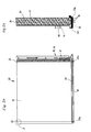
- Fig. 2a, 2b , and 2c show various views of an evaporator according to a second embodiment.
- the evaporator according to the second embodiment may be used in the heat pump apparatus according to the first embodiment.
- the evaporator 30 has a first line 36 with an inlet connection 34 and an outlet connection 35.
- the conduit 36 extends in a plurality of turns within the evaporator 30.
- the conduit 36 may include a venturi manifold 37.
- a plurality of fins 32 are typically provided.
- the lamellae 32 preferably form a lamella packet which ends on the right and left, each with an end plate 33.
- the end plates 33 have extensions 33a at their first end.
- a Ableylange 90 with an inlet 91 and a drain 92 is provided in the lower part of the distributor.
- This Ableylange 90, the Ableylange 90 according to the first embodiment of Fig. 1 correspond.
- liquid refrigerant flows in the Ableylange 90.
- the Ableylange 90 essentially represents a second line, which can be maintained for example by the extended portions 33 a of the lamella plates.
- the second line 90 may be provided, for example, in the lower region of the evaporator.
- the evaporator 30 is provided in cross section and a defrosting trough 100.
- Fig. 2d shows the fins 32 of the evaporator 30 in an enlarged detail.
- the fins 32 are so close to each other that they are not shown.
- the line 36 preferably leads horizontally from a first end plate 33 through the slats 32 to the opposite end plate 33 and preferably back again.
- the Ableylange 90 serves to absorb heat from the liquid refrigerant and preferably to the defrosting trough 100 deliver.
- the piping is the second conduit, i. the line of Ab (2004)lange, provided in the lower part of the evaporator.
- the Ableylange 90 may be configured, for example, as a subcooler coil and may for example be made of the same material or tubes, as the tubes of the first line, i. the pipes that carry the refrigerant through the evaporator.
- the subcooler coil 90 may be structurally connected to at least one or two end fins 33, but without connection to the other fins 32 of the evaporator.
- the connecting pipes 91, 92 of the subcooler coil and the replacement pipe and the injection pipe 43 of the evaporator are preferably laid so that they are connected to one of the end plates, so that a structural unit is formed.
- the connection of the pipes is provided locally to the refrigerant circuit, so that any vibrations occurring in the refrigerant circuit are absorbed by the entire evaporator unit or by the evaporator.
- the removal trough is attached to a housing part, such as a strut, a support or a sheet metal part, and the evaporator unit is placed on the defrosting trough.
- the defrost pan is clamped to the evaporator unit, screwed, glued or otherwise advantageously removably connected to the evaporator unit.
- the evaporator unit connected to the defrosting pan is advantageously used completely in a chassis of a heat pump during assembly.
Landscapes
- Engineering & Computer Science (AREA)
- Physics & Mathematics (AREA)
- Thermal Sciences (AREA)
- Mechanical Engineering (AREA)
- General Engineering & Computer Science (AREA)
- Geometry (AREA)
- Defrosting Systems (AREA)
- Heat-Pump Type And Storage Water Heaters (AREA)
Applications Claiming Priority (1)
| Application Number | Priority Date | Filing Date | Title |
|---|---|---|---|
| DE202012004795U DE202012004795U1 (de) | 2012-05-15 | 2012-05-15 | Wärmepumpenvorrichtung und Verdampfer für eine Wärmepumpenvorrichtung |
Publications (3)
| Publication Number | Publication Date |
|---|---|
| EP2664868A2 true EP2664868A2 (fr) | 2013-11-20 |
| EP2664868A3 EP2664868A3 (fr) | 2016-08-03 |
| EP2664868B1 EP2664868B1 (fr) | 2021-03-17 |
Family
ID=48444020
Family Applications (1)
| Application Number | Title | Priority Date | Filing Date |
|---|---|---|---|
| EP13002529.9A Active EP2664868B1 (fr) | 2012-05-15 | 2013-05-14 | Dispositif de pompe à chaleur et évaporateur pour un dispositif de pompe à chaleur |
Country Status (2)
| Country | Link |
|---|---|
| EP (1) | EP2664868B1 (fr) |
| DE (1) | DE202012004795U1 (fr) |
Cited By (3)
| Publication number | Priority date | Publication date | Assignee | Title |
|---|---|---|---|---|
| EP3034674A1 (fr) * | 2014-12-17 | 2016-06-22 | Miele & Cie. KG | Dispositif et procede de preparation de puissance de chauffe pour un appareil de traitement de linge et appareil de traitement de linge |
| CN104296286B (zh) * | 2014-10-17 | 2017-05-03 | 江苏辛普森新能源有限公司 | 一种带蓄冰蓄热功能的热源塔制冷供热节能设备 |
| CN108954980A (zh) * | 2018-06-21 | 2018-12-07 | 深圳市派沃新能源科技股份有限公司 | 一种翅片式蒸发器、热泵系统及控制方法 |
Families Citing this family (4)
| Publication number | Priority date | Publication date | Assignee | Title |
|---|---|---|---|---|
| CN106288482B (zh) * | 2015-05-19 | 2019-03-12 | Tcl空调器(中山)有限公司 | 空调器 |
| DE102023136086A1 (de) | 2023-12-20 | 2025-06-26 | Stiebel Eltron Gmbh & Co. Kg | Kältekreis einer Wärmepumpe und Wärmepumpe |
| DE102023136084A1 (de) * | 2023-12-20 | 2025-06-26 | Stiebel Eltron Gmbh & Co. Kg | Verfahren zum Betrieb einer Wärmepumpe mit einem Dampfkompressionssystem |
| DE102023136088A1 (de) | 2023-12-20 | 2025-06-26 | Stiebel Eltron Gmbh & Co. Kg | Kältekreis einer Wärmepumpe und Wärmepumpen |
Family Cites Families (7)
| Publication number | Priority date | Publication date | Assignee | Title |
|---|---|---|---|---|
| JPS5380042A (en) * | 1976-12-24 | 1978-07-15 | Hitachi Ltd | Evaporator for refrigerator |
| DE4321161C2 (de) * | 1993-06-25 | 2001-02-22 | Stiebel Eltron Gmbh & Co Kg | Wärmepumpenanlage |
| DE19644488A1 (de) * | 1996-10-25 | 1998-04-30 | Friedhelm Meyer | Verfahren und Vorrichtung zum Abtauen eines Kühlers einer Kälteanlage |
| SK4118U (sk) * | 2004-03-15 | 2005-05-05 | Stanislav Mach | Tepelné čerpadlo |
| DE102005018125A1 (de) * | 2005-04-20 | 2006-10-26 | Bernhard Wenzel | Kältemittelkreislauf für eine Wärmepumpe |
| CN101187515A (zh) * | 2006-11-17 | 2008-05-28 | 陈则韶 | 增加有防霜换热管的风源热泵 |
| JP2009127926A (ja) * | 2007-11-22 | 2009-06-11 | Panasonic Corp | 除霜ヒータ付き冷却器および物品貯蔵装置 |
-
2012
- 2012-05-15 DE DE202012004795U patent/DE202012004795U1/de not_active Expired - Lifetime
-
2013
- 2013-05-14 EP EP13002529.9A patent/EP2664868B1/fr active Active
Non-Patent Citations (1)
| Title |
|---|
| None |
Cited By (3)
| Publication number | Priority date | Publication date | Assignee | Title |
|---|---|---|---|---|
| CN104296286B (zh) * | 2014-10-17 | 2017-05-03 | 江苏辛普森新能源有限公司 | 一种带蓄冰蓄热功能的热源塔制冷供热节能设备 |
| EP3034674A1 (fr) * | 2014-12-17 | 2016-06-22 | Miele & Cie. KG | Dispositif et procede de preparation de puissance de chauffe pour un appareil de traitement de linge et appareil de traitement de linge |
| CN108954980A (zh) * | 2018-06-21 | 2018-12-07 | 深圳市派沃新能源科技股份有限公司 | 一种翅片式蒸发器、热泵系统及控制方法 |
Also Published As
| Publication number | Publication date |
|---|---|
| DE202012004795U1 (de) | 2013-08-20 |
| EP2664868A3 (fr) | 2016-08-03 |
| EP2664868B1 (fr) | 2021-03-17 |
Similar Documents
| Publication | Publication Date | Title |
|---|---|---|
| EP2664868A2 (fr) | Dispositif de pompe à chaleur et évaporateur pour un dispositif de pompe à chaleur | |
| DE112017003668B4 (de) | Thermomanagementsystem für ein Fahrzeug | |
| DE10355936A1 (de) | Wärmetauscher | |
| DE102012100722A1 (de) | Interner Wärmetauscher | |
| EP2638337B1 (fr) | Évaporateur | |
| DE102023202885A1 (de) | Vorrichtung zum Temperieren eines Raums, Gas-Flüssigkeits-Wärmetauscher und Lastkraftwagen | |
| DE112018000718T5 (de) | Kältemittelrohr und Kühlkreislaufgerät | |
| DE102020202313A1 (de) | Wärmeübertrager | |
| DE102013223697A1 (de) | Kühlmodul für ein Fahrzeug | |
| WO2004055450A2 (fr) | Circuit de refrigerant et installation frigorifique | |
| EP2660542A2 (fr) | Appareil de réfrigération et/ou de congélation | |
| DE19802008C2 (de) | Gefrierverfahren und Wärmetauscher zur Kondensation | |
| DE102012110237B4 (de) | Druckluft-Kältetrockner | |
| DE102005061480B3 (de) | Wärmepumpenanlage | |
| EP2389545B1 (fr) | Appareil pour la climatisation avec refroidissement de l'air frais sans emploi d' une machine de refrigeration | |
| DE60118722T3 (de) | Die Verwendung einer Kältemittelrohrleitung für eine Fahrzeugklimaanlage | |
| DE102020205244B4 (de) | Verfahren zum Betreiben eines Kältemittelverdichters in einem Fahrzeug, Kältemittelverdichter und Fahrzeug | |
| DE102005027674A1 (de) | Klimaanlage für Fahrzeugverwendung | |
| DE69818696T2 (de) | Kondensator für wärmeaustauschsysteme | |
| DE102014216216A1 (de) | Kreisförmiger Wärmetauscher mit angeformtem Trockner und Kältekreislauf mit diesem Wärmetauscher | |
| DE102008024562B4 (de) | Wärmepumpenvorrichtung mit einem Lamellenrohrwärmeübertrager als Verdampfer | |
| DE1275896B (de) | Klimaanlage zur Kuehlung und Heizung von Kraftfahrzeugen | |
| EP2409103B1 (fr) | Unité d'échange de chaleur et installation thermotechnique | |
| DE112021006979T5 (de) | Kältekreislaufgerät | |
| DE102010034111A1 (de) | Kraftfahrzeug-Klimaanlage |
Legal Events
| Date | Code | Title | Description |
|---|---|---|---|
| PUAI | Public reference made under article 153(3) epc to a published international application that has entered the european phase |
Free format text: ORIGINAL CODE: 0009012 |
|
| AK | Designated contracting states |
Kind code of ref document: A2 Designated state(s): AL AT BE BG CH CY CZ DE DK EE ES FI FR GB GR HR HU IE IS IT LI LT LU LV MC MK MT NL NO PL PT RO RS SE SI SK SM TR |
|
| AX | Request for extension of the european patent |
Extension state: BA ME |
|
| PUAL | Search report despatched |
Free format text: ORIGINAL CODE: 0009013 |
|
| AK | Designated contracting states |
Kind code of ref document: A3 Designated state(s): AL AT BE BG CH CY CZ DE DK EE ES FI FR GB GR HR HU IE IS IT LI LT LU LV MC MK MT NL NO PL PT RO RS SE SI SK SM TR |
|
| AX | Request for extension of the european patent |
Extension state: BA ME |
|
| RIC1 | Information provided on ipc code assigned before grant |
Ipc: F25B 39/02 20060101ALI20160628BHEP Ipc: F25B 30/02 20060101ALI20160628BHEP Ipc: F28F 17/00 20060101ALI20160628BHEP Ipc: F28F 1/32 20060101ALI20160628BHEP Ipc: F25B 47/02 20060101ALI20160628BHEP Ipc: F25B 13/00 20060101AFI20160628BHEP Ipc: F28D 1/047 20060101ALI20160628BHEP |
|
| STAA | Information on the status of an ep patent application or granted ep patent |
Free format text: STATUS: REQUEST FOR EXAMINATION WAS MADE |
|
| 17P | Request for examination filed |
Effective date: 20170203 |
|
| RBV | Designated contracting states (corrected) |
Designated state(s): AL AT BE BG CH CY CZ DE DK EE ES FI FR GB GR HR HU IE IS IT LI LT LU LV MC MK MT NL NO PL PT RO RS SE SI SK SM TR |
|
| STAA | Information on the status of an ep patent application or granted ep patent |
Free format text: STATUS: EXAMINATION IS IN PROGRESS |
|
| 17Q | First examination report despatched |
Effective date: 20170818 |
|
| GRAP | Despatch of communication of intention to grant a patent |
Free format text: ORIGINAL CODE: EPIDOSNIGR1 |
|
| STAA | Information on the status of an ep patent application or granted ep patent |
Free format text: STATUS: GRANT OF PATENT IS INTENDED |
|
| INTG | Intention to grant announced |
Effective date: 20201014 |
|
| GRAS | Grant fee paid |
Free format text: ORIGINAL CODE: EPIDOSNIGR3 |
|
| GRAA | (expected) grant |
Free format text: ORIGINAL CODE: 0009210 |
|
| STAA | Information on the status of an ep patent application or granted ep patent |
Free format text: STATUS: THE PATENT HAS BEEN GRANTED |
|
| AK | Designated contracting states |
Kind code of ref document: B1 Designated state(s): AL AT BE BG CH CY CZ DE DK EE ES FI FR GB GR HR HU IE IS IT LI LT LU LV MC MK MT NL NO PL PT RO RS SE SI SK SM TR |
|
| REG | Reference to a national code |
Ref country code: GB Ref legal event code: FG4D Free format text: NOT ENGLISH |
|
| REG | Reference to a national code |
Ref country code: CH Ref legal event code: EP |
|
| REG | Reference to a national code |
Ref country code: DE Ref legal event code: R096 Ref document number: 502013015561 Country of ref document: DE |
|
| REG | Reference to a national code |
Ref country code: IE Ref legal event code: FG4D Free format text: LANGUAGE OF EP DOCUMENT: GERMAN |
|
| REG | Reference to a national code |
Ref country code: AT Ref legal event code: REF Ref document number: 1372613 Country of ref document: AT Kind code of ref document: T Effective date: 20210415 |
|
| REG | Reference to a national code |
Ref country code: SE Ref legal event code: TRGR |
|
| REG | Reference to a national code |
Ref country code: LT Ref legal event code: MG9D |
|
| PG25 | Lapsed in a contracting state [announced via postgrant information from national office to epo] |
Ref country code: FI Free format text: LAPSE BECAUSE OF FAILURE TO SUBMIT A TRANSLATION OF THE DESCRIPTION OR TO PAY THE FEE WITHIN THE PRESCRIBED TIME-LIMIT Effective date: 20210317 Ref country code: GR Free format text: LAPSE BECAUSE OF FAILURE TO SUBMIT A TRANSLATION OF THE DESCRIPTION OR TO PAY THE FEE WITHIN THE PRESCRIBED TIME-LIMIT Effective date: 20210618 Ref country code: HR Free format text: LAPSE BECAUSE OF FAILURE TO SUBMIT A TRANSLATION OF THE DESCRIPTION OR TO PAY THE FEE WITHIN THE PRESCRIBED TIME-LIMIT Effective date: 20210317 Ref country code: BG Free format text: LAPSE BECAUSE OF FAILURE TO SUBMIT A TRANSLATION OF THE DESCRIPTION OR TO PAY THE FEE WITHIN THE PRESCRIBED TIME-LIMIT Effective date: 20210617 Ref country code: NO Free format text: LAPSE BECAUSE OF FAILURE TO SUBMIT A TRANSLATION OF THE DESCRIPTION OR TO PAY THE FEE WITHIN THE PRESCRIBED TIME-LIMIT Effective date: 20210617 |
|
| REG | Reference to a national code |
Ref country code: NL Ref legal event code: MP Effective date: 20210317 |
|
| PG25 | Lapsed in a contracting state [announced via postgrant information from national office to epo] |
Ref country code: RS Free format text: LAPSE BECAUSE OF FAILURE TO SUBMIT A TRANSLATION OF THE DESCRIPTION OR TO PAY THE FEE WITHIN THE PRESCRIBED TIME-LIMIT Effective date: 20210317 Ref country code: LV Free format text: LAPSE BECAUSE OF FAILURE TO SUBMIT A TRANSLATION OF THE DESCRIPTION OR TO PAY THE FEE WITHIN THE PRESCRIBED TIME-LIMIT Effective date: 20210317 |
|
| PG25 | Lapsed in a contracting state [announced via postgrant information from national office to epo] |
Ref country code: NL Free format text: LAPSE BECAUSE OF FAILURE TO SUBMIT A TRANSLATION OF THE DESCRIPTION OR TO PAY THE FEE WITHIN THE PRESCRIBED TIME-LIMIT Effective date: 20210317 |
|
| PG25 | Lapsed in a contracting state [announced via postgrant information from national office to epo] |
Ref country code: SM Free format text: LAPSE BECAUSE OF FAILURE TO SUBMIT A TRANSLATION OF THE DESCRIPTION OR TO PAY THE FEE WITHIN THE PRESCRIBED TIME-LIMIT Effective date: 20210317 Ref country code: EE Free format text: LAPSE BECAUSE OF FAILURE TO SUBMIT A TRANSLATION OF THE DESCRIPTION OR TO PAY THE FEE WITHIN THE PRESCRIBED TIME-LIMIT Effective date: 20210317 Ref country code: CZ Free format text: LAPSE BECAUSE OF FAILURE TO SUBMIT A TRANSLATION OF THE DESCRIPTION OR TO PAY THE FEE WITHIN THE PRESCRIBED TIME-LIMIT Effective date: 20210317 Ref country code: LT Free format text: LAPSE BECAUSE OF FAILURE TO SUBMIT A TRANSLATION OF THE DESCRIPTION OR TO PAY THE FEE WITHIN THE PRESCRIBED TIME-LIMIT Effective date: 20210317 |
|
| PG25 | Lapsed in a contracting state [announced via postgrant information from national office to epo] |
Ref country code: RO Free format text: LAPSE BECAUSE OF FAILURE TO SUBMIT A TRANSLATION OF THE DESCRIPTION OR TO PAY THE FEE WITHIN THE PRESCRIBED TIME-LIMIT Effective date: 20210317 Ref country code: IS Free format text: LAPSE BECAUSE OF FAILURE TO SUBMIT A TRANSLATION OF THE DESCRIPTION OR TO PAY THE FEE WITHIN THE PRESCRIBED TIME-LIMIT Effective date: 20210717 Ref country code: PT Free format text: LAPSE BECAUSE OF FAILURE TO SUBMIT A TRANSLATION OF THE DESCRIPTION OR TO PAY THE FEE WITHIN THE PRESCRIBED TIME-LIMIT Effective date: 20210719 Ref country code: PL Free format text: LAPSE BECAUSE OF FAILURE TO SUBMIT A TRANSLATION OF THE DESCRIPTION OR TO PAY THE FEE WITHIN THE PRESCRIBED TIME-LIMIT Effective date: 20210317 Ref country code: ES Free format text: LAPSE BECAUSE OF FAILURE TO SUBMIT A TRANSLATION OF THE DESCRIPTION OR TO PAY THE FEE WITHIN THE PRESCRIBED TIME-LIMIT Effective date: 20210317 Ref country code: SK Free format text: LAPSE BECAUSE OF FAILURE TO SUBMIT A TRANSLATION OF THE DESCRIPTION OR TO PAY THE FEE WITHIN THE PRESCRIBED TIME-LIMIT Effective date: 20210317 |
|
| REG | Reference to a national code |
Ref country code: DE Ref legal event code: R097 Ref document number: 502013015561 Country of ref document: DE |
|
| PLBE | No opposition filed within time limit |
Free format text: ORIGINAL CODE: 0009261 |
|
| STAA | Information on the status of an ep patent application or granted ep patent |
Free format text: STATUS: NO OPPOSITION FILED WITHIN TIME LIMIT |
|
| PG25 | Lapsed in a contracting state [announced via postgrant information from national office to epo] |
Ref country code: DK Free format text: LAPSE BECAUSE OF FAILURE TO SUBMIT A TRANSLATION OF THE DESCRIPTION OR TO PAY THE FEE WITHIN THE PRESCRIBED TIME-LIMIT Effective date: 20210317 Ref country code: AL Free format text: LAPSE BECAUSE OF FAILURE TO SUBMIT A TRANSLATION OF THE DESCRIPTION OR TO PAY THE FEE WITHIN THE PRESCRIBED TIME-LIMIT Effective date: 20210317 Ref country code: LU Free format text: LAPSE BECAUSE OF NON-PAYMENT OF DUE FEES Effective date: 20210514 Ref country code: MC Free format text: LAPSE BECAUSE OF FAILURE TO SUBMIT A TRANSLATION OF THE DESCRIPTION OR TO PAY THE FEE WITHIN THE PRESCRIBED TIME-LIMIT Effective date: 20210317 |
|
| REG | Reference to a national code |
Ref country code: BE Ref legal event code: MM Effective date: 20210531 |
|
| 26N | No opposition filed |
Effective date: 20211220 |
|
| PG25 | Lapsed in a contracting state [announced via postgrant information from national office to epo] |
Ref country code: SI Free format text: LAPSE BECAUSE OF FAILURE TO SUBMIT A TRANSLATION OF THE DESCRIPTION OR TO PAY THE FEE WITHIN THE PRESCRIBED TIME-LIMIT Effective date: 20210317 |
|
| PG25 | Lapsed in a contracting state [announced via postgrant information from national office to epo] |
Ref country code: IT Free format text: LAPSE BECAUSE OF FAILURE TO SUBMIT A TRANSLATION OF THE DESCRIPTION OR TO PAY THE FEE WITHIN THE PRESCRIBED TIME-LIMIT Effective date: 20210317 Ref country code: IE Free format text: LAPSE BECAUSE OF NON-PAYMENT OF DUE FEES Effective date: 20210514 |
|
| PG25 | Lapsed in a contracting state [announced via postgrant information from national office to epo] |
Ref country code: IS Free format text: LAPSE BECAUSE OF FAILURE TO SUBMIT A TRANSLATION OF THE DESCRIPTION OR TO PAY THE FEE WITHIN THE PRESCRIBED TIME-LIMIT Effective date: 20210717 |
|
| PG25 | Lapsed in a contracting state [announced via postgrant information from national office to epo] |
Ref country code: BE Free format text: LAPSE BECAUSE OF NON-PAYMENT OF DUE FEES Effective date: 20210531 |
|
| PG25 | Lapsed in a contracting state [announced via postgrant information from national office to epo] |
Ref country code: HU Free format text: LAPSE BECAUSE OF FAILURE TO SUBMIT A TRANSLATION OF THE DESCRIPTION OR TO PAY THE FEE WITHIN THE PRESCRIBED TIME-LIMIT; INVALID AB INITIO Effective date: 20130514 |
|
| P01 | Opt-out of the competence of the unified patent court (upc) registered |
Effective date: 20230524 |
|
| PG25 | Lapsed in a contracting state [announced via postgrant information from national office to epo] |
Ref country code: CY Free format text: LAPSE BECAUSE OF FAILURE TO SUBMIT A TRANSLATION OF THE DESCRIPTION OR TO PAY THE FEE WITHIN THE PRESCRIBED TIME-LIMIT Effective date: 20210317 |
|
| PGFP | Annual fee paid to national office [announced via postgrant information from national office to epo] |
Ref country code: FR Payment date: 20230526 Year of fee payment: 11 |
|
| PGFP | Annual fee paid to national office [announced via postgrant information from national office to epo] |
Ref country code: SE Payment date: 20230420 Year of fee payment: 11 Ref country code: AT Payment date: 20230522 Year of fee payment: 11 |
|
| PGFP | Annual fee paid to national office [announced via postgrant information from national office to epo] |
Ref country code: GB Payment date: 20230524 Year of fee payment: 11 |
|
| PG25 | Lapsed in a contracting state [announced via postgrant information from national office to epo] |
Ref country code: MK Free format text: LAPSE BECAUSE OF FAILURE TO SUBMIT A TRANSLATION OF THE DESCRIPTION OR TO PAY THE FEE WITHIN THE PRESCRIBED TIME-LIMIT Effective date: 20210317 |
|
| PG25 | Lapsed in a contracting state [announced via postgrant information from national office to epo] |
Ref country code: TR Free format text: LAPSE BECAUSE OF FAILURE TO SUBMIT A TRANSLATION OF THE DESCRIPTION OR TO PAY THE FEE WITHIN THE PRESCRIBED TIME-LIMIT Effective date: 20210317 |
|
| PG25 | Lapsed in a contracting state [announced via postgrant information from national office to epo] |
Ref country code: MT Free format text: LAPSE BECAUSE OF FAILURE TO SUBMIT A TRANSLATION OF THE DESCRIPTION OR TO PAY THE FEE WITHIN THE PRESCRIBED TIME-LIMIT Effective date: 20210317 |
|
| REG | Reference to a national code |
Ref country code: SE Ref legal event code: EUG |
|
| REG | Reference to a national code |
Ref country code: AT Ref legal event code: MM01 Ref document number: 1372613 Country of ref document: AT Kind code of ref document: T Effective date: 20240514 |
|
| PG25 | Lapsed in a contracting state [announced via postgrant information from national office to epo] |
Ref country code: AT Free format text: LAPSE BECAUSE OF NON-PAYMENT OF DUE FEES Effective date: 20240514 |
|
| GBPC | Gb: european patent ceased through non-payment of renewal fee |
Effective date: 20240514 |
|
| PG25 | Lapsed in a contracting state [announced via postgrant information from national office to epo] |
Ref country code: AT Free format text: LAPSE BECAUSE OF NON-PAYMENT OF DUE FEES Effective date: 20240514 |
|
| PG25 | Lapsed in a contracting state [announced via postgrant information from national office to epo] |
Ref country code: FR Free format text: LAPSE BECAUSE OF NON-PAYMENT OF DUE FEES Effective date: 20240531 |
|
| PG25 | Lapsed in a contracting state [announced via postgrant information from national office to epo] |
Ref country code: GB Free format text: LAPSE BECAUSE OF NON-PAYMENT OF DUE FEES Effective date: 20240514 |
|
| PGFP | Annual fee paid to national office [announced via postgrant information from national office to epo] |
Ref country code: DE Payment date: 20250521 Year of fee payment: 13 |
|
| PGFP | Annual fee paid to national office [announced via postgrant information from national office to epo] |
Ref country code: CH Payment date: 20250601 Year of fee payment: 13 |
|
| PG25 | Lapsed in a contracting state [announced via postgrant information from national office to epo] |
Ref country code: SE Free format text: LAPSE BECAUSE OF NON-PAYMENT OF DUE FEES Effective date: 20240515 |