EP2664905A2 - Dispositif de mesure de température, appareil électrique doté d'un tel dispositif de mesure de la température et procédé de mesure de la température - Google Patents
Dispositif de mesure de température, appareil électrique doté d'un tel dispositif de mesure de la température et procédé de mesure de la température Download PDFInfo
- Publication number
- EP2664905A2 EP2664905A2 EP13167708.0A EP13167708A EP2664905A2 EP 2664905 A2 EP2664905 A2 EP 2664905A2 EP 13167708 A EP13167708 A EP 13167708A EP 2664905 A2 EP2664905 A2 EP 2664905A2
- Authority
- EP
- European Patent Office
- Prior art keywords
- temperature
- temperature sensor
- microcontroller
- measuring
- different
- Prior art date
- Legal status (The legal status is an assumption and is not a legal conclusion. Google has not performed a legal analysis and makes no representation as to the accuracy of the status listed.)
- Granted
Links
- 238000000034 method Methods 0.000 title claims abstract description 13
- 238000005259 measurement Methods 0.000 claims abstract description 22
- 238000009529 body temperature measurement Methods 0.000 claims abstract description 11
- 125000004122 cyclic group Chemical group 0.000 claims abstract description 3
- 238000010438 heat treatment Methods 0.000 claims description 19
- 239000003990 capacitor Substances 0.000 claims description 5
- 230000010354 integration Effects 0.000 claims description 3
- 238000004092 self-diagnosis Methods 0.000 claims description 3
- 239000012530 fluid Substances 0.000 claims 1
- 230000001419 dependent effect Effects 0.000 description 6
- 230000032683 aging Effects 0.000 description 3
- 238000011156 evaluation Methods 0.000 description 3
- 238000004519 manufacturing process Methods 0.000 description 3
- 241001295925 Gegenes Species 0.000 description 2
- 230000000052 comparative effect Effects 0.000 description 2
- 238000010411 cooking Methods 0.000 description 2
- 238000012937 correction Methods 0.000 description 2
- 230000006870 function Effects 0.000 description 2
- 238000006243 chemical reaction Methods 0.000 description 1
- 238000013461 design Methods 0.000 description 1
- 238000001514 detection method Methods 0.000 description 1
- 238000003745 diagnosis Methods 0.000 description 1
- 238000010586 diagram Methods 0.000 description 1
- 238000005516 engineering process Methods 0.000 description 1
- 238000009434 installation Methods 0.000 description 1
- 230000007257 malfunction Effects 0.000 description 1
- 238000012544 monitoring process Methods 0.000 description 1
- 238000013021 overheating Methods 0.000 description 1
- 239000007787 solid Substances 0.000 description 1
- 230000009897 systematic effect Effects 0.000 description 1
Images




Classifications
-
- G—PHYSICS
- G01—MEASURING; TESTING
- G01K—MEASURING TEMPERATURE; MEASURING QUANTITY OF HEAT; THERMALLY-SENSITIVE ELEMENTS NOT OTHERWISE PROVIDED FOR
- G01K7/00—Measuring temperature based on the use of electric or magnetic elements directly sensitive to heat ; Power supply therefor, e.g. using thermoelectric elements
- G01K7/16—Measuring temperature based on the use of electric or magnetic elements directly sensitive to heat ; Power supply therefor, e.g. using thermoelectric elements using resistive elements
- G01K7/18—Measuring temperature based on the use of electric or magnetic elements directly sensitive to heat ; Power supply therefor, e.g. using thermoelectric elements using resistive elements the element being a linear resistance, e.g. platinum resistance thermometer
-
- G—PHYSICS
- G01—MEASURING; TESTING
- G01K—MEASURING TEMPERATURE; MEASURING QUANTITY OF HEAT; THERMALLY-SENSITIVE ELEMENTS NOT OTHERWISE PROVIDED FOR
- G01K7/00—Measuring temperature based on the use of electric or magnetic elements directly sensitive to heat ; Power supply therefor, e.g. using thermoelectric elements
- G01K7/16—Measuring temperature based on the use of electric or magnetic elements directly sensitive to heat ; Power supply therefor, e.g. using thermoelectric elements using resistive elements
- G01K7/18—Measuring temperature based on the use of electric or magnetic elements directly sensitive to heat ; Power supply therefor, e.g. using thermoelectric elements using resistive elements the element being a linear resistance, e.g. platinum resistance thermometer
- G01K7/20—Measuring temperature based on the use of electric or magnetic elements directly sensitive to heat ; Power supply therefor, e.g. using thermoelectric elements using resistive elements the element being a linear resistance, e.g. platinum resistance thermometer in a specially-adapted circuit, e.g. bridge circuit
- G01K7/206—Measuring temperature based on the use of electric or magnetic elements directly sensitive to heat ; Power supply therefor, e.g. using thermoelectric elements using resistive elements the element being a linear resistance, e.g. platinum resistance thermometer in a specially-adapted circuit, e.g. bridge circuit in a potentiometer circuit
-
- G—PHYSICS
- G01—MEASURING; TESTING
- G01K—MEASURING TEMPERATURE; MEASURING QUANTITY OF HEAT; THERMALLY-SENSITIVE ELEMENTS NOT OTHERWISE PROVIDED FOR
- G01K7/00—Measuring temperature based on the use of electric or magnetic elements directly sensitive to heat ; Power supply therefor, e.g. using thermoelectric elements
- G01K7/16—Measuring temperature based on the use of electric or magnetic elements directly sensitive to heat ; Power supply therefor, e.g. using thermoelectric elements using resistive elements
- G01K7/22—Measuring temperature based on the use of electric or magnetic elements directly sensitive to heat ; Power supply therefor, e.g. using thermoelectric elements using resistive elements the element being a non-linear resistance, e.g. thermistor
-
- G—PHYSICS
- G01—MEASURING; TESTING
- G01K—MEASURING TEMPERATURE; MEASURING QUANTITY OF HEAT; THERMALLY-SENSITIVE ELEMENTS NOT OTHERWISE PROVIDED FOR
- G01K2207/00—Application of thermometers in household appliances
- G01K2207/02—Application of thermometers in household appliances for measuring food temperature
- G01K2207/06—Application of thermometers in household appliances for measuring food temperature for preparation purposes
Definitions
- the invention relates to a temperature measuring device for an electrical device, such as a cooking appliance such as a fryer, and such an electrical device with a temperature measuring device and a method for measuring temperature with such a device.
- the temperature measurement can be very safety-relevant, especially in the aforementioned fryers.
- a temperature should be avoided, which represents a risk of accidents.
- temperature sensors may malfunction, for example due to production errors in the measuring resistor, aging or other damage.
- the invention has for its object to provide an aforementioned temperature measuring device, an electrical device provided therewith and a method for measuring temperature with such a temperature measuring device with which problems of the prior art can be avoided and in particular with a simple structure as well as simple evaluation a safe and accurate temperature measurement is possible.
- the temperature measuring device has at least one temperature sensor as electrical resistance.
- This temperature sensor is subjected to at least two different measuring voltages, switching between the measuring voltages, advantageously cyclically or regularly. Particularly advantageous is measured with both measuring voltages each similar or equal length.
- the temperature sensor is connected to a drive, which has a microcontroller and is furthermore designed to apply the at least two different measurement voltages to the temperature sensor.
- a temperature sensor can be connected directly to an input of the microcontroller.
- the microcontroller can form the difference of the different measuring voltages, wherein it has an internal memory.
- an expected difference-target curve is stored, with which the microcontroller compares the measured difference, and on the other hand, correction parameters are stored with which the microcontroller then calculates the actual temperature from the difference in the measured voltages.
- the temperature sensor undergoes self-heating by an applied measuring voltage, which adds to the actual ambient temperature.
- this own heating must be deducted, which is advantageous in the microcontroller.
- the actual temperature to be measured is superimposed on a self-heating curve which varies in accordance with the applied measuring voltages.
- the amplitude of the self-heating is in addition to the measuring current still depending on the temperature to be measured or the environment of the temperature sensor. At low temperatures to be measured, the amplitudes or excursions of the self-heating curve are larger and correspondingly smaller at higher temperatures.
- a heating curve in the respective specific installation and operating situation of the temperature sensor can, for example, in the main states Room temperature and maximum temperature for operation in a so-called master device are determined, so to speak, as a reference.
- This heating curve is then stored in the memory of the microcontroller as a desired temperature curve, which corresponds to an expected value, and serves as a comparison value for a subsequent plausibility check with the actually measured temperature curve in the application. If a comparison of this expected value or the target temperature with the measured temperature curve is implausible or if there are too great deviations, then the microcontroller puts a safety function in force and a heating device or the like. is switched off, possibly also the entire electrical device. Such a plausibility check is carried out above all when only smaller temperature movements are detected, ie when the temperature to be measured at the temperature sensor is approximately steady.
- a redundant design can be provided, so there are at least two temperature sensors each provided with its own electrical resistance. On the one hand, this increases the reliability and, on the other hand, comparative measurements can be carried out for greater safety, as will be explained below.
- the temperature sensors are different or not identical. A first possibility for this is to use temperature sensors from different manufacturers, even if they are the same or at least the same in principle. A second possibility is that the temperature sensors or their electrical resistors each have different resistance values. This inevitably results in different courses at each temperature sensor or only the voltage curves are different. And so systematic mistakes can be avoided if both seem to work correctly.
- a disadvantage of using two identical resistance sensors with the same values, the same manufacturing technology and the same production batches is that a temperature distortion due to aging and / or drift is not recognized because both sensors kind of "aging", so to speak.
- resistance sensors from different batches can be selected for the first option when purchased from the same manufacturer.
- the temperature sensors may have different characteristics, in particular with respect to a temperature dependence of the resistance value. They can be significantly different temperature sensitive, for example by at least a factor of 2, 5 or even 10.
- at least one of the electrical resistances of the two temperature sensors is a non-linear and the other a linear resistance, for example, a NTC or PTC resistor and the other a PT resistor. Even by this greatly different configuration errors can be avoided and an evaluation accuracy and reliability can be increased.
- an NTC sensor and a PT sensor are used, for example a PT1000 sensor.
- One possibility is to apply one of them with the above-described alternating measuring voltage in the method with two temperature sensors, and the other temperature sensor only with a single constant measuring voltage, so to speak for accurate temperature detection.
- a plausibility check can then be carried out in the microcontroller if the two temperature curves are compared and their difference is an alternating heating curve.
- different series resistors can be provided before the temperature sensors or their resistors to increase the reliability.
- a reference resistor may be provided for a temperature sensor, which is advantageously also an electrical resistor.
- a reference resistor may correspond to the aforementioned other temperature sensor that does not alternate with Measuring voltage is operated.
- a reference resistor can serve as a comparison value for the temperature sensor.
- several different reference resistors are provided and a corresponding switching device is provided to switch between the different reference resistors. Then the temperature can be measured at several resistors or a plausibility for the temperature measured at the temperature sensor can be determined.
- a circuit of the device may comprise an integration capacitor, an electrical resistance as the aforementioned temperature sensor, a reference resistor or the aforementioned series resistor and a counting circuit for the temperature measuring circuit. This will be explained in more detail below.
- a multiplexer is present or integrated in the control for the temperature sensor or in a microcontroller.
- a multiplexer is present or integrated in the control for the temperature sensor or in a microcontroller.
- several temperature sensors or measuring resistors can be evaluated. For example, this also makes it possible to switch over the measuring range.
- the measuring device or the device can work independently, so be operated without integrated temperature control. It then lacks information about a given heat output on the device or the expected value.
- a self-diagnosis as DC (Diagnostic Coverage) is required for the safety electronics.
- an electronics of the temperature measuring device which includes a safety electronics and a temperature controller, so to speak has two channels, the plausibility of the measured temperature value on the fed heating power can be deduced by the temperature controller.
- the safety electronics become self-sufficient? operated, ie without information from the temperature controller or, so to speak, only with one channel, this inference is not possible. Therefore, in the present case, the diagnosis of the temperature sensor should be carried out by means of the two measuring voltages. The focus is therefore not so much the advantage that a simpler measurement circuit can be constructed, but the realization of self-diagnosis in a self-sufficient safety electronics, ie without information from the temperature controller.
- a memory is provided, for example in the control or advantageously the microcontroller, in which at least one expected set temperature curve for the temperature sensor is stored, which is to apply during operation of the electrical device.
- the temperature measuring device or the microcontroller is designed to compare the measured with the temperature sensor actual temperature curve with the stored target temperature curve.
- such a device as mentioned above, provided with an electric heater, which may act in a boiler room, which may for example be a Ofenmuffel a baking oven or an oil basin of a fryer mentioned above.
- a boiler room which may for example be a Ofenmuffel a baking oven or an oil basin of a fryer mentioned above.
- the boiler room can be a medium to be heated, such as frying fat in the fryer.
- the absolute temperature can be deduced.
- this amplitude is calculated and based on comparative values, which are advantageously stored in the microcontroller or the control, the absolute Temperature determined. This can also be used as a check of the measured temperature values.
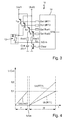
- a basic circuit concept according to the invention for a temperature measuring device 11 in a first basic embodiment of the invention is shown.
- the temperature measuring device 11 has a temperature sensor 13, in the present case a temperature-dependent resistor, which can form the temperature sensor shown in dashed lines.
- a series resistor 15 is connected, and in turn a switch 17, which is controlled via a select output of a microcontroller 19.
- the switch 17 switches between two measuring voltages U ref1 and U ref2 .
- the respective measuring voltage is given to one of the inputs of the microcontroller 19 before the series resistor 15, as well as the voltage across the temperature sensor 13.
- U RT is the temperature-dependent voltage resulting from the division ratio of the series resistor 15 and the resistance value of the temperature sensor 13.
- the voltage U ref is simultaneously the operating voltage of the voltage divider 15 and 13, through which the current I 1 and I 2 is specified.
- the self-heating of the temperature sensor 13 is dependent on the size of the current I 1 or I 2 , which is predetermined by the switching of U ref1 and U ref2 via the output Select and the switch 17.
- the voltage ratio U ref to U RT remains the same, and thus also the measurement result of U RT1 of the A / D converter in the microcontroller 19th
- a memory 21 is present in which certain expected or desired temperature curves are stored for the temperature sensor 13 and the temperature measuring device 11.
- An output STB of the microcontroller 19 goes to a transistor 24 as a switch, which in turn a relay 25 drives to switch loads.
- a heater 27 is driven or turned on or off, which is shown here as a heating resistor, including with regard to Fig. 10 even more is being done.
- a fryer 30 is shown as an exemplary electrical device having the temperature measuring device 11. Inside the deep fryer 30 is the heater 27, exemplified here as usual for such cases tubular heater. He is according to the Fig. 1 can be controlled by means of the relay 25, which in turn is controlled by the microcontroller 19.
- a temperature sensor or temperature sensor 13 of the temperature measuring device 11 is arranged in the fryer 30. This temperature sensor 13 detects the temperature in the fryer 30 or the frying fat therein to avoid overheating by the heater 27.
- Fig. 2a the course of the temperature T over the time t is shown. Straight through the actual temperature curve runs at the location of the temperature sensor 13, if it were not operated. Shown dashed is the temperature in the temperature sensor 13, which has the wavy course described above with the different amplitudes due to the different measurement voltages. This wavy curve is in the Fig. 2b shown alone and solid.
- a temperature measurement at the temperature sensor 13 is carried out with the first measuring voltage U ref1 by the switch 17 being controlled by the microcontroller 19 via the voltage U ref1 Series resistor 15 to the temperature sensor 13 applies.
- the switch 17 is switched over and the measurement voltage U ref2 is applied to the temperature sensor 13. Since the measuring voltage U ref1 is greater than the measuring voltage U ref2 , the increase in the temperature in the temperature sensor 13 between measuring time 1 and measuring time 2 is somewhat stronger.
- the course of the temperature up to the renewed measuring time 1 is detected. Since the second measuring voltage U ref2 is now smaller, the temperature drops again somewhat from the measuring time 2 to the measuring time 1. Thus, in each case the actual temperature can be measured at the time of measurement 1, under certain circumstances with an initially mentioned correction value.
- a control measurement is made.
- the temperature must be higher than at measurement time 1 before and after, that is, when measured again with the slightly lower measurement voltage U ref2 . This is the input called plausibility check in the temperature measuring device 11.
- the Fig. 2c shows the course of the temperatures, the lowest one from the Fig. 2a is.
- the mean temperature curve is that at U ref2 , and the top one is at U ref1 .
- the temperature difference between the two upper curves is ⁇ T1 and the one between the lower ones is ⁇ T2, see also the comments made at the beginning.
- the Fig. 3 shows the practical implementation of the circuit concept of Fig. 1 ,
- the switch 17 is here replaced by the transistors T u1 and T u2 and T r1 and T r2 . These four transistors are each switched by respective outputs of the microcontroller 19.
- the transistors T r1 and T r2 control the respective measurement voltage at the input of the microcontroller 19 via resistors R ref1 and R ref2 .
- a capacitor C int for the conversion times is provided, as well as a transistor T c .
- About the discharge switch T c is the integration capacitor for a time t clear Unload C int .
- the charging time t1 is stored in the microcontroller 19.
- the charging time t2 is also stored in the microcontroller 19.
- the temperature-dependent resistance of the temperature sensor 13 can now be calculated in the microcontroller 19 from the ratio R ref1 * t2 / t1. The procedure is the same with the branch U ref2 and R ref2 , ie with the second measuring voltage.
- Fig. 4 is shown in the diagram, the course of the voltage at the input of the microcontroller 19, both for the two voltages U 1 and U 2 and during the respective measurement times t 1 and t 2 .
- the resistance value of the temperature sensor 13 behaves like the resistance value of the respective reference resistor R ref1 or R ref2 multiplied by the ratio of the measuring time t 2 to the measuring time t 1 . If the capacitor C int is selected to be 22 ⁇ F and a PT1000 is used as the temperature sensor 13, a switching threshold of 54 ms results at 400 ° C.
- the alternative basic circuit concept of Fig. 5 has at the local temperature measuring device 111 on a first temperature sensor 113 and a second temperature sensor 113 '. These two temperature sensors can be combined in a single temperature sensor shown in dashed lines and, according to Fig. 10 , be arranged in the fryer, advantageously also in close proximity to each other to measure the same temperature.
- a series resistor 115 and a switch 117 for two measuring voltages U ref1 and R ref2 are provided.
- the switch 117 is in turn switched by the microcontroller 119, which also contains a memory 121.
- the microcontroller 119 To the right of the output STB of the microcontroller 119 closes accordingly Fig. 1 a switchable heater, which has not been shown here for the sake of clarity.
- the temperature measuring device 111 also has a further room temperature sensor 114, which also has a temperature-dependent resistance value. It serves to check the values of the temperature sensor 113 by determining the room temperature.
- the voltages across the temperature sensors 113 and 114 are applied via a multiplexer 122 to the corresponding input of the microcontroller 119.
- the two temperature sensors 113 and 113 ' form a sensor pair which is initially not electrically connected together in the temperature sensor. Each temperature measurement must be recorded separately.
- the room temperature sensor 114 serves as a reference resistance sensor, via which a calibration and a functional check of the temperature sensors 113 and 113 'are performed. For this purpose, it can be arranged on the same component carrier as the other circuit components, for example as the microcontroller 119.
- the multiplexer 122 serves to switch over the individual sensors 113, 113 'and 114 and can also be part of the microcontroller 119.
- Fig. 6 is in accord with Fig. 3 the practical implementation of the circuit concept of the temperature measuring device 111 shown.
- Fig. 7 is the corresponding time course of the voltage at the input of the microcontroller 119 during the two measurement times t1 and t 2 according to the Fig. 4 shown.
- a temperature measuring device 211 similar to Fig. 6 , two temperature sensors 213 and 213 'are provided. They are supplied via transistors T r1 and T r2 with measuring voltages, specifically 9 V and 3.3 V.
- a multiplexer 222 is integrated in addition to a memory 221, as well as a further transistor 232 together with an internal OP amplifier. An attached heater including switches accordingly Fig. 1 again is not shown. Both the multiplexer 222 for switching the sensor voltages U ref1 and U ref2 and the discharge switch 232 may be integrated in the microcontroller 219.
- Fig. 9 is also the course of the input voltage to the microcontroller 219 shown, both voltages U 2 and U 1 for the two measurement times t1 and t2.
- the two temperature sensors of Fig. 5/6 on the one hand and 8 on the other hand can be selected according to the criteria mentioned above, so should be different in different ways. Furthermore, it can be seen that in the microcontroller only one control for the heater is connected, see especially the Fig. 1 ,
Landscapes
- Physics & Mathematics (AREA)
- General Physics & Mathematics (AREA)
- Nonlinear Science (AREA)
- Measuring Temperature Or Quantity Of Heat (AREA)
- Frying-Pans Or Fryers (AREA)
- Control Of Resistance Heating (AREA)
Applications Claiming Priority (1)
| Application Number | Priority Date | Filing Date | Title |
|---|---|---|---|
| DE102012208125A DE102012208125A1 (de) | 2012-05-15 | 2012-05-15 | Temperaturmesseinrichtung, elektrisches Gerät mit einer solchen Temperaturmesseinrichtung und Verfahren zur Temperaturmessung |
Publications (3)
| Publication Number | Publication Date |
|---|---|
| EP2664905A2 true EP2664905A2 (fr) | 2013-11-20 |
| EP2664905A3 EP2664905A3 (fr) | 2015-01-21 |
| EP2664905B1 EP2664905B1 (fr) | 2016-08-24 |
Family
ID=48325539
Family Applications (1)
| Application Number | Title | Priority Date | Filing Date |
|---|---|---|---|
| EP13167708.0A Not-in-force EP2664905B1 (fr) | 2012-05-15 | 2013-05-14 | Dispositif de mesure de température, appareil électrique doté d'un tel dispositif de mesure de la température et procédé de mesure de la température |
Country Status (7)
| Country | Link |
|---|---|
| US (1) | US9304049B2 (fr) |
| EP (1) | EP2664905B1 (fr) |
| JP (1) | JP2013238601A (fr) |
| CN (1) | CN103424205A (fr) |
| DE (1) | DE102012208125A1 (fr) |
| ES (1) | ES2610740T3 (fr) |
| PL (1) | PL2664905T3 (fr) |
Cited By (6)
| Publication number | Priority date | Publication date | Assignee | Title |
|---|---|---|---|---|
| WO2015108465A1 (fr) * | 2014-01-17 | 2015-07-23 | Conflux Ab | Agencement et procédé de mesure de la température |
| NL2017179B1 (en) * | 2016-07-15 | 2017-07-17 | Intermodal Telematics B V | Temperature measuring circuit obviating calibration |
| WO2021058302A1 (fr) * | 2019-09-27 | 2021-04-01 | Valeo Siemens Eautomotive Germany Gmbh | Procédé et dispositif pour déterminer un élément d'information de température décrivant la température d'un détecteur de température de résistance, onduleur, véhicule et programme informatique |
| CN114396746A (zh) * | 2022-01-25 | 2022-04-26 | 烟台艾睿光电科技有限公司 | 用于制冷机的控制方法和控制系统 |
| US11579026B2 (en) * | 2019-05-21 | 2023-02-14 | Abb Schweiz Ag | Testing method for non-invasive temperature measuring instruments |
| US20230251142A1 (en) * | 2022-02-07 | 2023-08-10 | Hyundai Mobis Co., Ltd. | Temperature sensing apparatus |
Families Citing this family (6)
| Publication number | Priority date | Publication date | Assignee | Title |
|---|---|---|---|---|
| JP5215060B2 (ja) * | 2008-07-02 | 2013-06-19 | テルモ株式会社 | 電子体温計及び作動制御方法 |
| DE102013216256A1 (de) | 2013-08-15 | 2014-09-11 | E.G.O. Elektro-Gerätebau GmbH | Temperaturfühleinrichtung und Temperaturregler |
| CN107960832B (zh) * | 2016-10-19 | 2020-09-04 | 佛山市顺德区美的电热电器制造有限公司 | 烹饪设备及其控制方法和控制装置 |
| US10761041B2 (en) * | 2017-11-21 | 2020-09-01 | Watlow Electric Manufacturing Company | Multi-parallel sensor array system |
| EP3490052B1 (fr) | 2017-11-24 | 2019-10-02 | Samsung SDI Co., Ltd. | Procédé de test et circuit de contact thermique de capteur de température |
| KR20220167988A (ko) * | 2021-06-15 | 2022-12-22 | 주식회사 엘지에너지솔루션 | 마이크로 컨트롤러의 온도 측정을 위한 배터리 관리장치의 구성 및 그 제어방법 |
Citations (3)
| Publication number | Priority date | Publication date | Assignee | Title |
|---|---|---|---|---|
| DE102004035014A1 (de) | 2004-07-20 | 2006-02-16 | Joachim Krieger | Anordnung von Sensorelementen zum zuverlässigen Messen einer Temperatur |
| DE69733138T2 (de) | 1996-08-23 | 2006-02-23 | Accutru International Corp., Kingwood | Selbstprüfender temperatursensor |
| DE202009003889U1 (de) | 2009-03-19 | 2009-05-28 | Rational Ag | Gargerät |
Family Cites Families (18)
| Publication number | Priority date | Publication date | Assignee | Title |
|---|---|---|---|---|
| CA925586A (en) * | 1969-12-11 | 1973-05-01 | Miyamoto Mamoru | Engine temperature warning device |
| US3728702A (en) | 1969-12-11 | 1973-04-17 | Matsushita Electric Industrial Co Ltd | Temperature alarm utilizing paired positive and negative coefficient thermistors |
| DE2841783A1 (de) * | 1978-09-26 | 1980-04-03 | Bosch Siemens Hausgeraete | Einstellbarer elektronischer temperaturregler, insbesondere fuer gefriergeraete o.dgl. |
| DE3933311A1 (de) * | 1989-10-05 | 1991-04-18 | Endress Hauser Gmbh Co | Temperaturmessschaltung |
| AT399235B (de) | 1992-12-24 | 1995-04-25 | Vaillant Gmbh | Verfahren zur funktionskontrolle eines temperaturfühlers |
| DE4312395A1 (de) * | 1993-04-16 | 1994-10-20 | Gsf Forschungszentrum Umwelt | Verfahren zur Erhöhung der Meßgenauigkeit von Widerstandsthermometern |
| DE4312394A1 (de) * | 1993-04-16 | 1994-10-20 | Gsf Forschungszentrum Umwelt | Widerstandsthermometer |
| US6519546B1 (en) * | 1996-11-07 | 2003-02-11 | Rosemount Inc. | Auto correcting temperature transmitter with resistance based sensor |
| US20040004994A1 (en) * | 2002-07-03 | 2004-01-08 | Dolly Wu | Temperature sensing read-out system for an integrated circuit |
| US7310213B2 (en) * | 2003-09-26 | 2007-12-18 | Matsushita Electric Industrial Co., Ltd. | Semiconductor device provided with overheat protection circuit and electronic circuit using the same |
| EP1602907A1 (fr) * | 2004-05-31 | 2005-12-07 | Gefran Sensori S.r.l. | Correction automatique d'un capteur par un microprocesseur rétroactif |
| KR100672342B1 (ko) * | 2006-01-25 | 2007-01-24 | 엘지전자 주식회사 | 조리기기의 온도센서회로 자동 제어방법 |
| JP4700016B2 (ja) * | 2007-02-14 | 2011-06-15 | プライムアースEvエナジー株式会社 | 制御機能付き回路、及び、その検査方法 |
| US8267578B2 (en) * | 2009-02-04 | 2012-09-18 | Schlumberger Technology Corporation | Methods and systems for temperature compensated temperature measurements |
| JP5219906B2 (ja) * | 2009-04-07 | 2013-06-26 | キヤノン株式会社 | 温度計測装置、温度計測方法、露光装置、及びデバイス製造方法 |
| JP2010261860A (ja) | 2009-05-08 | 2010-11-18 | Shibaura Electronics Co Ltd | 温度センサ及び温度センサシステム |
| JP5055349B2 (ja) * | 2009-12-28 | 2012-10-24 | 日立オートモティブシステムズ株式会社 | 熱式ガスセンサ |
| EP2629075A1 (fr) * | 2012-02-20 | 2013-08-21 | Sony Ericsson Mobile Communications AB | Procédé pour déterminer une valeur de détecteur |
-
2012
- 2012-05-15 DE DE102012208125A patent/DE102012208125A1/de not_active Ceased
-
2013
- 2013-05-14 US US13/894,196 patent/US9304049B2/en not_active Expired - Fee Related
- 2013-05-14 PL PL13167708T patent/PL2664905T3/pl unknown
- 2013-05-14 ES ES13167708.0T patent/ES2610740T3/es active Active
- 2013-05-14 EP EP13167708.0A patent/EP2664905B1/fr not_active Not-in-force
- 2013-05-15 JP JP2013102910A patent/JP2013238601A/ja active Pending
- 2013-05-15 CN CN2013102526943A patent/CN103424205A/zh active Pending
Patent Citations (3)
| Publication number | Priority date | Publication date | Assignee | Title |
|---|---|---|---|---|
| DE69733138T2 (de) | 1996-08-23 | 2006-02-23 | Accutru International Corp., Kingwood | Selbstprüfender temperatursensor |
| DE102004035014A1 (de) | 2004-07-20 | 2006-02-16 | Joachim Krieger | Anordnung von Sensorelementen zum zuverlässigen Messen einer Temperatur |
| DE202009003889U1 (de) | 2009-03-19 | 2009-05-28 | Rational Ag | Gargerät |
Cited By (8)
| Publication number | Priority date | Publication date | Assignee | Title |
|---|---|---|---|---|
| WO2015108465A1 (fr) * | 2014-01-17 | 2015-07-23 | Conflux Ab | Agencement et procédé de mesure de la température |
| NL2017179B1 (en) * | 2016-07-15 | 2017-07-17 | Intermodal Telematics B V | Temperature measuring circuit obviating calibration |
| WO2018012965A1 (fr) * | 2016-07-15 | 2018-01-18 | Intermodal Telematics B.V. | Circuit de mesure de température ne nécessitant pas d'étalonnage |
| US11579026B2 (en) * | 2019-05-21 | 2023-02-14 | Abb Schweiz Ag | Testing method for non-invasive temperature measuring instruments |
| WO2021058302A1 (fr) * | 2019-09-27 | 2021-04-01 | Valeo Siemens Eautomotive Germany Gmbh | Procédé et dispositif pour déterminer un élément d'information de température décrivant la température d'un détecteur de température de résistance, onduleur, véhicule et programme informatique |
| CN114396746A (zh) * | 2022-01-25 | 2022-04-26 | 烟台艾睿光电科技有限公司 | 用于制冷机的控制方法和控制系统 |
| US20230251142A1 (en) * | 2022-02-07 | 2023-08-10 | Hyundai Mobis Co., Ltd. | Temperature sensing apparatus |
| US12405172B2 (en) * | 2022-02-07 | 2025-09-02 | Hyundai Mobis Co., Ltd. | Temperature sensing apparatus |
Also Published As
| Publication number | Publication date |
|---|---|
| US20130308684A1 (en) | 2013-11-21 |
| EP2664905B1 (fr) | 2016-08-24 |
| DE102012208125A1 (de) | 2013-11-21 |
| EP2664905A3 (fr) | 2015-01-21 |
| CN103424205A (zh) | 2013-12-04 |
| ES2610740T3 (es) | 2017-05-03 |
| PL2664905T3 (pl) | 2017-02-28 |
| JP2013238601A (ja) | 2013-11-28 |
| US9304049B2 (en) | 2016-04-05 |
Similar Documents
| Publication | Publication Date | Title |
|---|---|---|
| EP2664905B1 (fr) | Dispositif de mesure de température, appareil électrique doté d'un tel dispositif de mesure de la température et procédé de mesure de la température | |
| EP3417672B1 (fr) | Dispositif electrique, en particulier chauffeur electrique, ainsi qu'un dispositif et une methode de controle d'un dispositif electrique | |
| EP3199876B1 (fr) | Procédé et dispositif destinés à influencer un réglage de chauffage | |
| DE102015108888B4 (de) | Überhitzungserkennungsvorrichtung für einen Elektromotor, ausgestattet mit mehreren PTC Thermistoren | |
| DE69223310T2 (de) | Schaltkreis zur Feuchtigkeitserfassung | |
| DE102012219244A1 (de) | Verfahren und Vorrichtung zur Leistungssteuerung eines elektrischen Verbrauchers | |
| EP1989922A1 (fr) | Procédé et dispositif de reconaissance d'une sonde de température raccordé à une commande | |
| DE102014216610A1 (de) | Überwachung einer Spule | |
| EP2840404A1 (fr) | Chauffe-eau électrique instantané à fil nu et procédé de commande de celui-ci | |
| EP2805869B1 (fr) | Dispositif de chauffage pour des véhicules automobiles, chauffage de siège et chauffage de volant doté d'un tel dispositif de chauffage et procédé de commande de la température d'un dispositif de chauffage pour des véhicules automobiles | |
| WO2008046852A1 (fr) | Procédé pour la protection d'un élément chauffant ainsi que dispositif de chauffage | |
| DE3118399C2 (de) | Anordnung zur fühlerlosen Temperaturermittlung bei einem Herd | |
| DE102012214717A1 (de) | Verfahren und Vorrichtung zur Leistungssteuerung oder Spannungssteuerung eines elektrischen Verbrauchers | |
| DE102014219130A1 (de) | Diagnoseschaltung und Verfahren zum Betreiben einer Diagnoseschaltung | |
| DE4124187C1 (en) | Temp. regulating circuitry for electrical heating element - uses current measuring resistor and reference voltage forming divider consisting of ohmic resistors in series with element | |
| DE10115715B4 (de) | Sensor und Verfahren zur Erfassung von Meßgrößen und physikalischen Parametern | |
| WO2021058302A1 (fr) | Procédé et dispositif pour déterminer un élément d'information de température décrivant la température d'un détecteur de température de résistance, onduleur, véhicule et programme informatique | |
| EP2639511B1 (fr) | Procédé destiné au fonctionnement d'un appareil de cuisson avec thermomètre à rôti pouvant être connecté et appareil de cuisson | |
| DE102016105506A1 (de) | Temperaturmessvorrichtung | |
| DE102016200334A1 (de) | Temperaturmeßschaltung für ein Haushaltsgerät | |
| DE102006038832A1 (de) | Verfahren sowie Schaltungsanordnung zum Steuern wenigstens eines Heizelementes eines Heizgerätes | |
| EP1768461B1 (fr) | Méthode pour générer, traiter et évaluer un signal en correlation avec la température, et dispositif correspondant | |
| EP2826147A1 (fr) | Convertisseur a/n à intégration | |
| DE19707664A1 (de) | Vorrichtung und Verfahren zur Steuerung oder Regelung der Temperatur von beheizten Flächen | |
| DE102011108991A1 (de) | Leitung für Fluide mit einem Heizelement und Verfahren zum Steuern eines Heizelementes zur Erwärmung einer fluidführenden Leitung |
Legal Events
| Date | Code | Title | Description |
|---|---|---|---|
| PUAI | Public reference made under article 153(3) epc to a published international application that has entered the european phase |
Free format text: ORIGINAL CODE: 0009012 |
|
| AK | Designated contracting states |
Kind code of ref document: A2 Designated state(s): AL AT BE BG CH CY CZ DE DK EE ES FI FR GB GR HR HU IE IS IT LI LT LU LV MC MK MT NL NO PL PT RO RS SE SI SK SM TR |
|
| AX | Request for extension of the european patent |
Extension state: BA ME |
|
| PUAL | Search report despatched |
Free format text: ORIGINAL CODE: 0009013 |
|
| AK | Designated contracting states |
Kind code of ref document: A3 Designated state(s): AL AT BE BG CH CY CZ DE DK EE ES FI FR GB GR HR HU IE IS IT LI LT LU LV MC MK MT NL NO PL PT RO RS SE SI SK SM TR |
|
| AX | Request for extension of the european patent |
Extension state: BA ME |
|
| RIC1 | Information provided on ipc code assigned before grant |
Ipc: G01K 7/20 20060101AFI20141215BHEP |
|
| 17P | Request for examination filed |
Effective date: 20150708 |
|
| RBV | Designated contracting states (corrected) |
Designated state(s): AL AT BE BG CH CY CZ DE DK EE ES FI FR GB GR HR HU IE IS IT LI LT LU LV MC MK MT NL NO PL PT RO RS SE SI SK SM TR |
|
| 17Q | First examination report despatched |
Effective date: 20151127 |
|
| GRAP | Despatch of communication of intention to grant a patent |
Free format text: ORIGINAL CODE: EPIDOSNIGR1 |
|
| INTG | Intention to grant announced |
Effective date: 20160407 |
|
| GRAS | Grant fee paid |
Free format text: ORIGINAL CODE: EPIDOSNIGR3 |
|
| GRAA | (expected) grant |
Free format text: ORIGINAL CODE: 0009210 |
|
| AK | Designated contracting states |
Kind code of ref document: B1 Designated state(s): AL AT BE BG CH CY CZ DE DK EE ES FI FR GB GR HR HU IE IS IT LI LT LU LV MC MK MT NL NO PL PT RO RS SE SI SK SM TR |
|
| REG | Reference to a national code |
Ref country code: GB Ref legal event code: FG4D Free format text: NOT ENGLISH |
|
| REG | Reference to a national code |
Ref country code: CH Ref legal event code: EP |
|
| REG | Reference to a national code |
Ref country code: AT Ref legal event code: REF Ref document number: 823523 Country of ref document: AT Kind code of ref document: T Effective date: 20160915 |
|
| REG | Reference to a national code |
Ref country code: IE Ref legal event code: FG4D Free format text: LANGUAGE OF EP DOCUMENT: GERMAN |
|
| REG | Reference to a national code |
Ref country code: DE Ref legal event code: R096 Ref document number: 502013004124 Country of ref document: DE |
|
| REG | Reference to a national code |
Ref country code: LT Ref legal event code: MG4D |
|
| REG | Reference to a national code |
Ref country code: NL Ref legal event code: MP Effective date: 20160824 |
|
| PG25 | Lapsed in a contracting state [announced via postgrant information from national office to epo] |
Ref country code: HR Free format text: LAPSE BECAUSE OF FAILURE TO SUBMIT A TRANSLATION OF THE DESCRIPTION OR TO PAY THE FEE WITHIN THE PRESCRIBED TIME-LIMIT Effective date: 20160824 Ref country code: NO Free format text: LAPSE BECAUSE OF FAILURE TO SUBMIT A TRANSLATION OF THE DESCRIPTION OR TO PAY THE FEE WITHIN THE PRESCRIBED TIME-LIMIT Effective date: 20161124 Ref country code: FI Free format text: LAPSE BECAUSE OF FAILURE TO SUBMIT A TRANSLATION OF THE DESCRIPTION OR TO PAY THE FEE WITHIN THE PRESCRIBED TIME-LIMIT Effective date: 20160824 Ref country code: LT Free format text: LAPSE BECAUSE OF FAILURE TO SUBMIT A TRANSLATION OF THE DESCRIPTION OR TO PAY THE FEE WITHIN THE PRESCRIBED TIME-LIMIT Effective date: 20160824 Ref country code: RS Free format text: LAPSE BECAUSE OF FAILURE TO SUBMIT A TRANSLATION OF THE DESCRIPTION OR TO PAY THE FEE WITHIN THE PRESCRIBED TIME-LIMIT Effective date: 20160824 Ref country code: NL Free format text: LAPSE BECAUSE OF FAILURE TO SUBMIT A TRANSLATION OF THE DESCRIPTION OR TO PAY THE FEE WITHIN THE PRESCRIBED TIME-LIMIT Effective date: 20160824 |
|
| PG25 | Lapsed in a contracting state [announced via postgrant information from national office to epo] |
Ref country code: SE Free format text: LAPSE BECAUSE OF FAILURE TO SUBMIT A TRANSLATION OF THE DESCRIPTION OR TO PAY THE FEE WITHIN THE PRESCRIBED TIME-LIMIT Effective date: 20160824 Ref country code: PT Free format text: LAPSE BECAUSE OF FAILURE TO SUBMIT A TRANSLATION OF THE DESCRIPTION OR TO PAY THE FEE WITHIN THE PRESCRIBED TIME-LIMIT Effective date: 20161226 Ref country code: GR Free format text: LAPSE BECAUSE OF FAILURE TO SUBMIT A TRANSLATION OF THE DESCRIPTION OR TO PAY THE FEE WITHIN THE PRESCRIBED TIME-LIMIT Effective date: 20161125 Ref country code: LV Free format text: LAPSE BECAUSE OF FAILURE TO SUBMIT A TRANSLATION OF THE DESCRIPTION OR TO PAY THE FEE WITHIN THE PRESCRIBED TIME-LIMIT Effective date: 20160824 |
|
| PG25 | Lapsed in a contracting state [announced via postgrant information from national office to epo] |
Ref country code: EE Free format text: LAPSE BECAUSE OF FAILURE TO SUBMIT A TRANSLATION OF THE DESCRIPTION OR TO PAY THE FEE WITHIN THE PRESCRIBED TIME-LIMIT Effective date: 20160824 Ref country code: RO Free format text: LAPSE BECAUSE OF FAILURE TO SUBMIT A TRANSLATION OF THE DESCRIPTION OR TO PAY THE FEE WITHIN THE PRESCRIBED TIME-LIMIT Effective date: 20160824 |
|
| REG | Reference to a national code |
Ref country code: ES Ref legal event code: FG2A Ref document number: 2610740 Country of ref document: ES Kind code of ref document: T3 Effective date: 20170503 |
|
| REG | Reference to a national code |
Ref country code: FR Ref legal event code: PLFP Year of fee payment: 5 |
|
| REG | Reference to a national code |
Ref country code: DE Ref legal event code: R097 Ref document number: 502013004124 Country of ref document: DE |
|
| PG25 | Lapsed in a contracting state [announced via postgrant information from national office to epo] |
Ref country code: SM Free format text: LAPSE BECAUSE OF FAILURE TO SUBMIT A TRANSLATION OF THE DESCRIPTION OR TO PAY THE FEE WITHIN THE PRESCRIBED TIME-LIMIT Effective date: 20160824 Ref country code: BG Free format text: LAPSE BECAUSE OF FAILURE TO SUBMIT A TRANSLATION OF THE DESCRIPTION OR TO PAY THE FEE WITHIN THE PRESCRIBED TIME-LIMIT Effective date: 20161124 Ref country code: DK Free format text: LAPSE BECAUSE OF FAILURE TO SUBMIT A TRANSLATION OF THE DESCRIPTION OR TO PAY THE FEE WITHIN THE PRESCRIBED TIME-LIMIT Effective date: 20160824 Ref country code: SK Free format text: LAPSE BECAUSE OF FAILURE TO SUBMIT A TRANSLATION OF THE DESCRIPTION OR TO PAY THE FEE WITHIN THE PRESCRIBED TIME-LIMIT Effective date: 20160824 Ref country code: CZ Free format text: LAPSE BECAUSE OF FAILURE TO SUBMIT A TRANSLATION OF THE DESCRIPTION OR TO PAY THE FEE WITHIN THE PRESCRIBED TIME-LIMIT Effective date: 20160824 |
|
| PLBE | No opposition filed within time limit |
Free format text: ORIGINAL CODE: 0009261 |
|
| STAA | Information on the status of an ep patent application or granted ep patent |
Free format text: STATUS: NO OPPOSITION FILED WITHIN TIME LIMIT |
|
| PGFP | Annual fee paid to national office [announced via postgrant information from national office to epo] |
Ref country code: FR Payment date: 20170522 Year of fee payment: 5 |
|
| 26N | No opposition filed |
Effective date: 20170526 |
|
| PG25 | Lapsed in a contracting state [announced via postgrant information from national office to epo] |
Ref country code: LU Free format text: LAPSE BECAUSE OF NON-PAYMENT OF DUE FEES Effective date: 20170531 Ref country code: SI Free format text: LAPSE BECAUSE OF FAILURE TO SUBMIT A TRANSLATION OF THE DESCRIPTION OR TO PAY THE FEE WITHIN THE PRESCRIBED TIME-LIMIT Effective date: 20160824 |
|
| PGFP | Annual fee paid to national office [announced via postgrant information from national office to epo] |
Ref country code: PL Payment date: 20170406 Year of fee payment: 5 Ref country code: ES Payment date: 20170601 Year of fee payment: 5 Ref country code: IT Payment date: 20170524 Year of fee payment: 5 |
|
| REG | Reference to a national code |
Ref country code: CH Ref legal event code: PL |
|
| GBPC | Gb: european patent ceased through non-payment of renewal fee |
Effective date: 20170514 |
|
| PG25 | Lapsed in a contracting state [announced via postgrant information from national office to epo] |
Ref country code: MC Free format text: LAPSE BECAUSE OF FAILURE TO SUBMIT A TRANSLATION OF THE DESCRIPTION OR TO PAY THE FEE WITHIN THE PRESCRIBED TIME-LIMIT Effective date: 20160824 |
|
| REG | Reference to a national code |
Ref country code: IE Ref legal event code: MM4A |
|
| PG25 | Lapsed in a contracting state [announced via postgrant information from national office to epo] |
Ref country code: CH Free format text: LAPSE BECAUSE OF NON-PAYMENT OF DUE FEES Effective date: 20170531 Ref country code: LI Free format text: LAPSE BECAUSE OF NON-PAYMENT OF DUE FEES Effective date: 20170531 |
|
| PG25 | Lapsed in a contracting state [announced via postgrant information from national office to epo] |
Ref country code: LU Free format text: LAPSE BECAUSE OF NON-PAYMENT OF DUE FEES Effective date: 20170514 |
|
| REG | Reference to a national code |
Ref country code: BE Ref legal event code: MM Effective date: 20170531 |
|
| PG25 | Lapsed in a contracting state [announced via postgrant information from national office to epo] |
Ref country code: GB Free format text: LAPSE BECAUSE OF NON-PAYMENT OF DUE FEES Effective date: 20170514 Ref country code: IE Free format text: LAPSE BECAUSE OF NON-PAYMENT OF DUE FEES Effective date: 20170514 |
|
| PG25 | Lapsed in a contracting state [announced via postgrant information from national office to epo] |
Ref country code: BE Free format text: LAPSE BECAUSE OF NON-PAYMENT OF DUE FEES Effective date: 20170531 |
|
| PG25 | Lapsed in a contracting state [announced via postgrant information from national office to epo] |
Ref country code: MT Free format text: LAPSE BECAUSE OF FAILURE TO SUBMIT A TRANSLATION OF THE DESCRIPTION OR TO PAY THE FEE WITHIN THE PRESCRIBED TIME-LIMIT Effective date: 20160824 |
|
| PG25 | Lapsed in a contracting state [announced via postgrant information from national office to epo] |
Ref country code: AL Free format text: LAPSE BECAUSE OF FAILURE TO SUBMIT A TRANSLATION OF THE DESCRIPTION OR TO PAY THE FEE WITHIN THE PRESCRIBED TIME-LIMIT Effective date: 20160824 |
|
| PG25 | Lapsed in a contracting state [announced via postgrant information from national office to epo] |
Ref country code: FR Free format text: LAPSE BECAUSE OF NON-PAYMENT OF DUE FEES Effective date: 20180531 Ref country code: IT Free format text: LAPSE BECAUSE OF NON-PAYMENT OF DUE FEES Effective date: 20180514 |
|
| PG25 | Lapsed in a contracting state [announced via postgrant information from national office to epo] |
Ref country code: HU Free format text: LAPSE BECAUSE OF FAILURE TO SUBMIT A TRANSLATION OF THE DESCRIPTION OR TO PAY THE FEE WITHIN THE PRESCRIBED TIME-LIMIT; INVALID AB INITIO Effective date: 20130514 |
|
| REG | Reference to a national code |
Ref country code: AT Ref legal event code: MM01 Ref document number: 823523 Country of ref document: AT Kind code of ref document: T Effective date: 20180514 |
|
| REG | Reference to a national code |
Ref country code: ES Ref legal event code: FD2A Effective date: 20190913 |
|
| PG25 | Lapsed in a contracting state [announced via postgrant information from national office to epo] |
Ref country code: ES Free format text: LAPSE BECAUSE OF NON-PAYMENT OF DUE FEES Effective date: 20180515 Ref country code: AT Free format text: LAPSE BECAUSE OF NON-PAYMENT OF DUE FEES Effective date: 20180514 Ref country code: CY Free format text: LAPSE BECAUSE OF NON-PAYMENT OF DUE FEES Effective date: 20160824 |
|
| PG25 | Lapsed in a contracting state [announced via postgrant information from national office to epo] |
Ref country code: MK Free format text: LAPSE BECAUSE OF FAILURE TO SUBMIT A TRANSLATION OF THE DESCRIPTION OR TO PAY THE FEE WITHIN THE PRESCRIBED TIME-LIMIT Effective date: 20160824 |
|
| PG25 | Lapsed in a contracting state [announced via postgrant information from national office to epo] |
Ref country code: PL Free format text: LAPSE BECAUSE OF NON-PAYMENT OF DUE FEES Effective date: 20180514 |
|
| PG25 | Lapsed in a contracting state [announced via postgrant information from national office to epo] |
Ref country code: TR Free format text: LAPSE BECAUSE OF FAILURE TO SUBMIT A TRANSLATION OF THE DESCRIPTION OR TO PAY THE FEE WITHIN THE PRESCRIBED TIME-LIMIT Effective date: 20160824 |
|
| PG25 | Lapsed in a contracting state [announced via postgrant information from national office to epo] |
Ref country code: IS Free format text: LAPSE BECAUSE OF FAILURE TO SUBMIT A TRANSLATION OF THE DESCRIPTION OR TO PAY THE FEE WITHIN THE PRESCRIBED TIME-LIMIT Effective date: 20161224 |
|
| PGFP | Annual fee paid to national office [announced via postgrant information from national office to epo] |
Ref country code: DE Payment date: 20220519 Year of fee payment: 10 |
|
| REG | Reference to a national code |
Ref country code: DE Ref legal event code: R119 Ref document number: 502013004124 Country of ref document: DE |
|
| PG25 | Lapsed in a contracting state [announced via postgrant information from national office to epo] |
Ref country code: DE Free format text: LAPSE BECAUSE OF NON-PAYMENT OF DUE FEES Effective date: 20231201 |