EP2665152A2 - Ladesystem - Google Patents
Ladesystem Download PDFInfo
- Publication number
- EP2665152A2 EP2665152A2 EP13153647.6A EP13153647A EP2665152A2 EP 2665152 A2 EP2665152 A2 EP 2665152A2 EP 13153647 A EP13153647 A EP 13153647A EP 2665152 A2 EP2665152 A2 EP 2665152A2
- Authority
- EP
- European Patent Office
- Prior art keywords
- phase
- charging system
- converting
- circuit
- plural
- Prior art date
- Legal status (The legal status is an assumption and is not a legal conclusion. Google has not performed a legal analysis and makes no representation as to the accuracy of the status listed.)
- Withdrawn
Links
Images


Classifications
-
- B—PERFORMING OPERATIONS; TRANSPORTING
- B60—VEHICLES IN GENERAL
- B60L—PROPULSION OF ELECTRICALLY-PROPELLED VEHICLES; SUPPLYING ELECTRIC POWER FOR AUXILIARY EQUIPMENT OF ELECTRICALLY-PROPELLED VEHICLES; ELECTRODYNAMIC BRAKE SYSTEMS FOR VEHICLES IN GENERAL; MAGNETIC SUSPENSION OR LEVITATION FOR VEHICLES; MONITORING OPERATING VARIABLES OF ELECTRICALLY-PROPELLED VEHICLES; ELECTRIC SAFETY DEVICES FOR ELECTRICALLY-PROPELLED VEHICLES
- B60L53/00—Methods of charging batteries, specially adapted for electric vehicles; Charging stations or on-board charging equipment therefor; Exchange of energy storage elements in electric vehicles
- B60L53/20—Methods of charging batteries, specially adapted for electric vehicles; Charging stations or on-board charging equipment therefor; Exchange of energy storage elements in electric vehicles characterised by converters located in the vehicle
- B60L53/22—Constructional details or arrangements of charging converters specially adapted for charging electric vehicles
-
- B—PERFORMING OPERATIONS; TRANSPORTING
- B60—VEHICLES IN GENERAL
- B60L—PROPULSION OF ELECTRICALLY-PROPELLED VEHICLES; SUPPLYING ELECTRIC POWER FOR AUXILIARY EQUIPMENT OF ELECTRICALLY-PROPELLED VEHICLES; ELECTRODYNAMIC BRAKE SYSTEMS FOR VEHICLES IN GENERAL; MAGNETIC SUSPENSION OR LEVITATION FOR VEHICLES; MONITORING OPERATING VARIABLES OF ELECTRICALLY-PROPELLED VEHICLES; ELECTRIC SAFETY DEVICES FOR ELECTRICALLY-PROPELLED VEHICLES
- B60L53/00—Methods of charging batteries, specially adapted for electric vehicles; Charging stations or on-board charging equipment therefor; Exchange of energy storage elements in electric vehicles
- B60L53/30—Constructional details of charging stations
- B60L53/305—Communication interfaces
-
- B—PERFORMING OPERATIONS; TRANSPORTING
- B60—VEHICLES IN GENERAL
- B60L—PROPULSION OF ELECTRICALLY-PROPELLED VEHICLES; SUPPLYING ELECTRIC POWER FOR AUXILIARY EQUIPMENT OF ELECTRICALLY-PROPELLED VEHICLES; ELECTRODYNAMIC BRAKE SYSTEMS FOR VEHICLES IN GENERAL; MAGNETIC SUSPENSION OR LEVITATION FOR VEHICLES; MONITORING OPERATING VARIABLES OF ELECTRICALLY-PROPELLED VEHICLES; ELECTRIC SAFETY DEVICES FOR ELECTRICALLY-PROPELLED VEHICLES
- B60L53/00—Methods of charging batteries, specially adapted for electric vehicles; Charging stations or on-board charging equipment therefor; Exchange of energy storage elements in electric vehicles
- B60L53/60—Monitoring or controlling charging stations
- B60L53/68—Off-site monitoring or control, e.g. remote control
-
- H—ELECTRICITY
- H02—GENERATION; CONVERSION OR DISTRIBUTION OF ELECTRIC POWER
- H02J—ELECTRIC POWER NETWORKS; CIRCUIT ARRANGEMENTS OR SYSTEMS FOR SUPPLYING OR DISTRIBUTING ELECTRIC POWER; SYSTEMS FOR STORING ELECTRIC ENERGY
- H02J7/00—Circuit arrangements for charging or discharging batteries or for supplying loads from batteries
- H02J7/02—Circuit arrangements for charging or discharging batteries or for supplying loads from batteries for charging batteries from AC mains by converters
-
- B—PERFORMING OPERATIONS; TRANSPORTING
- B60—VEHICLES IN GENERAL
- B60L—PROPULSION OF ELECTRICALLY-PROPELLED VEHICLES; SUPPLYING ELECTRIC POWER FOR AUXILIARY EQUIPMENT OF ELECTRICALLY-PROPELLED VEHICLES; ELECTRODYNAMIC BRAKE SYSTEMS FOR VEHICLES IN GENERAL; MAGNETIC SUSPENSION OR LEVITATION FOR VEHICLES; MONITORING OPERATING VARIABLES OF ELECTRICALLY-PROPELLED VEHICLES; ELECTRIC SAFETY DEVICES FOR ELECTRICALLY-PROPELLED VEHICLES
- B60L2210/00—Converter types
- B60L2210/10—DC to DC converters
-
- B—PERFORMING OPERATIONS; TRANSPORTING
- B60—VEHICLES IN GENERAL
- B60L—PROPULSION OF ELECTRICALLY-PROPELLED VEHICLES; SUPPLYING ELECTRIC POWER FOR AUXILIARY EQUIPMENT OF ELECTRICALLY-PROPELLED VEHICLES; ELECTRODYNAMIC BRAKE SYSTEMS FOR VEHICLES IN GENERAL; MAGNETIC SUSPENSION OR LEVITATION FOR VEHICLES; MONITORING OPERATING VARIABLES OF ELECTRICALLY-PROPELLED VEHICLES; ELECTRIC SAFETY DEVICES FOR ELECTRICALLY-PROPELLED VEHICLES
- B60L2210/00—Converter types
- B60L2210/30—AC to DC converters
-
- B—PERFORMING OPERATIONS; TRANSPORTING
- B60—VEHICLES IN GENERAL
- B60L—PROPULSION OF ELECTRICALLY-PROPELLED VEHICLES; SUPPLYING ELECTRIC POWER FOR AUXILIARY EQUIPMENT OF ELECTRICALLY-PROPELLED VEHICLES; ELECTRODYNAMIC BRAKE SYSTEMS FOR VEHICLES IN GENERAL; MAGNETIC SUSPENSION OR LEVITATION FOR VEHICLES; MONITORING OPERATING VARIABLES OF ELECTRICALLY-PROPELLED VEHICLES; ELECTRIC SAFETY DEVICES FOR ELECTRICALLY-PROPELLED VEHICLES
- B60L2210/00—Converter types
- B60L2210/40—DC to AC converters
-
- H—ELECTRICITY
- H02—GENERATION; CONVERSION OR DISTRIBUTION OF ELECTRIC POWER
- H02J—ELECTRIC POWER NETWORKS; CIRCUIT ARRANGEMENTS OR SYSTEMS FOR SUPPLYING OR DISTRIBUTING ELECTRIC POWER; SYSTEMS FOR STORING ELECTRIC ENERGY
- H02J2207/00—Details of circuit arrangements for charging or discharging batteries or supplying loads from batteries
- H02J2207/20—Charging or discharging characterised by the power electronics converter
-
- H—ELECTRICITY
- H02—GENERATION; CONVERSION OR DISTRIBUTION OF ELECTRIC POWER
- H02M—APPARATUS FOR CONVERSION BETWEEN AC AND AC, BETWEEN AC AND DC, OR BETWEEN DC AND DC, AND FOR USE WITH MAINS OR SIMILAR POWER SUPPLY SYSTEMS; CONVERSION OF DC OR AC INPUT POWER INTO SURGE OUTPUT POWER; CONTROL OR REGULATION THEREOF
- H02M1/00—Details of apparatus for conversion
- H02M1/0067—Converter structures employing plural converter units, other than for parallel operation of the units on a single load
- H02M1/007—Plural converter units in cascade
-
- Y—GENERAL TAGGING OF NEW TECHNOLOGICAL DEVELOPMENTS; GENERAL TAGGING OF CROSS-SECTIONAL TECHNOLOGIES SPANNING OVER SEVERAL SECTIONS OF THE IPC; TECHNICAL SUBJECTS COVERED BY FORMER USPC CROSS-REFERENCE ART COLLECTIONS [XRACs] AND DIGESTS
- Y02—TECHNOLOGIES OR APPLICATIONS FOR MITIGATION OR ADAPTATION AGAINST CLIMATE CHANGE
- Y02T—CLIMATE CHANGE MITIGATION TECHNOLOGIES RELATED TO TRANSPORTATION
- Y02T10/00—Road transport of goods or passengers
- Y02T10/60—Other road transportation technologies with climate change mitigation effect
- Y02T10/70—Energy storage systems for electromobility, e.g. batteries
-
- Y—GENERAL TAGGING OF NEW TECHNOLOGICAL DEVELOPMENTS; GENERAL TAGGING OF CROSS-SECTIONAL TECHNOLOGIES SPANNING OVER SEVERAL SECTIONS OF THE IPC; TECHNICAL SUBJECTS COVERED BY FORMER USPC CROSS-REFERENCE ART COLLECTIONS [XRACs] AND DIGESTS
- Y02—TECHNOLOGIES OR APPLICATIONS FOR MITIGATION OR ADAPTATION AGAINST CLIMATE CHANGE
- Y02T—CLIMATE CHANGE MITIGATION TECHNOLOGIES RELATED TO TRANSPORTATION
- Y02T10/00—Road transport of goods or passengers
- Y02T10/60—Other road transportation technologies with climate change mitigation effect
- Y02T10/7072—Electromobility specific charging systems or methods for batteries, ultracapacitors, supercapacitors or double-layer capacitors
-
- Y—GENERAL TAGGING OF NEW TECHNOLOGICAL DEVELOPMENTS; GENERAL TAGGING OF CROSS-SECTIONAL TECHNOLOGIES SPANNING OVER SEVERAL SECTIONS OF THE IPC; TECHNICAL SUBJECTS COVERED BY FORMER USPC CROSS-REFERENCE ART COLLECTIONS [XRACs] AND DIGESTS
- Y02—TECHNOLOGIES OR APPLICATIONS FOR MITIGATION OR ADAPTATION AGAINST CLIMATE CHANGE
- Y02T—CLIMATE CHANGE MITIGATION TECHNOLOGIES RELATED TO TRANSPORTATION
- Y02T10/00—Road transport of goods or passengers
- Y02T10/60—Other road transportation technologies with climate change mitigation effect
- Y02T10/72—Electric energy management in electromobility
-
- Y—GENERAL TAGGING OF NEW TECHNOLOGICAL DEVELOPMENTS; GENERAL TAGGING OF CROSS-SECTIONAL TECHNOLOGIES SPANNING OVER SEVERAL SECTIONS OF THE IPC; TECHNICAL SUBJECTS COVERED BY FORMER USPC CROSS-REFERENCE ART COLLECTIONS [XRACs] AND DIGESTS
- Y02—TECHNOLOGIES OR APPLICATIONS FOR MITIGATION OR ADAPTATION AGAINST CLIMATE CHANGE
- Y02T—CLIMATE CHANGE MITIGATION TECHNOLOGIES RELATED TO TRANSPORTATION
- Y02T10/00—Road transport of goods or passengers
- Y02T10/80—Technologies aiming to reduce greenhouse gasses emissions common to all road transportation technologies
- Y02T10/92—Energy efficient charging or discharging systems for batteries, ultracapacitors, supercapacitors or double-layer capacitors specially adapted for vehicles
-
- Y—GENERAL TAGGING OF NEW TECHNOLOGICAL DEVELOPMENTS; GENERAL TAGGING OF CROSS-SECTIONAL TECHNOLOGIES SPANNING OVER SEVERAL SECTIONS OF THE IPC; TECHNICAL SUBJECTS COVERED BY FORMER USPC CROSS-REFERENCE ART COLLECTIONS [XRACs] AND DIGESTS
- Y02—TECHNOLOGIES OR APPLICATIONS FOR MITIGATION OR ADAPTATION AGAINST CLIMATE CHANGE
- Y02T—CLIMATE CHANGE MITIGATION TECHNOLOGIES RELATED TO TRANSPORTATION
- Y02T90/00—Enabling technologies or technologies with a potential or indirect contribution to GHG emissions mitigation
- Y02T90/10—Technologies relating to charging of electric vehicles
- Y02T90/12—Electric charging stations
-
- Y—GENERAL TAGGING OF NEW TECHNOLOGICAL DEVELOPMENTS; GENERAL TAGGING OF CROSS-SECTIONAL TECHNOLOGIES SPANNING OVER SEVERAL SECTIONS OF THE IPC; TECHNICAL SUBJECTS COVERED BY FORMER USPC CROSS-REFERENCE ART COLLECTIONS [XRACs] AND DIGESTS
- Y02—TECHNOLOGIES OR APPLICATIONS FOR MITIGATION OR ADAPTATION AGAINST CLIMATE CHANGE
- Y02T—CLIMATE CHANGE MITIGATION TECHNOLOGIES RELATED TO TRANSPORTATION
- Y02T90/00—Enabling technologies or technologies with a potential or indirect contribution to GHG emissions mitigation
- Y02T90/10—Technologies relating to charging of electric vehicles
- Y02T90/14—Plug-in electric vehicles
-
- Y—GENERAL TAGGING OF NEW TECHNOLOGICAL DEVELOPMENTS; GENERAL TAGGING OF CROSS-SECTIONAL TECHNOLOGIES SPANNING OVER SEVERAL SECTIONS OF THE IPC; TECHNICAL SUBJECTS COVERED BY FORMER USPC CROSS-REFERENCE ART COLLECTIONS [XRACs] AND DIGESTS
- Y02—TECHNOLOGIES OR APPLICATIONS FOR MITIGATION OR ADAPTATION AGAINST CLIMATE CHANGE
- Y02T—CLIMATE CHANGE MITIGATION TECHNOLOGIES RELATED TO TRANSPORTATION
- Y02T90/00—Enabling technologies or technologies with a potential or indirect contribution to GHG emissions mitigation
- Y02T90/10—Technologies relating to charging of electric vehicles
- Y02T90/16—Information or communication technologies improving the operation of electric vehicles
Definitions
- the present invention relates to a charging system, and more particularly to a charging system for charging a chargeable battery while reducing harmonic wave and fabricating cost.
- Gasoline-powered vehicles are widely used for transportation and become indispensible to our daily lives. With rapid development of the related technologies, mass production of gasoline-powered vehicles brings convenience to the human beings.
- the total number of gasoline-powered vehicles in the world is about 850 millions at present.
- 57% of the world's oil consumption (or 67% of the United State's oil consumption) lies in the transportation sector. It is estimated that the total number of gasoline-powered vehicles in the world is about 1.2 billion in 2020. Since there is a net gap between the global oil demand and the oil supply, the unbalance between supply and demand of petroleum energy has become increasingly prominent. It is estimated that the net gap between the global oil demand and the oil supply is nearly twice the world's oil production quantity. Consequently, the oil price is rapidly increased, and the operating cost of the vehicle becomes higher and higher.
- countries are actively encouraging the development of new energy vehicles in order to reduce the dependence on oil.
- EV electric vehicles
- PHEV hybrid electric vehicles
- an electric vehicle or a hybrid electric vehicle has a built-in chargeable battery as a stable energy source.
- a charging station and a charging circuit of the electric vehicle are collaboratively defined as a charging system.
- the charging system is used for charging the chargeable battery in order to provide electric energy required to power the electric vehicle.
- the charging station has an internal power-supplying circuit for receiving an AC input voltage and regulating the voltage level, thereby issuing an AC output voltage to the charging circuit.
- the AC input voltage usually has a medium-high voltage level (e.g. 1.2KV ⁇ 22KV).
- the charging station has an isolated transformer. By the isolated transformer, the AC input voltage is reduced to the AC output voltage of 200V ⁇ 480V.
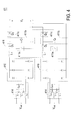
- FIG. 1 schematically illustrates the architecture of a conventional charging system.
- the conventional charging system 1 comprises an isolation unit 10 and a converting unit 11.
- the isolation unit 10 comprises a three-phase transformer Tr.
- the isolation unit 10 is included in a charging station (not shown).
- the three-phase transformer Tr is used for receiving a three-phase AC input voltage V in (e.g. a medium-high voltage level in the range between 1.2KV and 22KV) from a power-supplying terminal (e.g. a utility power source), and reducing and converting the three-phase AC input voltage V in into a three-phase AC output voltage V out (e.g. 200V ⁇ 480V).
- the converting unit 11 may be included in the charging station.
- the converting unit 11 has a two-stage circuitry configuration.
- the converting unit 11 comprises a three-phase power factor correction circuit 110 (i.e. a first-stage circuit) and a DC-DC converting circuit 111 (i.e. a second-stage circuit).
- the three-phase power factor correction circuit 110 is electrically connected with the isolation unit 10 for filtering off the harmonic wave component contained in the received current, thereby increasing the power factor. Consequently, the three-phase power factor correction circuit 110 outputs a DC transition voltage V s .
- the DC-DC converting circuit 111 is used for converting the DC transition voltage V s into a DC charging voltage V c for charging the chargeable battery in the electric vehicle in the range between 50V and 750V.
- FIG. 2 schematically illustrates the architecture of another conventional charging system.
- the first-stage circuit of the converting unit 21 of FIG. 2 comprises three sets of single-phase power factor correction circuits 210.
- the second-stage circuit of the converting unit 21 of FIG. 2 comprises three sets of DC-DC converting circuits 211.
- Each single-phase power factor correction circuit 210 is electrically connected to two different phases of the output side of the isolated transformer Tr.
- the three sets of DC-DC converting circuits 211 are electrically connected with corresponding single-phase power factor correction circuits 210, respectively.
- the output terminals of these DC-DC converting circuits 211 are connected with each other in parallel. In such way, the three-phase balance of the input current is achieved, and the chargeable battery is charged by the DC charging voltage V c .
- the three-phase transformer Tr is only configured to provide an isolating function but unable to filter off the harmonic wave
- the three-phase power factor correction circuit 110 of the charging system 1 and the single-phase power factor correction circuits 210 of the charging system 2 are necessary to filter off the harmonic wave, thereby increasing the power factor.
- the circuitry configuration of the three-phase power factor correction circuit 110 or the single-phase power factor correction circuit 210 is very complicated and the number of the electronic components thereof is very large, the charging system 1 or 2 is high.
- the real working efficiency is influenced by the conversion loss of the DC-DC converting circuit 111 or 211 and the conversion loss of the three-phase power factor correction circuit 110 or the single-phase power factor correction circuit 210. Consequently, if the three-phase AC input voltage V in is in the range between 1.2KV and 22KV, the conversion efficiency of the conventional charging system 1 or 2 may reach only 89% ⁇ 93%.
- the conventional charging system 1 or 2 is applied to the electric vehicle. Nevertheless, the conventional charging system 1 or 2 may be applied to other fields.
- the conventional charging system 1 or 2 may be applied to an internet data center with at least one sever in order to charge a chargeable battery of server.
- the conventional charging system 1 or 2 applied to the internet data center also has the above problems.
- the present invention provides a charging system for charging a chargeable battery. Since no power factor correction circuit is included in the charging system of the present invention, the harmonic wave number and the harmonic wave component are reduced, and the power factor is increased. In such way, the charging system of the present invention has reduced fabricating cost and enhanced conversion efficiency.
- a charging system for charging a chargeable battery.
- the charging system includes a phase-shifting transformer and a converting unit.
- the phase-shifting transformer includes a three-phase primary winding assembly and plural three-phase secondary winding assemblies. After a three-phase AC input voltage is received by the three-phase primary winding assembly, the three-phase AC input voltage is decreased, so that plural three-phase AC output voltages are outputted from respective three-phase secondary winding assemblies. Moreover, there is a phase-shifting angle between any two of the plural three-phase AC output voltages.
- the converting unit is electrically connected with the phase-shifting transformer, and includes plural three-phase rectifying circuits and a DC-DC converting circuit. The plural three-phase AC output voltages are rectified by the three-phase rectifying circuits, and the rectified voltage is converted into a DC charging voltage to charge the chargeable battery.
- a charging system for charging a chargeable battery.
- the charging system includes two phase-shifting transformers and two converting units.
- Each of the phase-shifting transformers includes a three-phase primary winding assembly and plural three-phase secondary winding assemblies. After a three-phase AC input voltage is received by the three-phase primary winding assembly, the three-phase AC input voltage is decreased, so that plural three-phase AC output voltages are outputted from respective three-phase secondary winding assemblies. Moreover, there is a phase-shifting angle between any two of the plural three-phase AC output voltages.
- the two converting units are electrically connected with the two phase-shifting transformers, respectively.
- Each of the converting units includes plural three-phase rectifying circuits and a DC-DC converting circuit.
- the plural three-phase AC output voltages are rectified by the three-phase rectifying circuits, and the rectified voltage is converted into a DC charging voltage, so that the chargeable battery is charged by the DC charging voltage from one of the two converting units.
- FIG. 1 schematically illustrates the architecture of a conventional charging system
- FIG. 2 schematically illustrates the architecture of another conventional charging system
- FIG. 3 schematically illustrates the architecture of another conventional charging system according to an embodiment of the present invention
- FIG. 4 schematically illustrates a variant example of the converting unit of the charging system as shown in FIG. 3 ;
- FIG. 5 schematically illustrates another variant example of the converting unit of the charging system as shown in FIG. 3 ;
- FIG. 6 schematically illustrates a further variant example of the converting unit of the charging system as shown in FIG. 3 ;
- FIG. 7 schematically illustrates the charging system of FIG. 3 applied to an internet data center
- FIG. 8 schematically illustrates the architecture of another conventional charging system according to another embodiment of the present invention.
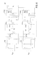
- FIG. 3 schematically illustrates the architecture of another conventional charging system according to an embodiment of the present invention.
- the charging system 3 is used for converting a three-phase AC input voltage V in into a DC charging voltage V c for charging the chargeable battery 90.
- the chargeable battery 90 is disposed within an electric vehicle 9 for providing energy required to power the electric vehicle 9.
- the three-phase AC input voltage V in is in the range between 1.2KV and 22KV and received from a power-supplying terminal (e.g. a utility power source).
- the DC charging voltage V c for charging the chargeable battery 90 is in the electric vehicle 9 in the range between 50V and 750V.
- the charging system 3 comprises an isolation unit 30 and a converting unit 31.
- the isolation unit 30 has an isolating function.
- the isolation unit 30 is included in a charging station, and comprises a phase-shifting transformer T 1 .
- the phase-shifting transformer T 1 comprises a three-phase primary winding assembly Np and plural three-phase secondary winding assemblies N s .
- the phase-shifting transformer T 1 comprises a three-phase primary winding assembly Np and four three-phase secondary winding assemblies N s .
- the three ends of the three-phase primary winding assembly N p are arranged in a delta (or ⁇ ) connection configuration for receiving the three-phase AC input voltage V in .
- the three-phase AC input voltage V in received by the three-phase primary winding assembly Np is decreased into plural three-phase AC output voltages V out , respectively.
- the phases of the four three-phase AC output voltages V out leads or lags the voltage of the three-phase primary winding assembly Np by 15 degrees, 45 degrees, 0 degree and 30 degrees, respectively.
- each three-phase secondary winding assembly N s may be arranged in a Y connection configuration, a delta connection configuration or an extended delta connection configuration.
- the phases of the four three-phase AC output voltages V out are arranged in a delta connection configuration, a Y connection configuration, an extended delta connection configuration and another extended delta connection configuration, respectively.
- each three-phase secondary winding assembly N s has at least one tapped winding structure.
- the phase-shifting transformer T 1 is a 12-pulse phase-shifting transformer.
- the phase-shifting transformer T 1 should comply with the medium-high voltage wiring safety regulations for receiving the medium-high three-phase AC input voltage V in .
- the total number of the three-phase secondary winding assemblies N s , the winding ways of the three-phase secondary winding assemblies N s and the phase-shifting angle between any two three-phase AC output voltages V out are presented herein for purpose of illustration and description only. According to the practical requirements of filtering the harmonic waves, the total number of the three-phase secondary winding assemblies N s , the winding ways of the three-phase secondary winding assemblies N s and the phase-shifting angle may be varied. For example, the phase-shifting angle may be changed by adjusting the winding size and turn number of each three-phase secondary winding assembly N s . Under this circumstance, the phase-shifting transformer T 1 is a higher-pulse phase-shifting transformer such as a 24-pulse phase-shifting transformer.
- the converting unit 31 is included in a charging station. Alternatively, in some other embodiments, the converting unit 31 is not included in a charging station.
- the converting unit 31 is electrically connected between the plural three-phase secondary winding assemblies N s of the phase-shifting transformer T 1 and the chargeable battery 90 is in the electric vehicle 9. By the converting unit 31, the plural three-phase AC output voltages V out from the plural three-phase secondary winding assemblies N s are converted into the DC charging voltage V c with the rated voltage value for charging the chargeable battery 90.
- the converting unit 31 comprises plural three-phase rectifying circuits 310 and a DC-DC converting circuit 311.
- the plural three-phase rectifying circuits 310 are electrically connected with the plural three-phase secondary winding assemblies N s , respectively.
- the plural three-phase rectifying circuits 310 the plural three-phase AC output voltages V out from the plural three-phase secondary winding assemblies N s are rectified.
- the number of the plural three-phase rectifying circuits 310 is equal to the number of the plural three-phase secondary winding assemblies N s of the phase-shifting transformer T 1 .
- the converting unit 31 has four three-phase rectifying circuits 310.
- every two three-phase rectifying circuits 310 may be connected with each other in series.
- the DC-DC converting circuit 311 is electrically connected with the plural three-phase rectifying circuits 310.
- the DC-DC converting circuit 311 the DC electric energy from the plural three-phase rectifying circuits 310 is converted into the DC charging voltage V c in three-phase balance. Consequently, the chargeable battery 90 is charged by the DC charging voltage V c .
- the DC-DC converting circuit 311 may be a multi-phase DC-DC converting circuit.
- the DC-DC converting circuit 311 is a multi-phase DC-DC converting circuit comprising a first-phase DC-DC converting circuit and a second-phase DC-DC converting circuit, which are connected with each other in parallel.
- Each of the first-phase DC-DC converting circuit and the second-phase DC-DC converting circuit is electrically connected with two serially-connected three-phase rectifying circuits 310.
- each of the first-phase DC-DC converting circuit and the second-phase DC-DC converting circuit has a non-isolated buck-type circuitry configuration.
- Each of the first-phase DC-DC converting circuit and the second-phase DC-DC converting circuit comprises a switching circuit 311 a, a diode D 1 , and an inductor L.
- the switching circuit 311 a is electrically connected between the corresponding three-phase rectifying circuit 310 and the inductor L.
- the cathode of the diode D 1 is electrically connected to the switching circuit 311a and the inductor L.
- the anode of the diode D 1 is electrically connected to a negative output terminal of the DC-DC converting circuit 311.
- the inductor L is electrically connected between the switching circuit 311a and a positive output terminal of the DC-DC converting circuit 311.
- the converting unit 31 further comprises an output filtering circuit 312 and a protecting circuit 313.
- the output filtering circuit 312 is electrically connected with an output terminal of the DC-DC converting circuit 311 for filtering the DC charging voltage V c .
- An example of the output filtering circuit 312 includes but is not limited to an output filtering capacitor C f .
- the protecting circuit 313 is also electrically connected with the output terminal of the DC-DC converting circuit 311. During the chargeable battery 90 is charged by the charging system 3, the protecting circuit 313 can prevent the voltage of the chargeable battery 90 from being returned back to the charging system 3, thereby protecting the charging system 3.
- the protecting circuit 313 comprises a diode D 2 and a fuse 313a, which are connected with each other in series.
- each of the first-phase DC-DC converting circuit and the second-phase DC-DC converting circuit of the DC-DC converting circuit 311 further comprises an input filtering circuit 314.
- the input filtering circuit 314 is electrically connected between the output terminal of a corresponding three-phase rectifying circuit 310 and the switching circuit 311 a.
- the input filtering circuit 314 comprises an input filtering inductor Lf 1 and an input filtering capacitor Cf 1 .
- the input filtering circuit 314 is configured for filtering off the electromagnetic interference (EMI).
- the converting unit 41 may further comprise plural input filtering circuits 414.
- the plural input filtering circuits 414 are connected with plural single-phase input ends of the converting unit 41.
- Each of the input filtering circuits 414 comprises plural input filtering inductors Lf 1 and plural input filtering capacitors Cf 1 .
- the plural input filtering inductors Lf 1 are connected with corresponding single-phase input ends of the converting unit 41, respectively.
- Each of the input filtering capacitors Cf 1 is connected between two corresponding single-phase input ends of the converting unit 41.
- the isolation unit 30 of the charging unit 3 comprises the phase-shifting transformer T 1 .
- the phase-shifting transformer T 1 By the phase-shifting transformer T 1 , the three-phase AC input voltage V in is converted into plural three-phase AC output voltages V out , wherein there is a phase-shifting angle between any two three-phase AC output voltages V out . That is, the power factor correction circuit included in the conventional charging system is exempted from the charging system 3 of the present invention. Consequently, the fabricating cost of the charging system 3 is reduced, and the conversion loss of the factor correction circuit is avoided. Assuming that the three-phase AC input voltage V in is in the range between 1.2KV and 22KV, the conversion efficiency of the charging system 3 may reach 96% or higher.
- the converting unit of the charging system as shown in FIG. 3 has two input terminals electrically connected with two three-phase secondary winding assemblies, and the phase-shifting transformer is not shown in the drawings.
- FIG. 4 schematically illustrates a variant example of the converting unit of the charging system as shown in FIG. 3 .
- the converting unit 41 comprises plural three-phase rectifying circuits 410 and a DC-DC converting circuit 411.
- the plural three-phase rectifying circuits 410 are electrically connected with the plural three-phase secondary winding assemblies N s , respectively (see FIG. 3 ).
- the plural three-phase rectifying circuits 410 By the plural three-phase rectifying circuits 410, the plural three-phase AC output voltages V out from the plural three-phase secondary winding assemblies N s are rectified.
- the structures and functions of the three-phase rectifying circuits 410 are similar to those of the three-phase rectifying circuits 310 of FIG. 3 , and are not redundantly described herein.
- the DC-DC converting circuit 411 may be a single-phase or multi-phase DC-DC converting circuit. As shown in FIG. 4 , the DC-DC converting circuit 411 is a multi-phase DC-DC converting circuit comprising a first-phase DC-DC converting circuit and a second-phase DC-DC converting circuit, which have similar structures and are connected with each other in parallel. Each of the first-phase DC-DC converting circuit and the second-phase DC-DC converting circuit is electrically connected a corresponding three-phase rectifying circuit 410. In addition, each of the first-phase DC-DC converting circuit and the second-phase DC-DC converting circuit has a non-isolated boost-type circuitry configuration.
- Each of the first-phase DC-DC converting circuit and the second-phase DC-DC converting circuit comprises a first inductor L 1 , a switching circuit 411a, and a diode D 1 .
- the first inductor L 1 is electrically connected between the output terminal of the three-phase rectifying circuit 410 and the anode of the diode D 1 .
- a first end of the switching circuit 411a is electrically connected to the first inductor L 1 and the anode of the diode D 1 .
- a second end of the switching circuit 411 a is electrically connected with the negative output terminal of the DC-DC converting circuit 411.
- the cathode of the diode D 1 is electrically connected with the positive output terminal of the DC-DC converting circuit 411.
- each of the first-phase DC-DC converting circuit and the second-phase DC-DC converting circuit further comprises an output filtering circuit 411 b and a protecting circuit 411 c.
- the output filtering circuit 411 b comprises an output filtering capacitor C f for filtering the DC charging voltage V c .
- the protecting circuit 411c comprises a diode D 2 . During the chargeable battery (not shown) is charged by the charging system, the protecting circuit 411c can prevent the voltage of the chargeable battery from being returned back to the charging system, thereby protecting the charging system. As previously described in FIG.
- the output filtering circuit 312 and the protecting circuit 313 of the converting unit 31 are not included in the first-phase DC-DC converting circuit and the second-phase DC-DC converting circuit.
- the output filtering circuit 411 b and the protecting circuit 411c are included in each of the first-phase DC-DC converting circuit and the second-phase DC-DC converting circuit.
- FIG. 5 schematically illustrates another variant example of the converting unit of the charging system as shown in FIG. 3 .
- the converting unit 51 comprises plural three-phase rectifying circuits 510 and a DC-DC converting circuit 511.
- the plural three-phase rectifying circuits 510 are electrically connected with the plural three-phase secondary winding assemblies N s , respectively (see FIG. 3 ).
- the plural three-phase rectifying circuits 510 By the plural three-phase rectifying circuits 510, the plural three-phase AC output voltages V out from the plural three-phase secondary winding assemblies N s are rectified.
- the structures and functions of the three-phase rectifying circuits 510 are similar to those of the three-phase rectifying circuits 310 of FIG. 3 , and are not redundantly described herein.
- the DC-DC converting circuit 511 is a multi-phase DC-DC converting circuit comprising a first-phase DC-DC converting circuit and a second-phase DC-DC converting circuit, which have similar structures and are connected with each other in parallel.
- Each of the first-phase DC-DC converting circuit and the second-phase DC-DC converting circuit is electrically connected a corresponding three-phase rectifying circuit 510.
- each of the first-phase DC-DC converting circuit and the second-phase DC-DC converting circuit has an isolated full-bridge circuitry configuration.
- Each of the first-phase DC-DC converting circuit and the second-phase DC-DC converting circuit comprises a full-bridge switching circuit 511 a, a transformer 511b, and an output rectifying circuit 511c.
- the full-bridge switching circuit 511a is electrically connected with the output terminal of the three-phase rectifying circuit 510 and electrically connected with the primary side of the transformer 511b.
- the output rectifying circuit 511c is electrically connected with the secondary side of the transformer 511b. By the output rectifying circuit 511c, the electric energy outputted from the secondary side of the transformer 511b is rectified into the DC charging voltage V c .
- each of the first-phase DC-DC converting circuit and the second-phase DC-DC converting circuit further comprises an output filtering circuit 511d and a protecting circuit 511e.
- the output filtering circuit 511d comprises an output filtering capacitor C f and an output filtering inductor L f .
- the protecting circuit 511e comprises a diode D 2 .
- the functions of the output filtering circuit 511d and the protecting circuit 511e are similar to those of the output filtering circuit 411b and the protecting circuit 411c of FIG. 4 , and are not redundantly described herein.
- FIG. 6 schematically illustrates a further variant example of the converting unit of the charging system as shown in FIG. 3 .
- the converting unit 61 comprises plural three-phase rectifying circuits 510 and a DC-DC converting circuit 511.
- the DC-DC converting circuit 511 is a multi-phase DC-DC converting circuit comprising a first-phase DC-DC converting circuit and a second-phase DC-DC converting circuit, which have similar structures and are connected with each other in parallel.
- each of the first-phase DC-DC converting circuit and the second-phase DC-DC converting circuit further comprises a resonant circuit 611.
- the resonant circuit 611 is electrically connected with the primary side of the transformer 511b.
- the resonant circuit 611 comprises a resonant capacitor C r and a resonant inductor L r . Due to the resonant circuit 611, each of the first-phase DC-DC converting circuit and the second-phase DC-DC converting circuit has an isolated resonant circuitry configuration.
- the output filtering circuit 511d comprises the output filtering capacitor C f and the output filtering inductor L f . Whereas, as shown in FIG. 6 , the output filtering circuit 511d only comprises the output filtering capacitor C f .
- the charging system 3 is used for charging the chargeable battery 90 in the electric vehicle 9.
- the charging system 3 may be used for charging at least one chargeable battery 80 of an internet data center 8.
- the internet data center 8 further comprises at least one server 81.
- the server 81 is connected with the output terminal of the charging system 3.
- the chargeable battery 80 is used for providing electric energy required to power the server 81.
- the DC charging voltage V c from the charging system 3 may charge the chargeable battery 80 through the server 81.
- the chargeable battery 80 and the server 81 are separately disposed within the internet data center 8.
- the chargeable battery 80 may be directly installed in the server 81.
- the number of the chargeable batteries 80 is equal to the number of the servers 81.
- one chargeable battery 80 is disposed within the internet data center 8.
- plural chargeable batteries 80 are disposed within the internet data center 8.
- the plural servers 81 are connected with the plural chargeable batteries 80 one by one.
- the plural chargeable batteries 80 are charged by respective chargeable batteries 80 through respective servers 81.
- FIG. 8 schematically illustrates the architecture of another conventional charging system according to another embodiment of the present invention.
- the charging system 3 comprises two isolation units 30 and two converting units 31.
- Each of the two isolation units 30 comprises a phase-shifting transformer T 1 .
- These two phase-shifting transformers T 1 of two isolation units 30 are respectively used for two medium-high three-phase AC input voltages V in and V in1 from two power-supplying terminals.
- the two power-supplying terminals are provided by an identical utility power source or two different utility power sources.
- the output terminal of the isolation unit 30 is connected with a corresponding converting unit 31.
- the output terminals of the two converting units 31 may be connected with each other in parallel.
- the converting unit 31 may be a single-phase or multi-phase converting unit.
- the converting unit 31 is a multi-phase converting unit.
- each of the converting units 31 comprises plural three-phase rectifying circuits 310 and a DC-DC converting circuit 311.
- the internal circuitry configurations and the operating principles of the isolation unit 30 and the converting unit 31 are similar to those of FIG. 3 or FIG. 7 , and are not redundantly described herein.
- one of the isolation units 30 and the corresponding converting unit 31 are defined as a main power-supplying unit for providing the DC charging voltage V c .
- the other isolation unit 30 and the corresponding converting unit 31 are defined as a redundant power-supplying unit.
- the three-phase AC input voltage V in is normally received by the main power-supplying unit, the three-phase AC input voltage V in is converted into the DC charging voltage V c by the main power-supplying unit.
- the redundant power-supplying unit is disabled or in a standby state.
- the converting unit 31 of the main power-supplying unit is disabled under control of the controlling unit of the charging system 3.
- the redundant power-supplying unit is enabled to convert the three-phase AC input voltage V in1 into the DC charging voltage V c .
- the charging system 3 of FIG. 8 further comprises an output filtering circuit 312 and a protecting circuit 313, which are connected to the output terminal of the charging system 3.
- the charging system 3 of FIG. 8 further comprises an output filtering circuit 411b and a protecting circuit 411c, which are included in each converting unit 31.
- the isolation unit of the charging system is implemented by a phase-shifting transformer.
- the phase-shifting transformer is used for converting a medium-high three-phase AC input voltage into plural three-phase AC output voltages, wherein there is a phase-shifting angle between any two three-phase AC output voltages. Since no power factor correction circuit is included in the charging system of the present invention, the harmonic wave number and the harmonic wave component are reduced, and the power factor is increased. In such way, the charging system of the present invention has reduced fabricating cost and enhanced conversion efficiency.
Landscapes
- Engineering & Computer Science (AREA)
- Power Engineering (AREA)
- Transportation (AREA)
- Mechanical Engineering (AREA)
- Charge And Discharge Circuits For Batteries Or The Like (AREA)
- Secondary Cells (AREA)
Applications Claiming Priority (1)
| Application Number | Priority Date | Filing Date | Title |
|---|---|---|---|
| TW101117510A TWI535168B (zh) | 2012-05-17 | 2012-05-17 | 充電系統 |
Publications (2)
| Publication Number | Publication Date |
|---|---|
| EP2665152A2 true EP2665152A2 (de) | 2013-11-20 |
| EP2665152A3 EP2665152A3 (de) | 2016-02-17 |
Family
ID=47665972
Family Applications (1)
| Application Number | Title | Priority Date | Filing Date |
|---|---|---|---|
| EP13153647.6A Withdrawn EP2665152A3 (de) | 2012-05-17 | 2013-02-01 | Ladesystem |
Country Status (4)
| Country | Link |
|---|---|
| US (1) | US9236755B2 (de) |
| EP (1) | EP2665152A3 (de) |
| JP (1) | JP2013243114A (de) |
| TW (1) | TWI535168B (de) |
Cited By (8)
| Publication number | Priority date | Publication date | Assignee | Title |
|---|---|---|---|---|
| CN109104095A (zh) * | 2018-10-25 | 2018-12-28 | 合肥工业大学 | 三端口变换器半开关周期采样的预测电流移相控制方法 |
| EP3428000A1 (de) * | 2017-07-12 | 2019-01-16 | Dr. Ing. h.c. F. Porsche AG | Vorrichtung zum laden mindestens einer batterie |
| EP3501884A1 (de) * | 2017-12-19 | 2019-06-26 | Dr. Ing. h.c. F. Porsche AG | Transformatorvorrichtung für eine ladestation für das elektrische laden von fahrzeugen mit wenigstens zwei ladepunkten |
| GB2578362A (en) * | 2018-08-29 | 2020-05-06 | Hamilton Sundstrand Corp | Direct current voltage regulation of permanent magnet generator |
| GB2578813A (en) * | 2018-09-10 | 2020-05-27 | Hamilton Sundstrand Corp | Direct current voltage regulation of permanent magnet generator |
| US10855216B2 (en) | 2018-09-10 | 2020-12-01 | Hamilton Sundstrand Corporation | Voltage regulation of multi-phase permanent magnet generator |
| EP3817181A1 (de) * | 2019-10-30 | 2021-05-05 | Delta Electronics (Shanghai) Co., Ltd. | Gleichstromversorgungssystem |
| US11431190B2 (en) | 2019-10-30 | 2022-08-30 | Delta Electronics (Shanghai) Co., Ltd | DC power supply system and method |
Families Citing this family (21)
| Publication number | Priority date | Publication date | Assignee | Title |
|---|---|---|---|---|
| DE102015110023A1 (de) * | 2015-06-23 | 2016-12-29 | Dr. Ing. H.C. F. Porsche Aktiengesellschaft | Ladestation und Verfahren zum Laden eines Plug-In-Kraftfahrzeuges an einer Ladesäule |
| DE102016102053A1 (de) | 2016-02-05 | 2017-08-10 | Dr. Ing. H.C. F. Porsche Aktiengesellschaft | Schaltungssystem für eine Ladestation, Ladestation und Verwenden einer Ladestation |
| DE102016103011A1 (de) | 2016-02-22 | 2017-08-24 | Dr. Ing. H.C. F. Porsche Aktiengesellschaft | Verfahren und Vorrichtung zum Betrieb von Ladestationen |
| KR101849626B1 (ko) | 2016-03-03 | 2018-04-17 | 계명대학교 산학협력단 | 고효율 전기자동차 충전기 |
| CN107294145A (zh) * | 2016-03-30 | 2017-10-24 | 通用电气公司 | 充电装置、系统和方法 |
| US9831846B2 (en) * | 2016-04-19 | 2017-11-28 | Rockwell Automation Technologies, Inc. | Power conversion system |
| US11159091B2 (en) * | 2016-05-17 | 2021-10-26 | Georgia Tech Research Corporation | Stackable isolated voltage optimization module |
| DE102016123924A1 (de) | 2016-12-09 | 2018-06-14 | Dr. Ing. H.C. F. Porsche Aktiengesellschaft | Modulare Leistungselektronik zum Laden eines elektrisch betriebenen Fahrzeugs |
| DE102017107355B4 (de) * | 2017-04-05 | 2021-11-11 | Semikron Elektronik Gmbh & Co. Kg | Stromrichteranordnung zur Speisung von Fahrzeugen und Anlage hiermit |
| EP3442089B1 (de) | 2017-08-11 | 2020-06-17 | HELLA GmbH & Co. KGaA | Steuerschaltung für duale aktive brücken zur verwendung mit unsymmetrischen netzspannungen |
| DE102017127380A1 (de) * | 2017-11-21 | 2019-05-23 | Innogy Se | Ladestation für Elektrofahrzeuge |
| DE102017128092B3 (de) | 2017-11-28 | 2019-02-21 | Dr. Ing. H.C. F. Porsche Aktiengesellschaft | Verfahren und System zum Bereitstellen eines Ladeparks mit einer Mehrzahl von Ladepunkten |
| CN108923409B (zh) | 2018-08-20 | 2021-07-02 | 台达电子工业股份有限公司 | 直流供电系统 |
| TWI693780B (zh) * | 2019-06-03 | 2020-05-11 | 緯穎科技服務股份有限公司 | 用於電源供應系統之控制方法及電源供應系統 |
| US11404966B2 (en) * | 2020-07-02 | 2022-08-02 | Delta Electronics, Inc. | Isolated multi-phase DC/DC converter with reduced quantity of blocking capacitors |
| US20230408595A1 (en) * | 2020-11-27 | 2023-12-21 | Semiconductor Energy Laboratory Co., Ltd. | Power storage system, vehicle, and electronic device |
| KR102282679B1 (ko) * | 2021-02-03 | 2021-07-28 | (주)그린파워 | 다이렉트 전기차 충전기 |
| CA3159480A1 (en) | 2021-05-19 | 2022-11-19 | Marco Tremblay | Power supply unit for vehicle charging |
| CN113675848A (zh) * | 2021-09-14 | 2021-11-19 | 中冶赛迪工程技术股份有限公司 | 一种供电控制器件、装置及方法 |
| CN114553047B (zh) * | 2022-01-21 | 2024-09-27 | 东北电力大学 | 基于三相变压器级联的三相交流变直流变换器 |
| WO2026016355A1 (zh) * | 2024-07-19 | 2026-01-22 | 台达电子工业股份有限公司 | 单级式交直流谐振转换器 |
Family Cites Families (37)
| Publication number | Priority date | Publication date | Assignee | Title |
|---|---|---|---|---|
| US3784892A (en) * | 1971-05-20 | 1974-01-08 | Gen Syst Inc | Battery charging system for emergency battery systems |
| US4152640A (en) * | 1977-09-23 | 1979-05-01 | Westinghouse Electric Corp. | Two phase high voltage insulation testing of multiphase windings |
| JP2624790B2 (ja) | 1988-07-29 | 1997-06-25 | 株式会社日立製作所 | 可変直流電源装置 |
| US5214385A (en) * | 1991-05-22 | 1993-05-25 | Commonwealth Edison Company | Apparatus and method for utilizing polarization voltage to determine charge state of a battery |
| US5499178A (en) * | 1991-12-16 | 1996-03-12 | Regents Of The University Of Minnesota | System for reducing harmonics by harmonic current injection |
| US5986907A (en) * | 1996-06-21 | 1999-11-16 | Limpaecher; Rudolf | Method and apparatus for rectification derectification and power flow control |
| US6278279B1 (en) * | 1998-08-28 | 2001-08-21 | International Business Machines Corporation | Path test for a DC battery back-up system |
| US6633154B1 (en) * | 2000-01-04 | 2003-10-14 | William B. Duff, Jr. | Method and circuit for using polarized device in AC applications |
| CA2369060C (en) * | 2001-01-24 | 2005-10-04 | Nissin Electric Co., Ltd. | Dc-dc-converter and bi-directional dc-dc converter and method of controlling the same |
| US6650557B2 (en) * | 2001-04-27 | 2003-11-18 | Honeywell International Inc. | 18-pulse rectification system using a wye-connected autotransformer |
| US6528972B2 (en) * | 2001-07-20 | 2003-03-04 | Tai-Her Yang | Voltage detection controlled shunt and voltage division circuit for a charging device |
| US6559562B1 (en) * | 2001-12-14 | 2003-05-06 | Ssi Power, Llc | Voltage sag and over-voltage compensation device with pulse width modulated autotransformer |
| US20060017328A1 (en) * | 2003-02-10 | 2006-01-26 | Bryde Jan H | Control system for distributed power generation, conversion, and storage system |
| US7135836B2 (en) * | 2003-03-28 | 2006-11-14 | Power Designers, Llc | Modular and reconfigurable rapid battery charger |
| US6950322B2 (en) * | 2003-04-10 | 2005-09-27 | Rsm Electron Power, Inc. | Regulated AC to DC converter for aerospace applications |
| US20120181973A1 (en) * | 2003-08-29 | 2012-07-19 | Robert Lyden | Solar array resembling natural foliage including means for wireless transmission of electric power |
| US6954366B2 (en) * | 2003-11-25 | 2005-10-11 | Electric Power Research Institute | Multifunction hybrid intelligent universal transformer |
| CN1270438C (zh) * | 2004-08-20 | 2006-08-16 | 清华大学 | 3kv~10kv中高压多电平三相交流电动机变频驱动装置 |
| US7375996B2 (en) * | 2005-09-09 | 2008-05-20 | Indian Institute Of Technology, Delhi-Department Of Electrical Engineering | Reduced rating T-connected autotransformer for converting three phase AC voltages to nine/six phase shifted AC voltages |
| US20080039979A1 (en) * | 2006-08-10 | 2008-02-14 | V2 Green Inc. | Smart Islanding and Power Backup in a Power Aggregation System for Distributed Electric Resources |
| JP5325378B2 (ja) | 2006-09-05 | 2013-10-23 | 新明和工業株式会社 | 電源システムの高調波低減装置 |
| US7948340B2 (en) * | 2007-08-29 | 2011-05-24 | Siemens Industry, Inc. | Three-phase multi-winding device |
| EP2281333A2 (de) * | 2008-04-09 | 2011-02-09 | Intellon Corporation | Übertragungsleitungs-richtungsbewusstheit |
| US8261102B2 (en) | 2008-04-28 | 2012-09-04 | Delta Electronics, Inc. | Power management system capable of saving power and optimizing operating efficiency of power supplies for providing power with back-up or redundancy to plural loads |
| TW200950248A (en) | 2008-05-27 | 2009-12-01 | Zippy Tech Corp | Power supply equipped with system switching circuit |
| US7852605B2 (en) * | 2008-06-20 | 2010-12-14 | Georgia-Pacific Consumer Products Lp | Arc-flash hazard protection system for three-phase electrical distribution system |
| WO2010091260A2 (en) * | 2009-02-06 | 2010-08-12 | Abb Research Ltd. | A hybrid distribution transformer with ac & dc power capabilities |
| CN101989816A (zh) * | 2009-07-31 | 2011-03-23 | 西门子(中国)有限公司 | 一种高压变频装置 |
| US8030884B2 (en) * | 2009-08-31 | 2011-10-04 | General Electric Company | Apparatus for transferring energy using onboard power electronics and method of manufacturing same |
| US8118147B2 (en) * | 2009-09-11 | 2012-02-21 | Better Place GmbH | Cable dispensing system |
| TWI388116B (zh) | 2009-11-26 | 2013-03-01 | Chung Ming Young | Method and device for active phase-to-phase transformer used in twenty-four pulse wave AC / DC converter |
| KR101611296B1 (ko) * | 2010-02-09 | 2016-04-12 | 엘지전자 주식회사 | 스마트 디바이스를 이용한 전력 제어 방법 및 장치 |
| ES2777887T3 (es) * | 2010-05-03 | 2020-08-06 | Siemens Gamesa Renewable Energy As | Sistema para intercambiar energía eléctrica entre una batería y una red eléctrica y procedimiento respectivo |
| US8384244B2 (en) * | 2010-06-09 | 2013-02-26 | Microsoft Corporation | Rack-based uninterruptible power supply |
| CN102891613A (zh) * | 2011-07-21 | 2013-01-23 | 台达电子企业管理(上海)有限公司 | 一种ac-dc 电源转换器及其dc 充电站 |
| US9197065B2 (en) * | 2011-12-06 | 2015-11-24 | Varentec, Inc. | Compact dynamic phase angle regulators |
| US9148068B2 (en) * | 2011-12-19 | 2015-09-29 | Facebook, Inc. | Backup power system for rack-mounted equipment |
-
2012
- 2012-05-17 TW TW101117510A patent/TWI535168B/zh active
- 2012-09-11 US US13/610,596 patent/US9236755B2/en active Active
-
2013
- 2013-02-01 EP EP13153647.6A patent/EP2665152A3/de not_active Withdrawn
- 2013-02-27 JP JP2013037695A patent/JP2013243114A/ja active Pending
Non-Patent Citations (1)
| Title |
|---|
| None |
Cited By (15)
| Publication number | Priority date | Publication date | Assignee | Title |
|---|---|---|---|---|
| US11214155B2 (en) | 2017-07-12 | 2022-01-04 | Dr. Ing. H.C. F. Porsche Aktiengesellschaft | Device for charging at least one battery |
| EP3428000A1 (de) * | 2017-07-12 | 2019-01-16 | Dr. Ing. h.c. F. Porsche AG | Vorrichtung zum laden mindestens einer batterie |
| EP3501884A1 (de) * | 2017-12-19 | 2019-06-26 | Dr. Ing. h.c. F. Porsche AG | Transformatorvorrichtung für eine ladestation für das elektrische laden von fahrzeugen mit wenigstens zwei ladepunkten |
| US10696183B2 (en) | 2017-12-19 | 2020-06-30 | Dr. Ing. H.C. F. Porsche Aktiengesellschaft | Transformer apparatus for a charging station for electrically charging vehicles and having at least two charging points |
| GB2578362A (en) * | 2018-08-29 | 2020-05-06 | Hamilton Sundstrand Corp | Direct current voltage regulation of permanent magnet generator |
| GB2578362B (en) * | 2018-08-29 | 2022-10-05 | Hamilton Sundstrand Corp | Direct current voltage regulation of permanent magnet generator |
| GB2578813A (en) * | 2018-09-10 | 2020-05-27 | Hamilton Sundstrand Corp | Direct current voltage regulation of permanent magnet generator |
| US10778127B2 (en) | 2018-09-10 | 2020-09-15 | Hamilton Sundstrand Corporation | Direct current voltage regulation of permanent magnet generator |
| US10855216B2 (en) | 2018-09-10 | 2020-12-01 | Hamilton Sundstrand Corporation | Voltage regulation of multi-phase permanent magnet generator |
| GB2578813B (en) * | 2018-09-10 | 2022-04-13 | Hamilton Sundstrand Corp | Direct current voltage regulation of permanent magnet generator |
| CN109104095B (zh) * | 2018-10-25 | 2020-09-04 | 合肥工业大学 | 三端口变换器半开关周期采样的预测电流移相控制方法 |
| CN109104095A (zh) * | 2018-10-25 | 2018-12-28 | 合肥工业大学 | 三端口变换器半开关周期采样的预测电流移相控制方法 |
| US11205897B2 (en) | 2019-10-30 | 2021-12-21 | Delta Electronics (Shanghai) Co., Ltd | DC power supply system |
| EP3817181A1 (de) * | 2019-10-30 | 2021-05-05 | Delta Electronics (Shanghai) Co., Ltd. | Gleichstromversorgungssystem |
| US11431190B2 (en) | 2019-10-30 | 2022-08-30 | Delta Electronics (Shanghai) Co., Ltd | DC power supply system and method |
Also Published As
| Publication number | Publication date |
|---|---|
| JP2013243114A (ja) | 2013-12-05 |
| EP2665152A3 (de) | 2016-02-17 |
| US9236755B2 (en) | 2016-01-12 |
| TWI535168B (zh) | 2016-05-21 |
| US20130307486A1 (en) | 2013-11-21 |
| TW201349721A (zh) | 2013-12-01 |
Similar Documents
| Publication | Publication Date | Title |
|---|---|---|
| US9236755B2 (en) | Charging system for reducing harmonic wave and fabricating cost | |
| US11296533B2 (en) | Vehicle power supply device | |
| US8957542B2 (en) | Non-isolated AC-DC converter having a positive output buck-boost converter and PFC at input supply | |
| US10654371B2 (en) | Charging apparatus for electric vehicle | |
| CN112350588B (zh) | 应用于固态变压器架构的电源装置及三相电源系统 | |
| US9088221B2 (en) | High-voltage power supply module and power supply system | |
| US8482249B2 (en) | Charging apparatus with alternating current- and direct current-charging functions for mobile vehicle | |
| CN115362610B (zh) | 具有多个lvdc输出的sst系统 | |
| AU2001284979A1 (en) | High efficiency fuel cell power conditioner | |
| EP3399634B1 (de) | Isolierter bidirektionaler gleichspannungswandler | |
| US9246399B2 (en) | Power supply system and control method thereof | |
| US11811300B2 (en) | Isolated converter | |
| US20240356333A1 (en) | Power converter system with multiple isolated dc load ports | |
| CN103427463A (zh) | 充电系统 | |
| US11440423B2 (en) | System and method for on-board charger with a pulsating buffer | |
| US20240128008A1 (en) | Transformer of an electrical system for dc voltage conversion and for charging of batteries of a vehicle | |
| Vinusha et al. | Improved power quality of single phase on-board charger with wide voltage conversion range | |
| Singh et al. | State-of-the-art Charging Solutions for Electric Transportation and Autonomous E-mobility. | |
| Kanakri et al. | Capacitorless notch resonant converters for miniaturized llclc resonant converters in electric vehicle charging applications | |
| US20250167585A1 (en) | Dc backup power system | |
| TWI895062B (zh) | 多埠雙向轉換器 | |
| Wang et al. | High-power WPT systems: Step-up transformer vs. partial-series tuning | |
| EP4287482A1 (de) | Leistungswandlertopologie | |
| US20250202381A1 (en) | Power supply system | |
| EP4482007A1 (de) | Leistungsumwandlungsvorrichtung und steuerungsverfahren dafür sowie elektrofahrzeugladesystem |
Legal Events
| Date | Code | Title | Description |
|---|---|---|---|
| PUAI | Public reference made under article 153(3) epc to a published international application that has entered the european phase |
Free format text: ORIGINAL CODE: 0009012 |
|
| 17P | Request for examination filed |
Effective date: 20130201 |
|
| AK | Designated contracting states |
Kind code of ref document: A2 Designated state(s): AL AT BE BG CH CY CZ DE DK EE ES FI FR GB GR HR HU IE IS IT LI LT LU LV MC MK MT NL NO PL PT RO RS SE SI SK SM TR |
|
| AX | Request for extension of the european patent |
Extension state: BA ME |
|
| PUAL | Search report despatched |
Free format text: ORIGINAL CODE: 0009013 |
|
| AK | Designated contracting states |
Kind code of ref document: A3 Designated state(s): AL AT BE BG CH CY CZ DE DK EE ES FI FR GB GR HR HU IE IS IT LI LT LU LV MC MK MT NL NO PL PT RO RS SE SI SK SM TR |
|
| AX | Request for extension of the european patent |
Extension state: BA ME |
|
| RIC1 | Information provided on ipc code assigned before grant |
Ipc: H02M 1/00 20060101ALN20160112BHEP Ipc: H02J 7/00 20060101ALN20160112BHEP Ipc: H02J 7/02 20060101AFI20160112BHEP |
|
| STAA | Information on the status of an ep patent application or granted ep patent |
Free format text: STATUS: THE APPLICATION IS DEEMED TO BE WITHDRAWN |
|
| 18D | Application deemed to be withdrawn |
Effective date: 20160818 |