EP2665332A1 - Dispositif utilisateur et procédé de mesure - Google Patents
Dispositif utilisateur et procédé de mesure Download PDFInfo
- Publication number
- EP2665332A1 EP2665332A1 EP12734020.6A EP12734020A EP2665332A1 EP 2665332 A1 EP2665332 A1 EP 2665332A1 EP 12734020 A EP12734020 A EP 12734020A EP 2665332 A1 EP2665332 A1 EP 2665332A1
- Authority
- EP
- European Patent Office
- Prior art keywords
- rssi
- sub
- frame
- measurement
- rsrq
- Prior art date
- Legal status (The legal status is an assumption and is not a legal conclusion. Google has not performed a legal analysis and makes no representation as to the accuracy of the status listed.)
- Withdrawn
Links
Images





Classifications
-
- H—ELECTRICITY
- H04—ELECTRIC COMMUNICATION TECHNIQUE
- H04W—WIRELESS COMMUNICATION NETWORKS
- H04W24/00—Supervisory, monitoring or testing arrangements
- H04W24/10—Scheduling measurement reports ; Arrangements for measurement reports
-
- H—ELECTRICITY
- H04—ELECTRIC COMMUNICATION TECHNIQUE
- H04B—TRANSMISSION
- H04B17/00—Monitoring; Testing
- H04B17/30—Monitoring; Testing of propagation channels
- H04B17/309—Measuring or estimating channel quality parameters
- H04B17/318—Received signal strength
- H04B17/328—Reference signal received power [RSRP]; Reference signal received quality [RSRQ]
-
- H—ELECTRICITY
- H04—ELECTRIC COMMUNICATION TECHNIQUE
- H04J—MULTIPLEX COMMUNICATION
- H04J11/00—Orthogonal multiplex systems, e.g. using WALSH codes
- H04J11/0023—Interference mitigation or co-ordination
- H04J11/005—Interference mitigation or co-ordination of intercell interference
-
- H—ELECTRICITY
- H04—ELECTRIC COMMUNICATION TECHNIQUE
- H04L—TRANSMISSION OF DIGITAL INFORMATION, e.g. TELEGRAPHIC COMMUNICATION
- H04L5/00—Arrangements affording multiple use of the transmission path
- H04L5/003—Arrangements for allocating sub-channels of the transmission path
- H04L5/0048—Allocation of pilot signals, i.e. of signals known to the receiver
-
- H—ELECTRICITY
- H04—ELECTRIC COMMUNICATION TECHNIQUE
- H04L—TRANSMISSION OF DIGITAL INFORMATION, e.g. TELEGRAPHIC COMMUNICATION
- H04L5/00—Arrangements affording multiple use of the transmission path
- H04L5/003—Arrangements for allocating sub-channels of the transmission path
- H04L5/0053—Allocation of signalling, i.e. of overhead other than pilot signals
-
- H—ELECTRICITY
- H04—ELECTRIC COMMUNICATION TECHNIQUE
- H04L—TRANSMISSION OF DIGITAL INFORMATION, e.g. TELEGRAPHIC COMMUNICATION
- H04L5/00—Arrangements affording multiple use of the transmission path
- H04L5/003—Arrangements for allocating sub-channels of the transmission path
- H04L5/0058—Allocation criteria
- H04L5/0073—Allocation arrangements that take into account other cell interferences
-
- H—ELECTRICITY
- H04—ELECTRIC COMMUNICATION TECHNIQUE
- H04W—WIRELESS COMMUNICATION NETWORKS
- H04W36/00—Hand-off or reselection arrangements
- H04W36/0005—Control or signalling for completing the hand-off
- H04W36/0083—Determination of parameters used for hand-off, e.g. generation or modification of neighbour cell lists
- H04W36/0085—Hand-off measurements
- H04W36/0094—Definition of hand-off measurement parameters
-
- H—ELECTRICITY
- H04—ELECTRIC COMMUNICATION TECHNIQUE
- H04B—TRANSMISSION
- H04B17/00—Monitoring; Testing
- H04B17/30—Monitoring; Testing of propagation channels
- H04B17/382—Monitoring; Testing of propagation channels for resource allocation, admission control or handover
Definitions
- the present invention relates to a user equipment and a measurement method.
- a user equipment moves from one cell to another, the user equipment switches to the other cell to continue communications.
- the switching to the other cell is referred to as "handover".
- the user equipment when the user equipment moves to a neighboring cell from a serving cell and signal strength in the neighboring cell is higher than signal strength in the serving cell (cell in which the user equipment originally performs communications), the user equipment performs the handover to the neighboring cell.
- the user equipment performs the handover according to procedures illustrated in Fig. 1 .
- the user equipment measures signal power of the neighboring cell. Then, the user equipment confirms whether or not the signal power of the neighboring cell satisfies the following Expression 1.
- the offset is a value provided so that the handover does not frequently occur from the serving cell to the neighboring cell at a cell boundary.
- the offset may be either a positive value or a negative value.
- the positive value is used as the offset value provided such that the handover does not frequently occur.
- Event A3 is defined as any other event, that is, the invent other than the "Event A3”.
- a signal power in the above-described example maybe "Reference Signal Received Power (RSRP)" which is a received power of a reference signal.
- RSRP Reference Signal Received Power
- the RSRP is defined in Non-Patent Literature 1. Further, the above-described LTE may be referred to as "E-UTRA/E-UTRAN” . In addition, the reference signal may be a common reference signal, more specifically.
- the handover is performed based on the RSRP of the serving cell and the RSRP of the neighboring cell.
- a "Reference Signal Received Quality (RSRQ) may be used instead of the RSRP.
- the RSRQ represents a value expressed as the RSRP divided by a Received Signal Strength Indicator (RSSI) and is defined in Non-Patent Literature 1. That is, the RSRQ is calculated by the following Expression 2.
- RSRQ RSRP / RSSI
- the RSSI represents the sum of the received powers, that is, a total received power, of all signals such as a desired signal from the serving cell, an interference signal from the neighboring cell, a noise signal due to a thermal noise, or the like and is defined in Non-Patent Literature 1.
- the RSSI may be referred to as "E-UTRA carrier RSSI”.
- the value of the above-described RSSI differs in different frequency carriers.
- the value of RSSI is large in the frequency carrier of high congestion degree, while the value of RSSI is small in the frequency carrier of low congestion degree.
- the values of RSRQ may sometimes be different by different values of RSSI due to the congestion degree or the like even though the values of RSRP are the same. Therefore, the RSRQ is used at the time of performing the handover of different frequencies, for example.
- RSRP radio quality
- RSRQ Radio quality
- the radio quality used in the above-described handover has a large effect on the communication quality of the mobile communication system.
- measurement accuracy in S1 is related to the quality of handover.
- the handover is not performed in an area where the handover should actually be performed and the communication is disconnected.
- the handover is performed in an area where the handover should actually not be performed and the communication is disconnected.
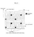
- the RSSI used for calculating the above-described RSRQ is measured in only the OFDM symbols containing the reference signal, as illustrated in Fig. 2 .
- the OFDM symbols #0/#4/#7/#11 are the OFDM symbols containing the reference signal, and other OFDM symbols are the OFDM symbols not containing the reference signal.
- the reference signal is a reference signal of an antenna port 0, when a plurality of transmission antennas is present.
- e-ICIC Enhanced Inter Cell Interference Coordination
- the e-ICIC technique being a technique for improving throughput by suppressing the interference from the neighboring cell.
- the user equipment performs the measurement of the above-described RSRP and RSRQ on a specific sub-frame.
- the neighboring cell which is an interfering cell, does not transmit a signal of downlink to sub-frames #2/#3/#6/#7, for example.
- the user equipment for performing the communication using the serving cell to be interfered performs the measurement of the RSRP and the RSRQ on only the sub-frames #2/#3/#6/#7 to which the signal of downlink is not transmitted.
- the interference is present by performing the measurement of the RSRP and the RSRQ, and it is possible to perform the measurement of the RSRP and the RSRQ in which the influence of interference is excluded at the time of performing interference coordination by the e-ICIC.
- the user equipment is notified that to which sub-frame the signal of downlink from the neighboring cell is not transmitted, that is, on which sub-frame the user equipment performs the measurement of the RSRP and the RSRQ.
- Non-Patent Literature 1 3GPP TS36. 214 v10.0.0, December, 2010
- the measurement of RSRP and RSRQ at the time of performing an e-ICIC is performed on specific sub-frames, that is, sub-frames in which interference from a neighboring cell is not present.
- the specific sub-frames are notified to the user equipment from the network.
- the RSSI which is a denominator at the time of calculating the RSRQ is measured in only OFDM symbols containing a reference signal, as illustrated in Fig. 2 .
- the above-described value of RSSI certainly contains a power of the reference signal of the neighboring cell, as illustrated in Fig. 4 .
- the neighboring cell transmits only the reference signal and the serving cell transmits both of the reference signal and a data signal and that the signal from the neighboring cell is ten times greater than that from the serving cell.
- RSRQ the value of RSRQ is calculated as follows.
- the RSRQ in which the signal from the neighboring cell is excluded is calculated as follows.
- RSRQ 1/12.
- "1/12” is “-10.8 dB” when is converted into dB value.
- RSRQ a value of RSRQ
- the present invention has been achieved in view of the above-described problems, and an object thereof is to provide the user equipment and the measurement method, which are capable of measuring radio quality with good accuracy.
- a first characteristic of the present invention is a user equipment configured to measure a radio quality of a serving cell and a neighboring cell, the equipment comprising: a measuring unit that is configured, with regard to a predetermined sub-frame, to measure the radio quality for all time symbols within the predetermined sub-frame and with regard to sub-frames other than the predetermined sub-frame, to measure the radio quality for time symbols containing a reference signal within the sub-frames.
- a second characteristic of the present invention is a user equipment configured to measure a radio quality of a serving cell and a neighboring cell, the equipment comprising: a measuring unit that is configured, with regard to a predetermined sub-frame, to measure the radio quality for time symbols not containing a reference signal within the predetermined sub-frame and with regard to sub-frames other than the predetermined sub-frame, to measure the radio quality for time symbols containing the reference signal within the sub-frames.
- a third characteristic of the present embodiment is a user equipment configured to measure a radio quality of a serving cell and a neighboring cell, the equipment comprising: a measuring unit that is configured to measure the radio quality when the radio quality is calculated from a received power of a reference signal of the serving cell and the neighboring cell and a total of received powers within a band, wherein the measuring unit calculates the total of received powers within the band such that the received power of the reference signal of the neighboring cell is not included in the total of received powers within the band.
- a fourth characteristic of the present invention is a measurement method of measuring a radio quality of a serving cell and a neighboring cell, the method comprising: step A of determining time symbols for measuring the radio quality; and step B of measuring the radio quality for the determined time symbols, wherein the time symbols are determined depending on whether or not interference coordination is applied in the step B.
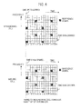
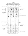
- Figs. 5 and 6 are diagram illustrating a measurement interval of RSSI in the mobile communication system according to the present embodiment, respectively.
- RSSI of all OFDM symbols within one sub-frame is measured, as illustrated in Fig. 5
- RSSI of OFDM symbols containing a reference signal within one sub-frame is measured, as illustrated in Fig. 6 .
- the RSRI of OFDM symbols #0 to #13 is measured, as illustrated in Fig. 5
- the RSSI of OFDM symbols #0/#4/#7/#11 is measured, as illustrated in Fig. 6 .
- the RSSI of all OFDM symbols within one sub-frame is measured in the designated sub-frame, as illustrated in Fig. 5 .
- the RSSI of the OFDM symbols containing the reference signal within one sub-frame is measured, as illustrated in Fig. 6 .
- RRM measurement Radio Resource Management measurement
- the RSSI of all OFDM symbols within one sub-frame in the sub-frame may be measured for such sub-frame for the RRM measurement, as illustrated in Fig. 5 .
- the RSSI of the OFDM symbols containing the reference signal within one sub-frame may be measured, as illustrated in Fig. 6 .
- the sub-frame for such RRM measurement may be a sub-frame for measurement of RRM and Radio link monitoring.
- the sub-frame for such RRM measurement may be notified to each of the serving cell and the neighboring cell which is a measurement target.
- the RSSI of all OFDM symbols within one sub-frame may be measured in calculating the RSRQ of the neighboring cell, as illustrated in Fig. 5 .
- the sub-frame for RRM measurement when the sub-frame for RRM measurement is notified to the serving cell, he RSSI of all OFDM symbols within one sub-frame may be measured in calculating the RSRQ of the serving cell, as illustrated in Fig. 5 .
- the sub-frame in which the RSSI is measured is the sub-frame for the above-described RRM measurement.
- the measurement illustrated in Fig. 7 may be performed instead of the measurement illustrated in Fig. 5 .
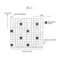
- the RSSI of the OFDM symbol not containing the reference signal within one sub-frame may be measured in the measurement of the RSRQ in the case where the interference coordination is applied, as illustrated in Fig. 7
- the RSSI of the OFDM symbol containing the reference signal within one sub-frame may be measured in the measurement of the RSRQ in the case where the interference coordination is not applied, as illustrated in Fig. 6 .
- the RSSI of the OFDM symbols #1/#2/#3/#5/#6/#8/#9/#10/#12/#13 may be measured as illustrated in Fig. 7
- the RSSI of the ODFM symbols #0/#4/#7/#11 may be measured as illustrated in Fig. 6 .
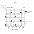
- the measurement illustrated in Fig. 8 may be performed instead of the measurement illustrated in Fig. 5 .
- a process of not measuring the RSSI at the OFDM symbols having the same transmission timing as those to which the reference signal is transmitted in the neighboring cell and a process of measuring the RSSI at other OFDM symbols may be performed.
- the OFDM symbols having the same transmission timing as those to which the reference signal is transmitted are the OFDM symbols #1/#5/#8/#12 and other OFDM symbols are the OFDM symbols #0/#2/#3/#4/#6/#7/#9/#10/#11/#13.
- the RSSI of the OFDM symbols containing the reference signal within one sub-frame may be measured, as illustrated in Fig. 6 .
- the RSSI of the OFDM symbols #0/#2/#3/#4/#6/#7/#9/#10/#11/#13 may be measured as illustrated in Fig. 8
- the RSSI of the OFDM symbols #0/#4/#7/#11 may be measured as illustrated in Fig. 6 .
- the transmission timing of the neighboring cell may be notified by control information, broadcast information or the like of the RRC from a base station apparatus eNB. Further, the transmission timing of the neighboring cell may be notified with a unit of the OFDM symbol. Moreover, as the transmission timing of the neighboring cell, a difference of relative timing between the transmission timing of the serving cell may be notified.
- the transmission timing of the neighboring cell may be designated by an autonomous detection of a user equipment UE.
- the process of measuring the RSSI of the OFDM symbols designated by the base station apparatus eNB may be performed.
- the RSSI of the OFDM symbols designated by the base station apparatus eNB may be measured, and in the measurement of the RSRQ in the case where the interference coordination is not applied, the RSSI of the OFDM symbols containing the reference signal within one sub-frame may be measured.
- the RSSI of the OFDM symbols #2/#4 may be measured, and in the measurement of the RSRQ in the case where the interference coordination is not applied, the RSSI of the ODFM symbols #0/#4/#7/#a11 may be measured, as illustrated in Fig. 6 .
- information on the OFDM symbols designated by the base station apparatus eNB may be notified by the RRC signaling. Further, as information on the OFDM symbols, OFDM symbols used in the measurement of the RSSI maybe designated and OFDM symbols not used in the measurement of the RSSI may be designated. Alternatively, as information on the OFDM symbols, information of any type may be designated as long as the OFDM symbols used in the measurement of the RSSI can be specified.
- the measurement of the above-described RSRQ and RSSI may be performed as the measurement the RSRQ and RSSI of the serving cell and as the measurement the RSRQ and RSSI of the neighboring cell.
- the above-described example indicates the measurement method for the measurement of the RSRQ of the serving cell and the neighboring cell when a user equipment 10 is in a connected state with a network (base station apparatus), that is, in a case where the user equipment 10 is in a RRC-connected state, but may be applied in the measurement of the serving cell and the neighboring cell in a case where the user equipment 10 is in an Idle state.
- a network base station apparatus
- the measurement of the neighboring cell is performed for the purpose of cell reselection.
- Fig. 9 is a functional block diagram of the user equipment 10 according to the present embodiment.
- the user equipment 10 includes a RRC signal receiving unit 101, a measurement OFDM symbol determining unit 103, a receiving unit 105, a RSSI measuring unit 107, a RSRP measuring unit 109, and a RSRQ calculating unit 111.
- the RRC signal receiving unit 101 is configured to receive a control signal of a RRC layer from the base station apparatus eNB.
- the RRC signal receiving unit 101 is configured to receive information on whether or not the interference coordination, that is, e-ICIC is applied to the cell as the control signal of the RRC layer.
- the RRC signal receiving unit 101 is configured to receive information on the sub-frame for the measurement of RSRP or RSRQ in the interference coordination, that is, e-ICIC, as the control signal of the RRC layer.
- the information notified by the control signal of the above-described RRC layer for example, the information on whether or not the interference coordination, that is, e-ICIC is applied to the cell or the information on the sub-frame for the measurement of RSRP or RSRQ in the interference coordination, that is, e-ICIC is transmitted to the measurement OFDM symbol determining unit 103.
- the measurement OFDM symbol determining unit 103 is configured to determine the OFDM symbol for measuring the RSSI.
- the measurement OFDM symbol determining unit 103 may be configured to receive the information notified by the control signal of the RRC layer from the RRC signal receiving unit 101 and determine the OFDM symbol for measuring the RSSI based on the information notified by the control signal of such RRC layer.
- the measurement OFDM symbol determining unit 103 may be configured such that all the OFDM symbols within one sub-frame are determined to be OFDM symbols for measuring the RSSI in the measurement of the RSRQ when the interference coordination is applied, as illustrated in Fig. 5 , and that the OFDM symbols containing the reference signal within one sub-frame are determined to be OFDM symbols for measuring the RSSI in the measurement of the RSRQ when the interference coordination is not applied, as illustrated in Fig. 6 .
- the measurement OFDM symbol determining unit 103 may be configured such that the OFDM symbols not containing the reference signal within one sub-frame are determined to be OFDM symbols for measuring the RSSI in the measurement of the RSRQ when the interference coordination is applied, as illustrated in Fig. 7 , and that the OFDM symbols containing the reference signal within one sub-frame are determined to be OFDM symbols for measuring the RSSI in the measurement of the RSRQ when the interference coordination is not applied.
- the measurement OFDM symbol determining unit 103 is configured to notify the RSSI measuring unit 107 of the OFDM symbols for measuring the determined RSSI.
- the receiving unit 105 is configured to receive signals transmitted from the serving cell and the neighboring cell.
- the signals received by the receiving unit 105 include the reference signals to be used in the measurement of the RSRP.
- the receiving unit 105 is configured to transmit the received signals to the RSSI measuring unit 107 and the RSRP measuring unit 109.
- the RSSI receiving unit 107 is configured to receive the OFDM symbols for measuring the RSSI from the measurement OFDM symbol determining unit 103 and to measure the RSSI. in the OFDM symbols for measuring such RSSI.
- the RSSI is the sum of the received powers of all signals such as desired signals from the serving cell, interference signals from the neighboring cell, noise signals due to thermal noise, or the like.
- the RSSI receiving unit 107 is configured to transmit the measured RSSI to the RSRQ calculating unit 111.
- the RSRP measuring unit 109 is configured to measure the RSRP of the serving cell and the neighboring cell and to transmit the measured RSRP of the serving cell and the neighboring cell to the RSRQ calculating unit 111.
- the RSRQ calculating unit 111 is configured to receive the RSSI from the RSSI measuring unit 107 and to receive the RSRP of the serving cell and the neighboring cell from the RSRP measuring unit 109.
- the RSRQ calculating unit 111 calculates the RSRQ of the serving cell and the neighboring cell based on the following Expression 3.
- RSRQ RSRP / RSSI
- the above-described example indicates the measurement method for the measurement of the RSSI and RSRQ of the serving cell and the neighboring cell when the user equipment 10 is in the connected state with the network (base station apparatus eNB), that is, in a case where the user equipment 10 is in a RRC-connected state, but may be applied in the measurement of the serving cell and the neighboring cell in a case where the user equipment 10 is in an Idle state.
- the measurement of the serving cell and the neighboring cell is performed for the purpose of the cell reselection.
- Fig. 10 is a flowchart of the measurement method in the mobile communication system according to the present embodiment.
- step S201 first, the user equipment 10 determines wether or not the sub-frame is the sub-frame to which the control of the interference coordination is applied.
- the user equipment 10 measures the RSSI in all the OFDM symbols in step S203.
- the user equipment 10 measures the RSSI in the OFDM symbols containing the reference signal in step S205.
- the user equipment 10 may calculate the RSRQ using the RSSI calculated by the flowchart.
- step S207 the user equipment 10 measures the RSRP of the serving cell and the neighboring cell.
- step S209 the user equipment 10 measures the RSRQ of the serving cell and the neighboring cell.
- the RSRQ is calculated by a following Expression 4.
- RSRQ RSRP / RSSI Note that, in the above-described S203, the user equipment 10 may measure the RSSI in the OFDM symbols not containing the reference signal, as illustrated in Fig. 7 , instead of measuring the RSSI in all the OFDM symbols.
- the above-described example indicates the measurement method of the RSRQ of the serving cell and the neighboring cell in a case where the user equipment 10 is in the connected state with the network (base station apparatus eNB), that is, in a case where the user equipment 10 is in a RRC-connected state, but may be applied in the measurement of the RSRQ of the serving cell and the neighboring cell in a case where the user equipment 10 is in the Idle state.
- the network base station apparatus eNB
- the measurement of the RSRQ of the serving cell and the neighboring cell is performed for the purpose of the cell reselection.
- the mobile communication system of the present embodiment it is possible to measure the radio quality of the serving cell and the neighboring cell with good accuracy based on whether or not the interference coordination is performed.
- the interference coordination when the interference coordination is performed, it is possible to reduce influence of the power of the reference signals from the interfering neighboring cell by measuring the RSSI in all the OFDM symbols within the sub-frame, as illustrated in Fig. 5 , resulting in measuring the RSSI or the RSRQ appropriately.
- the interference coordination when the interference coordination is not performed, it is possible to avoid that the RSSI is close to "0" and to avoid that the value of RSRQ diverges to infinity by measuring the RSSI in the OFDM symbols containing the reference signal within the sub-frame, asp illustrated in Fig. 6 , resulting in measuring, the RSSI or the RSRQ appropriately.
- the interference coordination when the interference coordination is performed, it is possible to exclude influence of the power of the reference signal from the interfering neighboring cell by measuring the RSSI in the OFDM symbols not containing the reference signal within the sub-frame, as illustrated in Fig. 7 , resulting in measuring the RSSI or the RSRQ appropriately.
- the interference coordination when the interference coordination is not performed, it is possible to avoid that the RSSI. is close to "0" and to avoid that the value of RSRQ diverges to infinity by measuring the RSSI in the OFDM symbols containing the reference signal within the sub-frame, as illustrated in Fig. 6 , resulting in measuring the RSSI or the RSRQ appropriately.
- both the RSRQ calculated from the RSSI measured in the OFDM symbols illustrated in Fig. 5 and the RSRQ calculated from the RSSI measured in the OFDM symbols illustrated in Fig. 6 may be measured, when the interference coordination is performed.
- the above-described examples indicate the example of measuring the RSSI in the OFDM symbols illustrated in Fig. 7 when the interference coordination is performed and the example of measuring the RSSI in the OFDM symbols illustrated in Fig. 6 when the interference coordination is not performed.
- both the RSRQ calculated from the RSSI measured in the OFDM symbols illustrated in Fig. 7 and the RSRQ calculated from the RSSI measured in the OFDM symbols illustrated in Fig. 6 may be measured, when the interference coordination is performed.
- the above-described measurement of the RSSI and the RSRQ when the interference coordination is performed may be applied depending on whether or not "MRSFN sub-frame" is set in the neighboring cell.
- the user equipment 10 may measure the RSRQ calculated from the RSSI measured in the OFDM symbols illustrated in Fig. 5 or Fig. 7 . In other cases, the user equipment 10 may measure the RSRQ calculated from the RSSI measured in the OFDM symbols illustrated in Fig. 6 .
- the measurement of the RSSI and the RSRQ when the above-described interference coordination is performed may be applied depending on whether or not the user equipment 10 has a function of removing the interference by the reference signal of the neighboring cell.
- the user equipment 10 may measure the RSRQ calculated from the RSSI measured in the OFDM symbols illustrated in Fig. 5 or Fig. 7 . In other cases, the user equipment 10 may measure the RSRQ calculated from the RSSI measured in the OFDM symbols illustrated in Fig. 6 .
- the measurement of the RSSI and the RSRQ when the above-described interference coordination is performed may be applied at the time of being designated from the base station apparatus eNB.
- the user equipment 10 may measure the RSRQ calculated from the RSSI measured in the OFDM symbols illustrated in Fig. 5 or Fig. 7 . In other cases, the user equipment 10 may measure the RSRQ calculated from the RSSI measured in the OFDM symbols illustrated in Fig. 6 .
- the control may be performed as to whether or not to perform the measurement of RSSI and RSRQ to be performed depending on whether or not the above-described interference coordination is performed for each cell which is a measurement target and may be performed as to whether or not to perform the measurement of RSSI and RSRQ to be performed depending on whether or not the above-described interference coordination is performed for each sub-frame which is the measurement target.
- the user equipment 10 selects the OFDM symbols for measuring the RSSI and measures the RSSI for the OFDM symbols so as not to be affected by the reference signal transmitted from the neighboring cell.
- the user equipment 10 may measure the power of the reference signal transmitted from the neighboring cell and measure the RSSI in consideration of the reference signal transmitted from the neighboring cell.
- the final RSSI when representing the received power of the reference signal transmitted from the neighboring cell as "PowerNeighbor, RS", the final RSSI may be calculated as follows.
- the user equipment 10 may calculate the RSSI so as to remove the power due to the reference signal transmitted from the neighboring cell, when the interference coordination is performed.
- the user equipment 10 may calculate the RSSI by subtracting the power by the reference signal transmitted from the neighboring cell from the measured RSSI when the interference coordination is performed.
- the process of calculating the RSSI so as to remove the power due to the reference signal transmitted from the neighboring cell may be performed on only the OFDM symbols affected by the reference signal transmitted from the neighboring cell.
- the process of calculating the RSSI so as to remove the power due to the reference signal transmitted from the neighboring cell may be performed. In other cases, the process of calculating the RSSI so as to remove the power due to the reference signal transmitted from the neighboring cell may not be performed.
- the present invention is not limited to the LTE, but may also be applied to other mobile communication systems.
- the present invention is not limited to the mobile communication system in which the center frequency of each cell is identical, but may be applied to measurement of different frequencies in a case where the frequencies are different.
- the present invention may be applied to measurement of different radio access technologies (RAT) in a case where RATs of cells are different.
- RAT radio access technologies
- a first characteristic of the present embodiment is a user equipment 10 configured to measure a radio quality of a serving cell and a neighboring cell including a RSSI measuring unit 107 that is configured, with regard to a predetermined sub-frame, to measure the radio quality of the serving cell and the neighboring cell for all OFDM symbols (time symbols) within the predetermined sub-frame and, with regard to sub-frames other than the predetermined sub-frame, to measure the radio quality of the serving cell and the neighboring cell for OFDM symbols containing a reference signal within the sub-frames.
- a RSSI measuring unit 107 that is configured, with regard to a predetermined sub-frame, to measure the radio quality of the serving cell and the neighboring cell for all OFDM symbols (time symbols) within the predetermined sub-frame and, with regard to sub-frames other than the predetermined sub-frame, to measure the radio quality of the serving cell and the neighboring cell for OFDM symbols containing a reference signal within the sub-frames.
- the predetermined sub-frame may be a sub-frame for measurement in a case where interference coordination is applied.
- the predetermined sub-frame may be notified by a RRC signaling from a base station apparatus eNB.
- the above-described radio quality may be a RSSI, and more specifically, the radio quality may be a RSSI using for a calculation of a RSRP.
- the predetermined sub-frame may be a sub-frame for measurement of RSRP and RSRQ.
- the predetermined sub-frame may be a specified sub-frame for measurement of the serving cell.
- the predetermined sub-frame may be a specified sub-frame for measurement of the neighboring cell.
- a second characteristic of the present embodiment is a user equipment 10 configured to measure a radio quality of a serving cell and a neighboring cell including a RSSI measuring unit 107 that is configured, with regard to a predetermined sub-frame, to measure the radio quality of the serving cell and the neighboring cell for OFDM symbols not containing a reference signal within the predetermined sub-frame and, with regard to sub-frames other than the predetermined sub-frame, to measure the radio quality of the serving cell and the neighboring cell for OFDM symbols containing the reference signal within the sub-frames.
- a RSSI measuring unit 107 that is configured, with regard to a predetermined sub-frame, to measure the radio quality of the serving cell and the neighboring cell for OFDM symbols not containing a reference signal within the predetermined sub-frame and, with regard to sub-frames other than the predetermined sub-frame, to measure the radio quality of the serving cell and the neighboring cell for OFDM symbols containing the reference signal within the sub-frames.
- a third characteristic of the present embodiment is a user equipment 10 configured to measure a radio quality of a serving cell and a neighboring cell including a RSSI measuring unit 107 that is configured to measure the radio quality of the serving cell and the neighboring cell when the radio quality of the serving cell and the neighboring cell is calculated from a received power of a reference signal of the serving cell and the neighboring cell and a total of received powers within a band, wherein the RSSI measuring unit 107 calculates the total of received powers within the band such that the received power of the reference signal of the neighboring cell is not included in the total of received powers within the band.
- a fourth characteristic of the present embodiment is a measurement method of measuring a radio quality of a serving cell and a neighboring cell, the method including: step A of determining OFDM symbols for measuring the radio quality of the serving cell and the neighboring cell; and step B of measuring the radio quality of the serving cell and the neighboring cell for the determined OFDM symbols, wherein the OFDM symbols for measuring the radio quality of the serving cell and the neighboring cell are determined depending on whether or not interference coordination is applied in the step B.
- the operation of the above-described user equipment 10 (UE) and the base station apparatus eNB may be implemented by a hardware, by a software module executed by a processor, and by the combination of the both.
- the software module may be arranged in a storage medium of an arbitrary format such as RAM (Random Access Memory), a flash memory, ROM (Read Only Memory), EPROM (Erasable Programmable ROM), EEPROM (Electronically Erasable and Programmable ROM), a register, a hard disk, a removable disk, and CD-ROM.
- RAM Random Access Memory
- flash memory ROM (Read Only Memory)
- EPROM Erasable Programmable ROM
- EEPROM Electrical Erasable and Programmable ROM
- register a hard disk, a removable disk, and CD-ROM.
- the storage medium is connected to the processor so that the processor can write and read information into and from the storage medium.
- such storage medium may also be accumulated in the processor.
- the storage medium and processor may be arranged in ASIC.
- ASIC may be arranged in the user equipment 10 (UE) or the base station apparatus eNB.
- such storage medium or processor may be arranged, as a discrete component, in the user equipment 10 (UE) or the base station apparatus eNB.
Landscapes
- Engineering & Computer Science (AREA)
- Signal Processing (AREA)
- Computer Networks & Wireless Communication (AREA)
- Quality & Reliability (AREA)
- Physics & Mathematics (AREA)
- Electromagnetism (AREA)
- Mobile Radio Communication Systems (AREA)
- Monitoring And Testing Of Transmission In General (AREA)
- Noise Elimination (AREA)
Applications Claiming Priority (2)
| Application Number | Priority Date | Filing Date | Title |
|---|---|---|---|
| JP2011003475 | 2011-01-11 | ||
| PCT/JP2012/050354 WO2012096296A1 (fr) | 2011-01-11 | 2012-01-11 | Dispositif utilisateur et procédé de mesure |
Publications (2)
| Publication Number | Publication Date |
|---|---|
| EP2665332A1 true EP2665332A1 (fr) | 2013-11-20 |
| EP2665332A4 EP2665332A4 (fr) | 2015-12-16 |
Family
ID=46507191
Family Applications (3)
| Application Number | Title | Priority Date | Filing Date |
|---|---|---|---|
| EP12734020.6A Withdrawn EP2665332A4 (fr) | 2011-01-11 | 2012-01-11 | Dispositif utilisateur et procédé de mesure |
| EP12734738.3A Withdrawn EP2665333A4 (fr) | 2011-01-11 | 2012-01-11 | Dispositif utilisateur et dispositif de mesure |
| EP18163893.3A Withdrawn EP3361823A1 (fr) | 2011-01-11 | 2012-01-11 | Équipement utilisateur et procédé de mesure |
Family Applications After (2)
| Application Number | Title | Priority Date | Filing Date |
|---|---|---|---|
| EP12734738.3A Withdrawn EP2665333A4 (fr) | 2011-01-11 | 2012-01-11 | Dispositif utilisateur et dispositif de mesure |
| EP18163893.3A Withdrawn EP3361823A1 (fr) | 2011-01-11 | 2012-01-11 | Équipement utilisateur et procédé de mesure |
Country Status (9)
| Country | Link |
|---|---|
| US (2) | US9497676B2 (fr) |
| EP (3) | EP2665332A4 (fr) |
| JP (2) | JP5810100B2 (fr) |
| KR (2) | KR20160079139A (fr) |
| CN (2) | CN103299674B (fr) |
| AU (1) | AU2012206093B8 (fr) |
| CA (1) | CA2824275A1 (fr) |
| MX (1) | MX2013008057A (fr) |
| WO (2) | WO2012096299A1 (fr) |
Cited By (3)
| Publication number | Priority date | Publication date | Assignee | Title |
|---|---|---|---|---|
| EP2876937A4 (fr) * | 2012-07-20 | 2016-03-23 | Sony Corp | Appareil de communication sans fil, appareil de traitement d'informations, système de communication, procédé de calcul de qualité de communication et programme |
| WO2023023511A1 (fr) * | 2021-08-16 | 2023-02-23 | Qualcomm Incorporated | Qualité reçue de signal de référence pour signaux de référence complètement chargés |
| US12388542B2 (en) | 2021-08-16 | 2025-08-12 | Qualcomm Incorporated | Reference signal received quality for fully loaded reference signals |
Families Citing this family (19)
| Publication number | Priority date | Publication date | Assignee | Title |
|---|---|---|---|---|
| JP5870891B2 (ja) * | 2012-10-11 | 2016-03-01 | ソニー株式会社 | 情報処理装置、無線通信装置、通信システムおよび情報処理方法 |
| CN104067661B (zh) * | 2012-11-02 | 2018-06-19 | 华为技术有限公司 | 接收信号强度指示值的获取方法及用户设备 |
| US9398480B2 (en) * | 2012-11-02 | 2016-07-19 | Telefonaktiebolaget L M Ericsson (Publ) | Methods of obtaining measurements in the presence of strong and/or highly varying interference |
| US9503216B2 (en) | 2012-11-02 | 2016-11-22 | Telefonaktiebolaget L M Ericsson (Publ) | Methods and devices related to effective measurements |
| JP5971111B2 (ja) * | 2012-12-20 | 2016-08-17 | 富士通株式会社 | 移動通信端末及びセル判定方法 |
| JP6138486B2 (ja) * | 2012-12-28 | 2017-05-31 | 株式会社Nttドコモ | 移動機、受信方法、基地局及び移動機動作制御方法 |
| JP6279207B2 (ja) * | 2013-01-10 | 2018-02-14 | 富士通株式会社 | 受信装置及び干渉雑音電力推定方法 |
| CN105075159B (zh) * | 2013-03-22 | 2018-04-10 | Lg电子株式会社 | 在无线通信系统中执行干扰协调的方法和设备 |
| US10237879B2 (en) | 2013-07-09 | 2019-03-19 | Lg Electronics Inc. | Method for channel state report in wireless communication system and apparatus therefor |
| CN105659694B (zh) | 2013-12-25 | 2020-09-04 | 松下电器(美国)知识产权公司 | 移动台及接收质量测量方法 |
| WO2015113273A1 (fr) * | 2014-01-29 | 2015-08-06 | 华为技术有限公司 | Procédé et dispositif de mesure pour gestion de ressources radio |
| US9838951B2 (en) | 2014-03-14 | 2017-12-05 | Intel Corporation And Intel Ip Corporation | Apparatuses, systems, and methods for measuring quality of cell discovery signal |
| US9713049B2 (en) * | 2014-04-28 | 2017-07-18 | Intel IP Corporation | User equipment and methods for measurement of reference signal received quality |
| WO2015171216A1 (fr) * | 2014-05-09 | 2015-11-12 | Intel IP Corporation | Techniques de signalisation pour mesures de qualité de signal de référence reçu (rsrq) |
| CN105101282A (zh) * | 2014-05-21 | 2015-11-25 | 中兴通讯股份有限公司 | 发现信号测量的方法、装置及用户终端 |
| EP3190732B1 (fr) | 2014-09-02 | 2019-05-15 | LG Electronics Inc. | Procédé et dispositif de transmission de signal de synchronisation par un terminal de dispositif à dispositif dans un système de communications sans fil |
| US10009925B2 (en) * | 2014-10-03 | 2018-06-26 | Qualcomm Incorporated | Physical layer procedures for LTE in unlicensed spectrum |
| WO2017119794A1 (fr) * | 2016-01-08 | 2017-07-13 | 엘지전자 주식회사 | Procédé de notification d'informations d'état de canal, et équipement d'utilisateur l'exécutant |
| CN109392170B (zh) * | 2017-08-11 | 2021-12-21 | 展讯通信(上海)有限公司 | 资源分配方法及装置、用户设备、基站、可读存储介质 |
Family Cites Families (10)
| Publication number | Priority date | Publication date | Assignee | Title |
|---|---|---|---|---|
| CN101287275B (zh) * | 2007-04-11 | 2011-05-11 | 中兴通讯股份有限公司 | 一种基于cdma系统的下行方向邻区干扰的测量方法 |
| US9271174B2 (en) | 2007-08-07 | 2016-02-23 | Intel Deutschland Gmbh | Communication device performing measurements using assigned time slots |
| KR101153709B1 (ko) | 2008-03-31 | 2012-06-07 | 닛본 덴끼 가부시끼가이샤 | 무선통신 시스템, 기지국, 이동국 및 송신파라미터 결정방법 |
| US9867203B2 (en) * | 2008-07-11 | 2018-01-09 | Qualcomm Incorporated | Synchronous TDM-based communication in dominant interference scenarios |
| CN101784116B (zh) * | 2009-01-19 | 2012-07-04 | 华为技术有限公司 | 一种探测参考信号资源分配的方法、系统和设备 |
| US9253651B2 (en) * | 2009-05-01 | 2016-02-02 | Qualcom Incorporated | Transmission and detection of overhead channels and signals in a wireless network |
| US8670432B2 (en) * | 2009-06-22 | 2014-03-11 | Qualcomm Incorporated | Methods and apparatus for coordination of sending reference signals from multiple cells |
| AU2011233858B2 (en) * | 2010-03-29 | 2015-01-29 | Lg Electronics Inc. | Method and apparatus for measurement for inter-cell interference coordination in radio communication system |
| US9609536B2 (en) * | 2010-04-13 | 2017-03-28 | Qualcomm Incorporated | Measurement of received power and received quality in a wireless communication network |
| US20120113961A1 (en) * | 2010-11-08 | 2012-05-10 | Motorola Mobility, Inc. | Interference Measurements in Enhanced Inter-Cell Interference Coordination Capable Wireless Terminals |
-
2012
- 2012-01-11 CN CN201280005089.XA patent/CN103299674B/zh active Active
- 2012-01-11 JP JP2012552743A patent/JP5810100B2/ja active Active
- 2012-01-11 MX MX2013008057A patent/MX2013008057A/es active IP Right Grant
- 2012-01-11 WO PCT/JP2012/050357 patent/WO2012096299A1/fr not_active Ceased
- 2012-01-11 EP EP12734020.6A patent/EP2665332A4/fr not_active Withdrawn
- 2012-01-11 JP JP2012552740A patent/JP5756129B2/ja active Active
- 2012-01-11 EP EP12734738.3A patent/EP2665333A4/fr not_active Withdrawn
- 2012-01-11 CA CA2824275A patent/CA2824275A1/fr not_active Abandoned
- 2012-01-11 WO PCT/JP2012/050354 patent/WO2012096296A1/fr not_active Ceased
- 2012-01-11 CN CN201280005081.3A patent/CN103299708B/zh active Active
- 2012-01-11 KR KR1020167016815A patent/KR20160079139A/ko not_active Withdrawn
- 2012-01-11 AU AU2012206093A patent/AU2012206093B8/en not_active Ceased
- 2012-01-11 KR KR1020137018797A patent/KR20130117833A/ko not_active Ceased
- 2012-01-11 US US13/979,176 patent/US9497676B2/en active Active
- 2012-01-11 EP EP18163893.3A patent/EP3361823A1/fr not_active Withdrawn
- 2012-01-11 US US13/979,191 patent/US9426706B2/en active Active
Non-Patent Citations (1)
| Title |
|---|
| See references of WO2012096296A1 * |
Cited By (3)
| Publication number | Priority date | Publication date | Assignee | Title |
|---|---|---|---|---|
| EP2876937A4 (fr) * | 2012-07-20 | 2016-03-23 | Sony Corp | Appareil de communication sans fil, appareil de traitement d'informations, système de communication, procédé de calcul de qualité de communication et programme |
| WO2023023511A1 (fr) * | 2021-08-16 | 2023-02-23 | Qualcomm Incorporated | Qualité reçue de signal de référence pour signaux de référence complètement chargés |
| US12388542B2 (en) | 2021-08-16 | 2025-08-12 | Qualcomm Incorporated | Reference signal received quality for fully loaded reference signals |
Also Published As
| Publication number | Publication date |
|---|---|
| EP2665333A1 (fr) | 2013-11-20 |
| MX2013008057A (es) | 2013-08-09 |
| KR20160079139A (ko) | 2016-07-05 |
| US9426706B2 (en) | 2016-08-23 |
| EP3361823A1 (fr) | 2018-08-15 |
| CN103299708B (zh) | 2016-12-14 |
| EP2665332A4 (fr) | 2015-12-16 |
| CA2824275A1 (fr) | 2012-07-19 |
| JP5756129B2 (ja) | 2015-07-29 |
| JPWO2012096299A1 (ja) | 2014-06-09 |
| NZ613257A (en) | 2014-11-28 |
| WO2012096296A1 (fr) | 2012-07-19 |
| JP5810100B2 (ja) | 2015-11-11 |
| US20130336149A1 (en) | 2013-12-19 |
| WO2012096299A1 (fr) | 2012-07-19 |
| CN103299674B (zh) | 2016-06-15 |
| EP2665333A4 (fr) | 2017-09-06 |
| KR20130117833A (ko) | 2013-10-28 |
| CN103299674A (zh) | 2013-09-11 |
| CN103299708A (zh) | 2013-09-11 |
| US9497676B2 (en) | 2016-11-15 |
| JPWO2012096296A1 (ja) | 2014-06-09 |
| AU2012206093B2 (en) | 2015-02-12 |
| AU2012206093B8 (en) | 2015-05-28 |
| US20130336148A1 (en) | 2013-12-19 |
Similar Documents
| Publication | Publication Date | Title |
|---|---|---|
| AU2012206093B2 (en) | User equipment and measurement method | |
| US8824969B2 (en) | Radio base station and mobile communication method | |
| EP2984864B1 (fr) | Procédés permettant d'effectuer des mesures inter-fréquences en état de repos | |
| EP2317799A1 (fr) | Station mobile et procédé de communication mobile | |
| EP3255920B1 (fr) | Station mobile et procédé de communication mobile | |
| US8731558B2 (en) | Mobile station, radio base station, and mobile communication method | |
| AU2011236892B2 (en) | Radio base station, mobile station, and communication control method | |
| US9456392B2 (en) | Mobile station and communication method | |
| EP2706785B1 (fr) | Équipement d'utilisateur et procédé de communication mobile | |
| US8996006B2 (en) | Mobile station, radio base station, mobile communication system, and mobile communication method | |
| US20110218009A1 (en) | Mobile communication method, mobile communication system and radio base station | |
| NZ613257B2 (en) | User equipment and measurement method |
Legal Events
| Date | Code | Title | Description |
|---|---|---|---|
| PUAI | Public reference made under article 153(3) epc to a published international application that has entered the european phase |
Free format text: ORIGINAL CODE: 0009012 |
|
| 17P | Request for examination filed |
Effective date: 20130807 |
|
| AK | Designated contracting states |
Kind code of ref document: A1 Designated state(s): AL AT BE BG CH CY CZ DE DK EE ES FI FR GB GR HR HU IE IS IT LI LT LU LV MC MK MT NL NO PL PT RO RS SE SI SK SM TR |
|
| DAX | Request for extension of the european patent (deleted) | ||
| RA4 | Supplementary search report drawn up and despatched (corrected) |
Effective date: 20151117 |
|
| RIC1 | Information provided on ipc code assigned before grant |
Ipc: H04B 17/318 20150101AFI20151111BHEP Ipc: H04L 5/00 20060101ALN20151111BHEP Ipc: H04W 24/10 20090101ALN20151111BHEP Ipc: H04W 36/00 20090101ALN20151111BHEP Ipc: H04B 17/382 20150101ALN20151111BHEP Ipc: H04J 11/00 20060101ALN20151111BHEP |
|
| 17Q | First examination report despatched |
Effective date: 20171212 |
|
| RAP1 | Party data changed (applicant data changed or rights of an application transferred) |
Owner name: NTT DOCOMO, INC. |
|
| RIN1 | Information on inventor provided before grant (corrected) |
Inventor name: NISHIKAWA, DAISUKE Inventor name: ABE, TETSUSHI Inventor name: ISHII, HIROYUKI |
|
| RIC1 | Information provided on ipc code assigned before grant |
Ipc: H04B 17/318 20150101AFI20151111BHEP Ipc: H04W 36/00 20090101ALN20151111BHEP Ipc: H04J 11/00 20060101ALN20151111BHEP Ipc: H04B 17/382 20150101ALN20151111BHEP Ipc: H04L 5/00 20060101ALN20151111BHEP Ipc: H04W 24/10 20090101ALN20151111BHEP |
|
| RIC1 | Information provided on ipc code assigned before grant |
Ipc: H04W 36/00 20090101ALN20151111BHEP Ipc: H04B 17/318 20150101AFI20151111BHEP Ipc: H04B 17/382 20150101ALN20151111BHEP Ipc: H04J 11/00 20060101ALN20151111BHEP Ipc: H04L 5/00 20060101ALN20151111BHEP Ipc: H04W 24/10 20090101ALN20151111BHEP |
|
| GRAP | Despatch of communication of intention to grant a patent |
Free format text: ORIGINAL CODE: EPIDOSNIGR1 |
|
| INTG | Intention to grant announced |
Effective date: 20200421 |
|
| RIC1 | Information provided on ipc code assigned before grant |
Ipc: H04L 5/00 20060101ALN20200406BHEP Ipc: H04W 24/10 20090101ALN20200406BHEP Ipc: H04B 17/382 20150101ALN20200406BHEP Ipc: H04J 11/00 20060101ALN20200406BHEP Ipc: H04B 17/318 20150101AFI20200406BHEP Ipc: H04W 36/00 20090101ALN20200406BHEP |
|
| STAA | Information on the status of an ep patent application or granted ep patent |
Free format text: STATUS: THE APPLICATION IS DEEMED TO BE WITHDRAWN |
|
| 18D | Application deemed to be withdrawn |
Effective date: 20200902 |