EP2665970B1 - Brûleur et fourneau le comprenant - Google Patents
Brûleur et fourneau le comprenant Download PDFInfo
- Publication number
- EP2665970B1 EP2665970B1 EP12701713.5A EP12701713A EP2665970B1 EP 2665970 B1 EP2665970 B1 EP 2665970B1 EP 12701713 A EP12701713 A EP 12701713A EP 2665970 B1 EP2665970 B1 EP 2665970B1
- Authority
- EP
- European Patent Office
- Prior art keywords
- burner
- fuel
- exit openings
- flame
- furnace
- Prior art date
- Legal status (The legal status is an assumption and is not a legal conclusion. Google has not performed a legal analysis and makes no representation as to the accuracy of the status listed.)
- Active
Links
Images
Classifications
-
- F—MECHANICAL ENGINEERING; LIGHTING; HEATING; WEAPONS; BLASTING
- F23—COMBUSTION APPARATUS; COMBUSTION PROCESSES
- F23D—BURNERS
- F23D14/00—Burners for combustion of a gas, e.g. of a gas stored under pressure as a liquid
- F23D14/20—Non-premix gas burners, i.e. in which gaseous fuel is mixed with combustion air on arrival at the combustion zone
- F23D14/22—Non-premix gas burners, i.e. in which gaseous fuel is mixed with combustion air on arrival at the combustion zone with separate air and gas feed ducts, e.g. with ducts running parallel or crossing each other
-
- F—MECHANICAL ENGINEERING; LIGHTING; HEATING; WEAPONS; BLASTING
- F23—COMBUSTION APPARATUS; COMBUSTION PROCESSES
- F23D—BURNERS
- F23D14/00—Burners for combustion of a gas, e.g. of a gas stored under pressure as a liquid
- F23D14/46—Details
- F23D14/48—Nozzles
- F23D14/58—Nozzles characterised by the shape or arrangement of the outlet or outlets from the nozzle, e.g. of annular configuration
-
- F—MECHANICAL ENGINEERING; LIGHTING; HEATING; WEAPONS; BLASTING
- F23—COMBUSTION APPARATUS; COMBUSTION PROCESSES
- F23D—BURNERS
- F23D14/00—Burners for combustion of a gas, e.g. of a gas stored under pressure as a liquid
- F23D14/46—Details
- F23D14/48—Nozzles
- F23D14/58—Nozzles characterised by the shape or arrangement of the outlet or outlets from the nozzle, e.g. of annular configuration
- F23D14/583—Nozzles characterised by the shape or arrangement of the outlet or outlets from the nozzle, e.g. of annular configuration of elongated shape, e.g. slits
Definitions
- the invention relates to burners for furnaces.
- Such burners are known and widely used for high and/or low temperature furnaces such as industrial cracking installations or heaters or steam reformers.
- a high temperature furnace is understood to be a furnace for industrial production use, thus not on laboratory scale, which operates at relatively high temperatures.
- the temperature operation range is between approximately 1100 °C and approximately 1400 °C.
- the operation temperature is rather critical to maintain.
- Such burners may also be used in low temperature furnaces operating at temperatures outside the range of 1100 °C - 1400 °C.
- the burners are wall mounted or floor mounted or roof mounted in the radiant section of the firebox. The burners produce a flame front that heats the furnace.
- process tubes are arranged through which product to be processed, e.g.
- burners are usually positioned in a relatively compact arrangement.
- a drawback of the burners and/or their relatively compact arrangement is that flame-to-flame interaction or flame rollover towards the process tubes may occur that even may reach the tubes. This significantly decreases the efficiency of the process and the lifetime of the tubes. Due to flame rollover, the cokes forming inside the tubes is accelerated which reduces the time interval between decoke cycles, the efficiency of the process and the capacity of the furnace. Further, due to flame impingement on process tubes the atmosphere outside the tubes is alternating reducing/oxidizing resulting in tube material degradation. This increases the costs and reduces the furnace availability and/or capacity.
- An object of the invention is to provide a burner that obviates at least one of the above mentioned drawbacks.
- the invention provides for a burner for a furnace comprising at least one supply channel for supplying an oxidizing medium and a plurality of peripheral fuel supply channels, wherein the oxidizing medium supply channel and the fuel supply channels have exit openings arranged adjacent each other at a burner end surface for forming during use upon reaction of supplied fuel with supplied oxidizing medium a flame front, wherein the exit opening of the oxidizing medium supply channel and the exit openings of the fuel supply channels are asymmetrically arranged with respect to any plane arranged transverse to the end surface of the burner and extending through a burner central axis whereby the distribution of the fuel exit openings and/or the dimension of the fuel exit openings and/or the exit angle of the fuel exit openings and/or the shape of the fuel exit openings are arranged asymmetrically to said any plane, such that during use a flame front is created that is asymmetrical with respect to said any plane.
- known burners are configured to produce flames with symmetrical flame fronts.
- known burners need to comply to with burner standards in which symmetrical flame shapes (such as conical, cylindrical or fish tail shapes) are guaranteed.
- symmetrical flame shapes such as conical, cylindrical or fish tail shapes
- Such burner standard is for instance defined in " Burners for Fired Heaters in General Refinery Services, API Recommended Practice 535 (Second Edition, January 2006 )”.
- Such burners are for instance known from US 2003/148236 which describes an ultra low NOx burner, wherein around a large scale vortex device with a fuel and oxidant supply, multiple fuel stage lances are provided.
- the ultra low NOx gaseous fuel burner for process heating applications as disclosed in US 2003/148236 enables non-luminous, uniform and combustion space filling flame with extremely low NOx emissions. This is accomplished by using a flame stabilizer for maintaining the overall flame stability and multiple uniformly spaced and diverging fuel lances downstream to inject balanced fuel in several turbulent jets inside the furnace space for creating massive internal flue gas recirculation.
- US 2007/254251 describes an ultra low NOx burner with a staggered angular placement of fuel nozzles and oxidant nozzles at circumferential locations with respect to the burner assembly axis.
- the fuel nozzles may be provided on a different radial distance from the burner assembly nozzle or at the same distance.
- oxy-fuel flame stabilizers may be installed in the burner tile to provide flame stability during oxy-fuel firing.
- the flame shape is determined by the burner tile, the drilling of the gas tip and the aerodynamics of the burner.
- Round burner tiles are used to produce a conical or cylindrical flame shape.
- Flat flame burners are designed with rectangular burner tiles and produce a fish tail shaped flame. These burners are used when firing close to refractory walls or where the tube clearance is limited.
- symmetry and asymmetry of the flame front are based on the definition of three dimensional reflection symmetry.
- Three dimensional reflection symmetry is defined as symmetry of reflection around a plane of symmetry.
- two dimensional reflection symmetry may be defined as symmetry of reflection around a line or axis and thus clearly distinguishes from three dimensional reflection symmetry.
- the symmetry plane transverse to the end surface of the burner is defined as a symmetry plane of a burner tile, such as a round burner tile or a rectangular burner tile, of the burner, arranged at the end surface of the burner.
- the burner at least the end surface of the burner including the exit opening of the oxidizing medium supply channel and the exit openings of the fuel supply channels, has no symmetry plane. Therefore, the flame front generated by the burner according to the invention has no symmetry plane as well. With such a burner the drawbacks of the prior art burners are at least partly overcome such that interaction of the flame fronts of adjacent burners is obviated and/or at least minimized, thereby reducing the risk on flame rollover.
- the fuel exit openings are asymmetrically arranged.
- the capacity of the fuel exit openings may differ, e.g. large capacity openings and small capacity openings, and the capacity is asymmetrically arranged.
- the fuel exit openings itself may geometrically have a symmetrical distribution with respect to the symmetry plane, but there may be a difference between small capacity openings and large capacity openings resulting in an asymmetrical distribution of the capacity.
- the invention is advantageously applied in furnaces for which it is critical to obtain the operation temperature of the firebox.
- This temperature can either be relatively high in a high temperature furnace or relatively low in a low temperature furnace.
- the geometrical distribution of the fuel exit openings may be asymmetrical with respect to the symmetry plane, resulting in an asymmetrical flame front.
- an asymmetrical flame front may be formed.
- the dimension of the exit openings may be asymmetrically arranged with respect to the symmetry plane, resulting in an asymmetrical flame front.
- the fuel exit openings may be symmetrically arranged with respect to the symmetry plane, but by providing different dimensions of the exit openings that are asymmetrically distributed with respect to the symmetry plane, an asymmetrical flame front may be created.
- exit angles of the exit openings may be asymmetrically distributed with respect to the symmetry plane to create an asymmetrical flame front.
- the shape of the exit openings may be asymmetrically distributed with respect to the symmetry plane to create an asymmetrical flame front.
- the asymmetrical arrangement of the fuel exit openings can be provided relatively easily.
- the end tips are usually exchangeable, so the arrangement of the exit openings may be varied by exchanging the end tips.
- different end tips are provided to create an asymmetrical flame front.
- the end tips may differ in capacity, dimension of the exit openings, number of the exit openings, exit angle of the exit openings, shape of the exit openings, etc.
- the invention further relates to a furnace comprising at least one burner providing an asymmetrical flame front.
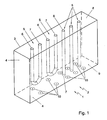
- Fig. 1 shows a furnace 1 comprising a firebox or radiant section 2.
- the firebox 2 is here provided as a large rectangular closed chamber 3.
- the chamber 3 is about 3 to 4 meters wide, about 10 to 15 meters high and about 10 to 20 meters long.
- a row of tubular piping 5 is arranged.
- the tubular piping 5 can have an entrance opening 6 and a discharge opening 7 both arranged at a top side 8 of the chamber 3.
- the tubular piping 5 may then be arranged in a U-shape.
- the tubular piping 5 may have the entrance opening 6 at the top side 8 of the chamber 3 and may have the discharge opening 7 at a bottom side 9 of the chamber 3.
- other arrangements are possible for the tubular piping.
- a row of burners 10 is arranged in the walls 4, here the floor.
- the burners may be arranged on the side walls or on the roof walls.
- the burners 10 are thus arranged on both sides of the tubular piping 5 and heat the tubular piping from both sides.
- the burners may be arranged between lanes of tubular piping.
- the burners 10 produce a flame front that heats the chamber 3 and the tubular piping 5 arranged in it.
- the chamber 3 is heated up to approximately 1100 °C to 1400 °C for a high temperature furnace.
- a stream comprising hydrocarbons, such as ethane, propane or butane is transported through the tubular piping 5.
- this stream is transported with a velocity of approximately 200 m/s through the piping 5.
- the temperature of the stream at the entrance opening 6 is typically 500 °C to 600 °C.
- the temperature of the stream is heated up to approximately 800 °C to 900 °C to attain a chemical reaction to create e.g. ethylene or propylene.
- the maximum temperature for the alloy of the tubular piping is about 1100 °C. Therefore, it is important that the flame front does not reach the tubular piping 5, because then the temperature on the material would become too high and/or sediment is formed on the inner sides of the tubular piping that decreases the efficiency of the reaction. In view of a high efficiency the burners 10 are placed relatively close to each other, however, then flame rollover may occur, which may decrease the life time, efficiency and/or capacity of the piping 5 and/or the furnace 2.
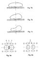
- Fig. 7a and Fig. 8a show schematically a cross section of a flame envelope of a standard symmetrical prior art burner.
- Fig. 7a shows the flame envelope of a side wall mounted symmetrical prior art burner.
- Fig. 8a shows the flame envelopes of symmetrical prior art burners that are placed between lanes of tubular piping 5.
- the tubular piping 5 may extend upwardly and the prior art burners may be arranged on the floor. Due to the symmetry of the flame envelopes, flame-to-flame interaction may occur at region C.
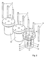
- Fig. 2 shows the burners 10 and the piping 5. Although the distance between the end surface 11 and the piping 5 is limited, typically approximately 0.5 to approximately 2 meters, the flame front may not extend onto the piping 5.
- the burner 10 comprises a supply channel 12 for oxidizing medium, e.g. combustion air and a plurality of fuel supply channels 13.
- the fuel supply channels 13 are arranged peripheral with respect to the oxidizing medium supply channel 12.
- the supply channels 12, 13 have exit openings 14, 15 respectively that terminate at the burner end surface 11.
- the exit openings 14, 15 are arranged adjacent each other such that, during use, upon reaction of supplied fuel with supplied oxidizing medium a flame front is formed.
- the fuel exit openings 15 may terminate on the end surface 11, or may terminate slightly outside the end surface 11, e.g. when the fuel supply channel 13 extends somewhat from the end surface 11, or the fuel exit openings 15 may terminate inside the end surface 11, e.g. when the fuel supply channel 13 ends somewhat upstream of the end surface 11.
- Many variants are possible and are considered to fall within the scope of the exit openings 14, 15 arranged at the burner end surface 11.
- oxidizing medium is supplied via the oxidizing medium supply channel 12 and discharged via the oxidizing medium exit opening 14.
- the fuel is supplied via the fuel supply channels 13 and is injected via the fuel exit openings 15. The fuel and the oxidizing medium will react and a flame front is created that heats the chamber 3.
- the flame front is asymmetrical, e.g. egg-shaped or concave shaped with inward curvature, etc.
- Fig. 7b, Fig. 7c and Fig. 8b show examples of asymmetrical flame envelopes from asymmetrical burners. With an asymmetrical flame front, the interaction with flame fronts of neighbouring burners 10 remains limited, which reduces the risk on flame rollover wherein the flame front reaches the piping 5. In particular Fig. 8b shows that the interaction between neighbouring asymmetrical flame envelopes may be absent.
- the fuel exit openings 15 are asymmetrically arranged with respect to a symmetry plane that is transverse to the end surface 11 of the burner 10.
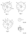
- Figures 3, 4 and 5 give examples of an asymmetrical arrangement of fuel exit openings 15 with respect to a symmetry plane A.
- the symmetry plane A is defined as a symmetry plane of an end surface 11 at the burner 10, for instance of a burner tile arranged at the end surface 11 of the burner 10. Such a symmetry plane A extends transverse to the end surface 11 of the burner 10 and at the same time extends through a central axis (not shown) of the burner 10.
- the fuel exit openings 15 may be asymmetrically arranged with respect to any plane transverse to the end surface 11 of the burner 10 and extending through a central axis (not shown) of said burner 10.
- the fuel exit openings 15 can be asymmetrically arranged, as illustrated in Fig. 4 .
- the capacity of the fuel exit openings may be asymmetrically distributed, as illustrated in Fig. 3 .
- Large capacity fuel exit openings 15a are asymmetrically distributed with respect to the symmetry plane A.
- the fuel openings 15, 15a are symmetrically arranged with respect to the symmetry plane A or to any other symmetry plane, only the capacity is asymmetrically arranged, resulting in an asymmetrical flame front.
- the fuel exit openings 15 are asymmetrically distributed with respect to the symmetry plane A, resulting in an asymmetrical flame front.
- the fuel exit openings 15 are asymmetrically distributed with respect to a central axis C such that adjacent fuel exit openings 15 are arranged at mutual different circumferential distances and/or radial distances with respect to the central axis C.
- the fuel exit openings 15, 15a are asymmetrically distributed and the capacity of the fuel exit openings is asymmetrically arranged with respect to the symmetry plane A or any other symmetry plane.
- Large capacity fuel exit openings 15a are asymmetrically distributed with respect to the symmetry plane A.
- the fuel exit openings 15, 15a are asymmetrically distributed with respect to the symmetry plane A, resulting in an asymmetrical flame front.
- radial distances between adjacent fuel exit openings 15, 15a and/or circumferential distances between adjacent fuel exit openings 15, 15a may vary.
- an asymmetrical flame front may be created by providing different exit angles and/or different dimensions and/or different shapes of the exit openings in an asymmetrical distribution with respect to the symmetry plane.
- the end part of the fuel supply channel 13 comprises a number of end tips 16 which are according to the invention asymmetrically arranged.
- the end tip 16 as shown in Fig. 6 , comprises the fuel exit opening 15. Fuel gas flows through the channel 13 in the direction of arrow B.
- the end tip 16 may be exchangeable, preferably during use of the furnace 2. Due to the exchangeability of the end tip 16, for example a normal capacity end tip 15 may be relatively easily replaced by a large capacity end tip.
- the end tip 16 may comprise different exit openings 15.
- the exit openings 15 may have different exit angles and/or different dimensions and/or different shapes. By providing an asymmetrical distribution of end tips with different characteristics of the exit openings, such as dimension, shape, exit angle, capacity, etc. an asymmetrical flame front may be created.
Landscapes
- Engineering & Computer Science (AREA)
- Chemical & Material Sciences (AREA)
- Combustion & Propulsion (AREA)
- Mechanical Engineering (AREA)
- General Engineering & Computer Science (AREA)
- Pre-Mixing And Non-Premixing Gas Burner (AREA)
- Furnace Details (AREA)
- Combustion Of Fluid Fuel (AREA)
- Gas Burners (AREA)
Claims (7)
- Brûleur pour un fourneau comprenant au moins un canal d'alimentation (12) pour alimenter en milieu oxydant et une pluralité de canaux d'alimentation en combustible périphériques (13), dans lequel le canal d'alimentation en milieu oxydant (12) et les canaux d'alimentation en combustible (13) ont des ouvertures de sortie (14, 15) agencées de manière adjacente entre elles au niveau d'une surface d'extrémité de brûleur (11) pour former, pendant l'utilisation suite à la réaction du combustible alimenté avec le milieu oxydant fourni, un front de flamme, caractérisé en ce que l'ouverture de sortie (14) du canal d'alimentation en milieu oxydant (12) et les ouvertures de sortie (15, 15a) des canaux d'alimentation en combustible (13) sont agencées de manière asymétrique par rapport à un plan quelconque agencé transversalement par rapport à une surface d'extrémité du brûleur et s'étendant à travers un axe central de brûleur (C), moyennant quoi la distribution des ouvertures de sortie de combustible et/ou la dimension des ouvertures de sortie de combustible et/ou de l'angle de sortie des ouvertures de sortie de combustible et/ou de la forme des ouvertures de sortie de combustible sont agencées de manière asymétrique par rapport à un plan quelconque, de sorte que pendant l'utilisation, on crée un front de flamme qui est asymétrique par rapport audit un plan quelconque.
- Brûleur selon la revendication 1, dans lequel le canal d'alimentation en combustible (13) comprend un embout (16) comprenant au moins une ouverture de sortie de combustible (15, 15a).
- Brûleur selon la revendication 2, dans lequel l'agencement d'au moins un embout (16) est différent des autres embouts du brûleur.
- Brûleur selon la revendication 2 ou 3, dans lequel l'embout (16) est échangeable.
- Brûleur selon l'une quelconque des revendications précédentes, dans lequel le brûleur est un brûleur Large Scale Vortex®.
- Fourneau (1) comprenant au moins un brûleur selon l'une quelconque des revendications 1 à 5.
- Fourneau (1) selon la revendication 6, dans lequel les brûleurs sont agencés dans une rangée sur une paroi d'une chambre de combustion (2) du fourneau (1).
Priority Applications (1)
| Application Number | Priority Date | Filing Date | Title |
|---|---|---|---|
| EP12701713.5A EP2665970B1 (fr) | 2011-01-21 | 2012-01-20 | Brûleur et fourneau le comprenant |
Applications Claiming Priority (3)
| Application Number | Priority Date | Filing Date | Title |
|---|---|---|---|
| EP11151640A EP2479492A1 (fr) | 2011-01-21 | 2011-01-21 | Brûleur, four |
| PCT/EP2012/050870 WO2012098229A2 (fr) | 2011-01-21 | 2012-01-20 | Brûleur et fourneau le comprenant |
| EP12701713.5A EP2665970B1 (fr) | 2011-01-21 | 2012-01-20 | Brûleur et fourneau le comprenant |
Publications (2)
| Publication Number | Publication Date |
|---|---|
| EP2665970A2 EP2665970A2 (fr) | 2013-11-27 |
| EP2665970B1 true EP2665970B1 (fr) | 2015-07-08 |
Family
ID=43877217
Family Applications (2)
| Application Number | Title | Priority Date | Filing Date |
|---|---|---|---|
| EP11151640A Withdrawn EP2479492A1 (fr) | 2011-01-21 | 2011-01-21 | Brûleur, four |
| EP12701713.5A Active EP2665970B1 (fr) | 2011-01-21 | 2012-01-20 | Brûleur et fourneau le comprenant |
Family Applications Before (1)
| Application Number | Title | Priority Date | Filing Date |
|---|---|---|---|
| EP11151640A Withdrawn EP2479492A1 (fr) | 2011-01-21 | 2011-01-21 | Brûleur, four |
Country Status (9)
| Country | Link |
|---|---|
| US (1) | US9410700B2 (fr) |
| EP (2) | EP2479492A1 (fr) |
| JP (1) | JP6039582B2 (fr) |
| KR (1) | KR20140016888A (fr) |
| CN (1) | CN103380328B (fr) |
| ES (1) | ES2544716T3 (fr) |
| HU (1) | HUE025335T2 (fr) |
| PT (1) | PT2665970E (fr) |
| WO (1) | WO2012098229A2 (fr) |
Families Citing this family (3)
| Publication number | Priority date | Publication date | Assignee | Title |
|---|---|---|---|---|
| US9360257B2 (en) * | 2014-02-28 | 2016-06-07 | Air Products And Chemicals, Inc. | Transient heating burner and method |
| CN105588117B (zh) * | 2014-04-17 | 2017-12-08 | 洪序明 | 加热面积大的压缩式燃烧炉 |
| JP2019045008A (ja) | 2017-08-30 | 2019-03-22 | 大陽日酸株式会社 | バーナ及びバーナを用いた加熱方法 |
Family Cites Families (17)
| Publication number | Priority date | Publication date | Assignee | Title |
|---|---|---|---|---|
| GB8720468D0 (en) * | 1987-08-29 | 1987-10-07 | Boc Group Plc | Flame treatment method |
| JP2683545B2 (ja) * | 1988-05-25 | 1997-12-03 | 東京瓦斯 株式会社 | 炉内燃焼方法 |
| FR2713312B1 (fr) * | 1993-11-30 | 1996-01-12 | Air Liquide | Brûleur oxycombustible agencé pour réduire la formation d'oxydes d'azote et particulièrement destiné aux fours de verrerie. |
| JP3052262B2 (ja) | 1994-08-04 | 2000-06-12 | 株式会社神戸製鋼所 | 燃焼炉とその低NOx燃焼方法 |
| ES2220965T3 (es) * | 1995-07-17 | 2004-12-16 | L'air Liquide, S.A. A Directoire Et Conseil De Surv. Pour L'etude Et L'exploitat. Procedes G. Claude | Proceso de combustion y aparato para el mismo con inyeccion separada de las corrientes de combustible y oxidante. |
| US5975886A (en) | 1996-11-25 | 1999-11-02 | L'air Liquide, Societe Anonyme Pour L'etude Et L'exploitation Des Procedes Georges Claude | Combustion process and apparatus therefore containing separate injection of fuel and oxidant streams |
| FR2782780B1 (fr) | 1998-09-02 | 2000-10-06 | Air Liquide | Procede de combustion pour bruler un combustible |
| US6544029B2 (en) | 2000-09-27 | 2003-04-08 | L'air Liquide - Societe' Anonyme A Directoire Et Conseil De Surveillance Pour L'etude Et L'exploitation Des Procedes Georges Claude | Methods and apparatus for combustion in high volatiles environments |
| US6773256B2 (en) * | 2002-02-05 | 2004-08-10 | Air Products And Chemicals, Inc. | Ultra low NOx burner for process heating |
| ATE338916T1 (de) * | 2002-01-31 | 2006-09-15 | Air Prod & Chem | Brenner für prozessheizung mit sehr niedrigem nox ausstoss |
| SE528808C2 (sv) | 2004-09-15 | 2007-02-20 | Aga Ab | Förfarande vid förbränning, jämte brännare |
| FR2880410B1 (fr) * | 2005-01-03 | 2007-03-16 | Air Liquide | Procede de combustion etagee produisant des flammes asymetriques |
| US7686611B2 (en) * | 2005-11-03 | 2010-03-30 | Air Products And Chemicals, Inc. | Flame straightening in a furnace |
| US8696348B2 (en) * | 2006-04-26 | 2014-04-15 | Air Products And Chemicals, Inc. | Ultra-low NOx burner assembly |
| US20080096146A1 (en) * | 2006-10-24 | 2008-04-24 | Xianming Jimmy Li | Low NOx staged fuel injection burner for creating plug flow |
| RU2474760C2 (ru) | 2008-08-29 | 2013-02-10 | Л'Эр Ликид Сосьете Аноним Пур Л'Этюд Э Л'Эксплуатасьон Де Проседе Жорж Клод | Способ генерирования горения посредством горелки в сборе и горелка в сборе |
| US8545213B2 (en) * | 2010-03-09 | 2013-10-01 | Air Products And Chemicals, Inc. | Reformer and method of operating the reformer |
-
2011
- 2011-01-21 EP EP11151640A patent/EP2479492A1/fr not_active Withdrawn
-
2012
- 2012-01-20 EP EP12701713.5A patent/EP2665970B1/fr active Active
- 2012-01-20 JP JP2013549829A patent/JP6039582B2/ja active Active
- 2012-01-20 US US13/980,444 patent/US9410700B2/en active Active
- 2012-01-20 ES ES12701713.5T patent/ES2544716T3/es active Active
- 2012-01-20 WO PCT/EP2012/050870 patent/WO2012098229A2/fr not_active Ceased
- 2012-01-20 KR KR1020137021538A patent/KR20140016888A/ko not_active Ceased
- 2012-01-20 CN CN201280006087.2A patent/CN103380328B/zh active Active
- 2012-01-20 PT PT127017135T patent/PT2665970E/pt unknown
- 2012-01-20 HU HUE12701713A patent/HUE025335T2/en unknown
Also Published As
| Publication number | Publication date |
|---|---|
| WO2012098229A2 (fr) | 2012-07-26 |
| JP2014508267A (ja) | 2014-04-03 |
| EP2665970A2 (fr) | 2013-11-27 |
| CN103380328A (zh) | 2013-10-30 |
| EP2479492A1 (fr) | 2012-07-25 |
| KR20140016888A (ko) | 2014-02-10 |
| US9410700B2 (en) | 2016-08-09 |
| CN103380328B (zh) | 2016-04-06 |
| US20140038116A1 (en) | 2014-02-06 |
| JP6039582B2 (ja) | 2016-12-07 |
| ES2544716T3 (es) | 2015-09-03 |
| PT2665970E (pt) | 2015-09-17 |
| WO2012098229A3 (fr) | 2012-12-13 |
| HUE025335T2 (en) | 2016-02-29 |
Similar Documents
| Publication | Publication Date | Title |
|---|---|---|
| US11156356B2 (en) | Fuel combustion system with a perforated reaction holder | |
| EP3106746B1 (fr) | Four à régénération comorenant un système de brûleur oxy-combustible sélectif boosté et procédé pour un four à régénération | |
| KR20180116400A (ko) | 버너, 퍼니스, 및 이를 이용하는 증기 분해 방법 | |
| KR20130130072A (ko) | 산소-연료 버너 장치 | |
| EP2665970B1 (fr) | Brûleur et fourneau le comprenant | |
| KR100563761B1 (ko) | 짝을 이룬 버너로 구획된 연소 시스템을 갖는 열분해 가열기 | |
| US9488383B2 (en) | Hermetically sealed gas heater and continuous heating furnace using hermetically sealed gas heater | |
| JP5472999B2 (ja) | ラジアントチューブバーナ | |
| RU2070687C1 (ru) | Горелка | |
| RU2775169C1 (ru) | Горелка для обжига керамических изделий и устройство для обжига керамических изделий | |
| FI125911B (en) | Low Nitrogen Oxide Gas Burner and Method for Combustion of Fuel Gas | |
| EP3638952B1 (fr) | Procédé de combustion de combustible gazeux ou liquide | |
| CN108458363A (zh) | 蓄热式燃烧器装置 | |
| KR20200037798A (ko) | 유동 협소부를 갖는 석탄 노즐 | |
| KR20180078364A (ko) | 파이어 히터 |
Legal Events
| Date | Code | Title | Description |
|---|---|---|---|
| PUAI | Public reference made under article 153(3) epc to a published international application that has entered the european phase |
Free format text: ORIGINAL CODE: 0009012 |
|
| 17P | Request for examination filed |
Effective date: 20130820 |
|
| AK | Designated contracting states |
Kind code of ref document: A2 Designated state(s): AL AT BE BG CH CY CZ DE DK EE ES FI FR GB GR HR HU IE IS IT LI LT LU LV MC MK MT NL NO PL PT RO RS SE SI SK SM TR |
|
| DAX | Request for extension of the european patent (deleted) | ||
| GRAP | Despatch of communication of intention to grant a patent |
Free format text: ORIGINAL CODE: EPIDOSNIGR1 |
|
| INTG | Intention to grant announced |
Effective date: 20150306 |
|
| GRAS | Grant fee paid |
Free format text: ORIGINAL CODE: EPIDOSNIGR3 |
|
| GRAA | (expected) grant |
Free format text: ORIGINAL CODE: 0009210 |
|
| AK | Designated contracting states |
Kind code of ref document: B1 Designated state(s): AL AT BE BG CH CY CZ DE DK EE ES FI FR GB GR HR HU IE IS IT LI LT LU LV MC MK MT NL NO PL PT RO RS SE SI SK SM TR |
|
| REG | Reference to a national code |
Ref country code: GB Ref legal event code: FG4D |
|
| REG | Reference to a national code |
Ref country code: AT Ref legal event code: REF Ref document number: 735706 Country of ref document: AT Kind code of ref document: T Effective date: 20150715 Ref country code: CH Ref legal event code: EP |
|
| REG | Reference to a national code |
Ref country code: IE Ref legal event code: FG4D |
|
| REG | Reference to a national code |
Ref country code: SE Ref legal event code: TRGR |
|
| REG | Reference to a national code |
Ref country code: DE Ref legal event code: R096 Ref document number: 602012008583 Country of ref document: DE |
|
| REG | Reference to a national code |
Ref country code: ES Ref legal event code: FG2A Ref document number: 2544716 Country of ref document: ES Kind code of ref document: T3 Effective date: 20150903 |
|
| REG | Reference to a national code |
Ref country code: PT Ref legal event code: SC4A Free format text: AVAILABILITY OF NATIONAL TRANSLATION Effective date: 20150805 |
|
| REG | Reference to a national code |
Ref country code: NO Ref legal event code: T2 Effective date: 20150708 |
|
| REG | Reference to a national code |
Ref country code: NL Ref legal event code: FP |
|
| REG | Reference to a national code |
Ref country code: LT Ref legal event code: MG4D |
|
| PG25 | Lapsed in a contracting state [announced via postgrant information from national office to epo] |
Ref country code: LT Free format text: LAPSE BECAUSE OF FAILURE TO SUBMIT A TRANSLATION OF THE DESCRIPTION OR TO PAY THE FEE WITHIN THE PRESCRIBED TIME-LIMIT Effective date: 20150708 Ref country code: GR Free format text: LAPSE BECAUSE OF FAILURE TO SUBMIT A TRANSLATION OF THE DESCRIPTION OR TO PAY THE FEE WITHIN THE PRESCRIBED TIME-LIMIT Effective date: 20151009 Ref country code: LV Free format text: LAPSE BECAUSE OF FAILURE TO SUBMIT A TRANSLATION OF THE DESCRIPTION OR TO PAY THE FEE WITHIN THE PRESCRIBED TIME-LIMIT Effective date: 20150708 |
|
| PGFP | Annual fee paid to national office [announced via postgrant information from national office to epo] |
Ref country code: FI Payment date: 20151222 Year of fee payment: 5 |
|
| REG | Reference to a national code |
Ref country code: FR Ref legal event code: PLFP Year of fee payment: 5 |
|
| PG25 | Lapsed in a contracting state [announced via postgrant information from national office to epo] |
Ref country code: PL Free format text: LAPSE BECAUSE OF FAILURE TO SUBMIT A TRANSLATION OF THE DESCRIPTION OR TO PAY THE FEE WITHIN THE PRESCRIBED TIME-LIMIT Effective date: 20150708 Ref country code: IS Free format text: LAPSE BECAUSE OF FAILURE TO SUBMIT A TRANSLATION OF THE DESCRIPTION OR TO PAY THE FEE WITHIN THE PRESCRIBED TIME-LIMIT Effective date: 20151108 Ref country code: RS Free format text: LAPSE BECAUSE OF FAILURE TO SUBMIT A TRANSLATION OF THE DESCRIPTION OR TO PAY THE FEE WITHIN THE PRESCRIBED TIME-LIMIT Effective date: 20150708 Ref country code: HR Free format text: LAPSE BECAUSE OF FAILURE TO SUBMIT A TRANSLATION OF THE DESCRIPTION OR TO PAY THE FEE WITHIN THE PRESCRIBED TIME-LIMIT Effective date: 20150708 |
|
| PGFP | Annual fee paid to national office [announced via postgrant information from national office to epo] |
Ref country code: CZ Payment date: 20151218 Year of fee payment: 5 Ref country code: PT Payment date: 20151217 Year of fee payment: 5 |
|
| REG | Reference to a national code |
Ref country code: HU Ref legal event code: AG4A Ref document number: E025335 Country of ref document: HU |
|
| REG | Reference to a national code |
Ref country code: DE Ref legal event code: R097 Ref document number: 602012008583 Country of ref document: DE |
|
| PG25 | Lapsed in a contracting state [announced via postgrant information from national office to epo] |
Ref country code: EE Free format text: LAPSE BECAUSE OF FAILURE TO SUBMIT A TRANSLATION OF THE DESCRIPTION OR TO PAY THE FEE WITHIN THE PRESCRIBED TIME-LIMIT Effective date: 20150708 Ref country code: SK Free format text: LAPSE BECAUSE OF FAILURE TO SUBMIT A TRANSLATION OF THE DESCRIPTION OR TO PAY THE FEE WITHIN THE PRESCRIBED TIME-LIMIT Effective date: 20150708 Ref country code: DK Free format text: LAPSE BECAUSE OF FAILURE TO SUBMIT A TRANSLATION OF THE DESCRIPTION OR TO PAY THE FEE WITHIN THE PRESCRIBED TIME-LIMIT Effective date: 20150708 |
|
| PLBE | No opposition filed within time limit |
Free format text: ORIGINAL CODE: 0009261 |
|
| STAA | Information on the status of an ep patent application or granted ep patent |
Free format text: STATUS: NO OPPOSITION FILED WITHIN TIME LIMIT |
|
| PG25 | Lapsed in a contracting state [announced via postgrant information from national office to epo] |
Ref country code: RO Free format text: LAPSE BECAUSE OF FAILURE TO SUBMIT A TRANSLATION OF THE DESCRIPTION OR TO PAY THE FEE WITHIN THE PRESCRIBED TIME-LIMIT Effective date: 20150708 |
|
| PGFP | Annual fee paid to national office [announced via postgrant information from national office to epo] |
Ref country code: SE Payment date: 20160128 Year of fee payment: 5 Ref country code: HU Payment date: 20160111 Year of fee payment: 5 |
|
| 26N | No opposition filed |
Effective date: 20160411 |
|
| PG25 | Lapsed in a contracting state [announced via postgrant information from national office to epo] |
Ref country code: LU Free format text: LAPSE BECAUSE OF FAILURE TO SUBMIT A TRANSLATION OF THE DESCRIPTION OR TO PAY THE FEE WITHIN THE PRESCRIBED TIME-LIMIT Effective date: 20160120 Ref country code: SI Free format text: LAPSE BECAUSE OF FAILURE TO SUBMIT A TRANSLATION OF THE DESCRIPTION OR TO PAY THE FEE WITHIN THE PRESCRIBED TIME-LIMIT Effective date: 20150708 |
|
| REG | Reference to a national code |
Ref country code: CH Ref legal event code: PL |
|
| PG25 | Lapsed in a contracting state [announced via postgrant information from national office to epo] |
Ref country code: MC Free format text: LAPSE BECAUSE OF FAILURE TO SUBMIT A TRANSLATION OF THE DESCRIPTION OR TO PAY THE FEE WITHIN THE PRESCRIBED TIME-LIMIT Effective date: 20150708 |
|
| PG25 | Lapsed in a contracting state [announced via postgrant information from national office to epo] |
Ref country code: CH Free format text: LAPSE BECAUSE OF NON-PAYMENT OF DUE FEES Effective date: 20160131 Ref country code: LI Free format text: LAPSE BECAUSE OF NON-PAYMENT OF DUE FEES Effective date: 20160131 |
|
| REG | Reference to a national code |
Ref country code: IE Ref legal event code: MM4A |
|
| REG | Reference to a national code |
Ref country code: FR Ref legal event code: PLFP Year of fee payment: 6 |
|
| PG25 | Lapsed in a contracting state [announced via postgrant information from national office to epo] |
Ref country code: IE Free format text: LAPSE BECAUSE OF NON-PAYMENT OF DUE FEES Effective date: 20160120 |
|
| REG | Reference to a national code |
Ref country code: AT Ref legal event code: UEP Ref document number: 735706 Country of ref document: AT Kind code of ref document: T Effective date: 20150708 |
|
| PG25 | Lapsed in a contracting state [announced via postgrant information from national office to epo] |
Ref country code: MT Free format text: LAPSE BECAUSE OF FAILURE TO SUBMIT A TRANSLATION OF THE DESCRIPTION OR TO PAY THE FEE WITHIN THE PRESCRIBED TIME-LIMIT Effective date: 20150708 |
|
| PG25 | Lapsed in a contracting state [announced via postgrant information from national office to epo] |
Ref country code: CZ Free format text: LAPSE BECAUSE OF NON-PAYMENT OF DUE FEES Effective date: 20170120 Ref country code: FI Free format text: LAPSE BECAUSE OF NON-PAYMENT OF DUE FEES Effective date: 20170120 |
|
| PG25 | Lapsed in a contracting state [announced via postgrant information from national office to epo] |
Ref country code: HU Free format text: LAPSE BECAUSE OF NON-PAYMENT OF DUE FEES Effective date: 20170121 Ref country code: SE Free format text: LAPSE BECAUSE OF NON-PAYMENT OF DUE FEES Effective date: 20170121 Ref country code: PT Free format text: LAPSE BECAUSE OF NON-PAYMENT OF DUE FEES Effective date: 20170720 |
|
| REG | Reference to a national code |
Ref country code: FR Ref legal event code: PLFP Year of fee payment: 7 |
|
| REG | Reference to a national code |
Ref country code: AT Ref legal event code: MM01 Ref document number: 735706 Country of ref document: AT Kind code of ref document: T Effective date: 20170120 |
|
| PG25 | Lapsed in a contracting state [announced via postgrant information from national office to epo] |
Ref country code: AT Free format text: LAPSE BECAUSE OF NON-PAYMENT OF DUE FEES Effective date: 20170120 Ref country code: CY Free format text: LAPSE BECAUSE OF FAILURE TO SUBMIT A TRANSLATION OF THE DESCRIPTION OR TO PAY THE FEE WITHIN THE PRESCRIBED TIME-LIMIT Effective date: 20150708 Ref country code: SM Free format text: LAPSE BECAUSE OF FAILURE TO SUBMIT A TRANSLATION OF THE DESCRIPTION OR TO PAY THE FEE WITHIN THE PRESCRIBED TIME-LIMIT Effective date: 20150708 |
|
| PG25 | Lapsed in a contracting state [announced via postgrant information from national office to epo] |
Ref country code: MK Free format text: LAPSE BECAUSE OF FAILURE TO SUBMIT A TRANSLATION OF THE DESCRIPTION OR TO PAY THE FEE WITHIN THE PRESCRIBED TIME-LIMIT Effective date: 20150708 Ref country code: MT Free format text: LAPSE BECAUSE OF FAILURE TO SUBMIT A TRANSLATION OF THE DESCRIPTION OR TO PAY THE FEE WITHIN THE PRESCRIBED TIME-LIMIT Effective date: 20160131 Ref country code: TR Free format text: LAPSE BECAUSE OF FAILURE TO SUBMIT A TRANSLATION OF THE DESCRIPTION OR TO PAY THE FEE WITHIN THE PRESCRIBED TIME-LIMIT Effective date: 20150708 |
|
| PG25 | Lapsed in a contracting state [announced via postgrant information from national office to epo] |
Ref country code: BG Free format text: LAPSE BECAUSE OF FAILURE TO SUBMIT A TRANSLATION OF THE DESCRIPTION OR TO PAY THE FEE WITHIN THE PRESCRIBED TIME-LIMIT Effective date: 20150708 |
|
| PG25 | Lapsed in a contracting state [announced via postgrant information from national office to epo] |
Ref country code: AL Free format text: LAPSE BECAUSE OF FAILURE TO SUBMIT A TRANSLATION OF THE DESCRIPTION OR TO PAY THE FEE WITHIN THE PRESCRIBED TIME-LIMIT Effective date: 20150708 |
|
| P01 | Opt-out of the competence of the unified patent court (upc) registered |
Effective date: 20230601 |
|
| PGFP | Annual fee paid to national office [announced via postgrant information from national office to epo] |
Ref country code: GB Payment date: 20251218 Year of fee payment: 15 |
|
| PGFP | Annual fee paid to national office [announced via postgrant information from national office to epo] |
Ref country code: NL Payment date: 20251225 Year of fee payment: 15 Ref country code: FR Payment date: 20251222 Year of fee payment: 15 |
|
| PGFP | Annual fee paid to national office [announced via postgrant information from national office to epo] |
Ref country code: ES Payment date: 20260206 Year of fee payment: 15 |
|
| PGFP | Annual fee paid to national office [announced via postgrant information from national office to epo] |
Ref country code: NO Payment date: 20260109 Year of fee payment: 15 Ref country code: DE Payment date: 20251216 Year of fee payment: 15 |
|
| PGFP | Annual fee paid to national office [announced via postgrant information from national office to epo] |
Ref country code: BE Payment date: 20260106 Year of fee payment: 15 Ref country code: IT Payment date: 20251230 Year of fee payment: 15 |