EP2665975B1 - Climatiseur et appareil de communication et procédé connexe - Google Patents
Climatiseur et appareil de communication et procédé connexe Download PDFInfo
- Publication number
- EP2665975B1 EP2665975B1 EP11856381.6A EP11856381A EP2665975B1 EP 2665975 B1 EP2665975 B1 EP 2665975B1 EP 11856381 A EP11856381 A EP 11856381A EP 2665975 B1 EP2665975 B1 EP 2665975B1
- Authority
- EP
- European Patent Office
- Prior art keywords
- signal
- communication
- unit
- outdoor unit
- wireless
- Prior art date
- Legal status (The legal status is an assumption and is not a legal conclusion. Google has not performed a legal analysis and makes no representation as to the accuracy of the status listed.)
- Active
Links
Images





Classifications
-
- F—MECHANICAL ENGINEERING; LIGHTING; HEATING; WEAPONS; BLASTING
- F24—HEATING; RANGES; VENTILATING
- F24F—AIR-CONDITIONING; AIR-HUMIDIFICATION; VENTILATION; USE OF AIR CURRENTS FOR SCREENING
- F24F11/00—Control or safety arrangements
- F24F11/30—Control or safety arrangements for purposes related to the operation of the system, e.g. for safety or monitoring
-
- F—MECHANICAL ENGINEERING; LIGHTING; HEATING; WEAPONS; BLASTING
- F25—REFRIGERATION OR COOLING; COMBINED HEATING AND REFRIGERATION SYSTEMS; HEAT PUMP SYSTEMS; MANUFACTURE OR STORAGE OF ICE; LIQUEFACTION SOLIDIFICATION OF GASES
- F25D—REFRIGERATORS; COLD ROOMS; ICE-BOXES; COOLING OR FREEZING APPARATUS NOT OTHERWISE PROVIDED FOR
- F25D29/00—Arrangement or mounting of control or safety devices
-
- F—MECHANICAL ENGINEERING; LIGHTING; HEATING; WEAPONS; BLASTING
- F24—HEATING; RANGES; VENTILATING
- F24F—AIR-CONDITIONING; AIR-HUMIDIFICATION; VENTILATION; USE OF AIR CURRENTS FOR SCREENING
- F24F1/00—Room units for air-conditioning, e.g. separate or self-contained units or units receiving primary air from a central station
- F24F1/0003—Room units for air-conditioning, e.g. separate or self-contained units or units receiving primary air from a central station characterised by a split arrangement, wherein parts of the air-conditioning system, e.g. evaporator and condenser, are in separately located units
-
- F—MECHANICAL ENGINEERING; LIGHTING; HEATING; WEAPONS; BLASTING
- F24—HEATING; RANGES; VENTILATING
- F24F—AIR-CONDITIONING; AIR-HUMIDIFICATION; VENTILATION; USE OF AIR CURRENTS FOR SCREENING
- F24F11/00—Control or safety arrangements
- F24F11/50—Control or safety arrangements characterised by user interfaces or communication
- F24F11/54—Control or safety arrangements characterised by user interfaces or communication using one central controller connected to several sub-controllers
-
- F—MECHANICAL ENGINEERING; LIGHTING; HEATING; WEAPONS; BLASTING
- F24—HEATING; RANGES; VENTILATING
- F24F—AIR-CONDITIONING; AIR-HUMIDIFICATION; VENTILATION; USE OF AIR CURRENTS FOR SCREENING
- F24F3/00—Air-conditioning systems in which conditioned primary air is supplied from one or more central stations to distributing units in the rooms or spaces where it may receive secondary treatment; Apparatus specially designed for such systems
- F24F3/06—Air-conditioning systems in which conditioned primary air is supplied from one or more central stations to distributing units in the rooms or spaces where it may receive secondary treatment; Apparatus specially designed for such systems characterised by the arrangements for the supply of heat-exchange fluid for the subsequent treatment of primary air in the room units
- F24F3/065—Air-conditioning systems in which conditioned primary air is supplied from one or more central stations to distributing units in the rooms or spaces where it may receive secondary treatment; Apparatus specially designed for such systems characterised by the arrangements for the supply of heat-exchange fluid for the subsequent treatment of primary air in the room units with a plurality of evaporators or condensers
-
- H—ELECTRICITY
- H04—ELECTRIC COMMUNICATION TECHNIQUE
- H04Q—SELECTING
- H04Q9/00—Arrangements in telecontrol or telemetry systems for selectively calling a substation from a main station, in which substation desired apparatus is selected for applying a control signal thereto or for obtaining measured values therefrom
- H04Q9/04—Arrangements for synchronous operation
-
- F—MECHANICAL ENGINEERING; LIGHTING; HEATING; WEAPONS; BLASTING
- F24—HEATING; RANGES; VENTILATING
- F24F—AIR-CONDITIONING; AIR-HUMIDIFICATION; VENTILATION; USE OF AIR CURRENTS FOR SCREENING
- F24F11/00—Control or safety arrangements
- F24F11/50—Control or safety arrangements characterised by user interfaces or communication
- F24F11/56—Remote control
-
- F—MECHANICAL ENGINEERING; LIGHTING; HEATING; WEAPONS; BLASTING
- F24—HEATING; RANGES; VENTILATING
- F24F—AIR-CONDITIONING; AIR-HUMIDIFICATION; VENTILATION; USE OF AIR CURRENTS FOR SCREENING
- F24F11/00—Control or safety arrangements
- F24F11/62—Control or safety arrangements characterised by the type of control or by internal processing, e.g. using fuzzy logic, adaptive control or estimation of values
- F24F11/63—Electronic processing
-
- F—MECHANICAL ENGINEERING; LIGHTING; HEATING; WEAPONS; BLASTING
- F25—REFRIGERATION OR COOLING; COMBINED HEATING AND REFRIGERATION SYSTEMS; HEAT PUMP SYSTEMS; MANUFACTURE OR STORAGE OF ICE; LIQUEFACTION SOLIDIFICATION OF GASES
- F25B—REFRIGERATION MACHINES, PLANTS OR SYSTEMS; COMBINED HEATING AND REFRIGERATION SYSTEMS; HEAT PUMP SYSTEMS
- F25B2313/00—Compression machines, plants or systems with reversible cycle not otherwise provided for
- F25B2313/023—Compression machines, plants or systems with reversible cycle not otherwise provided for using multiple indoor units
Definitions
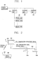
- an air conditioner as shown in FIG. 1 , includes an outdoor unit 200 to control distribution and circulation of a refrigerant, an indoor unit 100 connected to the outdoor unit to supply air into each indoor, and a central controller 300 connected to the outdoor unit 200 for center control of operations of the air conditioner.
- the indoor unit which receives the control command may forward the control command to the corresponding indoor unit without the communication apparatus 400 by using the pipe communication or dedicated line communication other than the wireless communication.
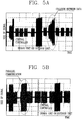
- a pair of first and second indoor units 100a and 100b may be connected to one outdoor unit 200, and the outdoor unit 200 may be provided with a communication apparatus 400.
- a central controller 300 may include a wireless communication unit 310.
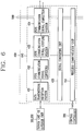
- FIG. 5A is a result view showing forms of first and second signals based on time when the first and second signals having the same frequency are transmitted via the same refrigerant pipe.
- FIG. 5A referring to FIG. 2 , it can be noticed that when the outdoor unit 200 transmits the second signal to the first indoor unit 100a and transmits the first signal having the same frequency to the second indoor unit 100b via the same refrigerant pipe 500, signal interference is caused between the first and second signals.
- the control command transmitted to the first and second indoor units 100a and 100b is unable to be completely restored, and accordingly the first and second indoor units 100a and 100b may erroneously operate.
- the first and second signals have the same frequency whose center frequency is about 132 KHz.
- FIG. 5B is a result view showing forms of first and second signals based on time when the first and second signals having frequency bands spaced from each other.
- the outdoor unit 200 transmits first and second signals simultaneously to the first and second indoor units 100a and 100b, signal interference is not caused between the first and second signals.
- the control command transmitted to the first and second indoor units 100a and 100b is able to be completely restored, and accordingly the first and second indoor units 100a and 100b can normally operate.
- the first and second signals have different frequencies whose center frequencies are 86 KHz and 132 KHz, respectively.
- the first and second frequencies belong to CENELEC A band (9-95 KHz) and CENELEC B band (95-140 KHz) of the European frequency standards.
- Ts denotes a sampling time of the first and second signals.
- the sampling time corresponds to a transmission time interval until transmission of the next control signal, with respect to the first and second signals. Therefore, the minimum bandwidth may be the double of an inverse number of the transmission time interval.
- first and second frequency bandwidths BW1, BW2 should be smaller than (f2 - f1)/2, in order for the first and second signals to have spaced frequency bands.
- the first signal should have a value of '0' at the second frequency band and the second signal should have a value of '0' at the first frequency band.
- the signal interference between the first and second signals may be avoided.
- the predetermined size which can avoid the interference between the first and second signals may depend on the characteristic of the system, for example, have a value below 30 dB.
- the outdoor unit 200 may transmit a control command as a first signal corresponding to a pipe communication signal to the first indoor unit 100a by employing a pipe communication method.
- the central controller 300 transmits the control command to the first indoor unit 100a, it may transmit the control command as a wireless signal to the second indoor unit 100b by employing a wireless communication method.
- the communication apparatus 400 installed in the second indoor unit 100b may convert the control command into a second signal corresponding to the pipe communication signal, and the second indoor unit 100b may transmit the second signal to the outdoor unit 200.
- the first and second signals may use frequency bands spaced from each other, no signal interference may be caused between the first and second signals even if transmitted through the same refrigerant pipe 500.
- first and second indoor units 100a and 100b and third and fourth indoor units 100c and 100d may be connected to a pair of first and second outdoor units 200a and 200b, respectively, with interposing a wall or floor therebetween, and the first and second outdoor units 200a and 200b and the second and fourth indoor units 100b and 100d may include a communication apparatus 400, respectively.
- a central controller 300 may include a wireless communication unit 310 and be installed inside.
- the first and second outdoor units 200a and 200b may transmit a control command as a first signal corresponding to a pipe communication signal to the first and third indoor units 100a and 100c, respectively, using a pipe communication method.
- the first outdoor unit 200a may convert the wireless signal into the second signal to transmit to the first indoor unit 100a.
- the first and second signals use the frequency bands spaced from each other, no signal interference may be caused even if transmitted through the same refrigerant pipe 500.
- the communication apparatus 400 for the air conditioner may be installed in the outdoor unit 200 or one of the indoor units 100 connected to the outdoor unit 200.
- the communication apparatus 400 may perform communication with the central controller 300 by a wireless communication method, and convert the second signal into a wireless signal corresponding to the second signal according to the wireless communication method or the wireless signal into the second signal according to a pipe communication method.
- the communication apparatus 400 may perform communication with the outdoor unit or the indoor unit using the first and second signals having frequency bands spaced from each other.
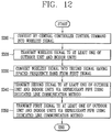
- the communication apparatus 400 may include a wireless communication unit 410 to communicate with the central controller 300 by the wireless communication method, a signal converting unit 420 to convert the second signal into a wireless signal corresponding to the second signal according to the wireless communication method or the wireless signal into the second signal according to the pipe communication method, and a pipe communication unit 430 to communicate with the outdoor unit or the indoor unit using the first and second signals by the pipe communication method.
- a wireless communication unit 410 to communicate with the central controller 300 by the wireless communication method
- a signal converting unit 420 to convert the second signal into a wireless signal corresponding to the second signal according to the wireless communication method or the wireless signal into the second signal according to the pipe communication method
- a pipe communication unit 430 to communicate with the outdoor unit or the indoor unit using the first and second signals by the pipe communication method.
- the wireless communication unit 410 may receive an operation command or control data for the outdoor unit 200 or the indoor unit 100 from the central controller 300 and forward the operation command or control data.
- the wireless communication unit 410 may employ any type of wireless communication method typically used.
- the wireless communication unit 410 may use wireless LAN, RF communication, Bluetooth, Infrared Data Association (IrDA) communication and the like.
- the pipe communication unit 430 may further include a pipe communication signal connection portion 434 to connect the pipe communication signal to the refrigerant pipe 500.
- the pipe communication signal connection portion 434 may include a magnetic core to form a predetermined inductance with respect to the pipe communication signal so as to enhance communication reliability.
- the outdoor unit 200 may transmit a control command as a first signal corresponding to a dedicated line communication signal to the second indoor unit 100b using a dedicated line communication method.
- the central controller 300 may convert the control command into a wireless signal by using the wireless communication unit 310, and transmit the wireless signal to the second indoor unit 100b.
- the communication apparatus 400 installed in the second indoor unit 100b may convert the wireless signal into a second signal as a dedicated line communication signal.
- the second indoor unit 100b may transmit the converted second signal to the first indoor unit 100a.
- the first and second signals use frequency bands spaced from each other, no signal interference may be caused between the first and second signals even if transmitted via the same dedicated line 600.
- first and second indoor units 100a and 100b and third and fourth indoor units 100c and 100d may be connected to a pair of first and second outdoor units 200a and 200b, respectively.
- the first and second outdoor unit 200a and 200b and the second and fourth indoor units 100b and 100d may include a communication apparatus 400, respectively.
- the central controller 300 may include a wireless communication unit 310 and be installed inside.
- the first outdoor unit 200a may transmit a control command to the second indoor unit 100b in form of (as) a first signal corresponding to a dedicated line communication signal using a dedicated line communication method.
- the central controller 300 may convert the control command into a wireless signal and transmit the wireless signal to the fourth indoor unit 100d the closest to the central controller 300 using a wireless communication method.
- the communication apparatus 400 installed in the fourth indoor unit 100d may convert the wireless signal into a second signal corresponding to a dedicated line communication signal.
- the fourth indoor unit 100d may then transmit the second signal as the dedicated line communication signal to the second outdoor unit 200b connected thereto via the dedicated line 600.
- the second outdoor unit 200b may convert the second signal into the wireless signal to transmit to the first outdoor unit 200a connected to the first indoor unit 100a.
- the first outdoor unit 200a may convert the wireless signal into the second signal to transmit to the first indoor unit 100a.
- the first and second signals use frequency bands spaced from each other, no signal interference may be caused between the first and second signals even if transmitted via the same dedicated line 600.
- the communication apparatus 400 may include a wireless communication unit 410 to communicate with the central controller 300 by the wireless communication method, a signal converting unit 421 to convert the second signal into a wireless signal corresponding to the second signal according to a wireless communication method or the wireless signal into the second signal according to a dedicated line communication method, and a dedicated line communication unit 440 to communicate with the outdoor unit 200 or the indoor unit 100 using the first and second signals by the dedicated line communication method.
- a dedicated line communication methods may include serial communication, parallel communication, LAN communication and the like, and generally RS-485 communication method is employed.
- the dedicated line communication unit 440 may include a data transmission/ reception portion 441 to receive or transmit data from or to the outdoor unit 200 or the indoor unit 100, and a dedicated line communication signal converter 442 to convert the data into the dedicated line communication signal or vice versa. Also, the dedicated line communication unit 440 may further include a dedicated line communication signal connection portion 444 to connect the dedicated line communication signal to the dedicated line. The dedicated line communication unit 440 may further include a dedicated line communication signal coupling portion 443. The dedicated line communication signal coupling portion 443 may be provided between the dedicated line communication signal converter 442 and the dedicated line communication signal connection portion 444, and filter the dedicated line communication signal.
- the data transmission/reception portion 441 may receive data from the outdoor unit 200 or the indoor unit 100 to transfer to the dedicated line communication signal converter 442, or transfer data received from the dedicated line communication signal converter 442 to the outdoor unit 200 or the indoor units 100.
- the dedicated line communication signal converter 442 may convert the data into the dedicated line communication signal or the dedicated line communication signal into the data to transfer to the data transmission/reception portion 441.
- the dedicated line communication signal coupling portion 443 may block an affection of external noise or serge, or filter the dedicate line communication signal.
- the dedicated line communication signal connection portion 444 may include a matching element to connect the dedicated line communication signal to the dedicated line.
- a communication method for the air conditioner via the communication apparatus may include converting by the central controller a control command into a wireless signal (S110), transmitting the wireless signal corresponding to the second signal to at least one of the indoor units and the outdoor unit (S120), converting the wireless signal corresponding to the second signal into the second signal corresponding to a pipe communication signal, which has a frequency band spaced from that of the first signal (S130), transmitting the second signal as the pipe communication signal to at least one of the outdoor unit and the indoor units via the refrigerant pipe (S140), and transmitting the first signal as the pipe communication signal to at least one of the outdoor unit and the indoor units via the refrig
- the corresponding outdoor unit or indoor unit receiving the control command may operate based on the control command.
- the wireless communication method may be at least one of common wireless communication methods, such as wireless LAN, RF communication, Bluetooth, IrDA communication and the like.
- FIGS. 2 to 4 and FIG. 6 show the configuration of the apparatus according to this specification.
- the pair of first and second indoor units 100a and 100b may be connected to the one outdoor unit 200, and the outdoor unit 200 may include the communication apparatus 400.
- the central controller 300 may include the wireless communication unit 310.
- the wireless communication unit 310 may convert a control command into a wireless signal (S110), and the central controller 300 may transmit the control command to the outdoor unit 200 using a wireless communication method (S 120).
- the outdoor unit 200 may convert the control command into a second signal as a pipe communication signal having a frequency band spaced from that of a first signal (S130), and transmit the converted second signal as the pipe communication signal to the first indoor unit 100a via the refrigerant pipe 500 (S140).
- the outdoor unit 200 may transmit the first signal as the pipe communication signal to the second indoor unit 100b via the refrigerant pipe 500 (S150).
- the control command received by the communication apparatus 400 may be converted into a second signal as a pipe communication signal (S130). Afterwards, the second indoor unit 100b may transmit the converted second signal, which has a frequency band spaced from that of a first signal, to the outdoor unit 200 via the refrigerant pipe 500 using the pipe communication method (S140). The outdoor unit 200 may transmit the first signal to the first indoor unit 100a via the refrigerant pipe 500 using a pipe communication method (S150).
- first and second indoor units 100a and 100b and third and fourth indoor units and 100d may be connected to a pair of first and second outdoor units 200a and 200b with interposing a wall or floor therebetween, and the outdoor units 200a and 200b and the second and fourth indoor units 100b and 100d may include a communication apparatus 400, respectively.
- a central controller 300 may include a wireless communication unit 310 and be installed inside. For example, for transmitting a control command to the first indoor unit 100a, the central controller 300 may convert the control command into a wireless signal and transmit the wireless signal to the fourth indoor unit 100d located the closest to the central controller 300 using a wireless communication method (S110, S120).
- the communication apparatus 400 installed in the fourth indoor unit 100d may convert the wireless signal into a second signal as a pipe communication signal (S130).
- the fourth indoor unit 100d may transmit the converted second signal, which has a frequency band spaced from that of a first signal, to the second outdoor unit 200b via the refrigerant pipe 500 using the pipe communication method (S140).
- the second outdoor unit 200b may transmit the first signal to the third indoor unit 100c via the refrigerant pipe 500 using a pipe communication method (S150).
- a communication method for the air conditioner via a communication apparatus performing communication using a second signal may include converting a control command into a wireless signal (S210), transmitting the wireless signal corresponding to the second signal to the outdoor unit (S220), converting the wireless signal corresponding to the second signal into the second signal, which has a frequency band spaced from that of the first signal (S230), transmitting the converted second signal from the outdoor unit to at least one of the indoor units via the refrigerant pipe using the pipe communication method (S240), and transmitting the first signal from the outdoor unit to at least one of the indoor units via the refrigerant pipe using a pipe communication method (S250).
- the outdoor unit 200b may convert the second signal into the wireless signal to transmit to the first outdoor unit 200a connected to the first indoor unit 100a (S210, S220).
- the first outdoor unit 200a may convert the wireless signal corresponding to the second signal into the second signal, which has a frequency band spaced from that of the first signal (S230).
- the first output unit 200a may transmit the converted second signal to the first indoor unit 100a via the refrigerant pipe 500 using the pipe communication method (S240), and transmit the first signal to the second indoor unit 100b via the refrigerant pipe 500 using the pipe communication method (S250).
- a communication method for the air conditioner via the communication apparatus may include converting by the central controller a control command into a wireless signal (S310), transmitting a wireless signal corresponding to the second signal to at least one of the indoor units and the outdoor unit (S320), converting the wireless signal corresponding to the second signal into the second signal as a dedicated line communication signal, which has a frequency band spaced from that of the first signal (S330), transmitting the converted second signal to at least one of the outdoor unit and the indoor units via the dedicated line using the dedicated line communication method (S340), and transmitting the first signal to at least one of the outdoor unit and the indoor units via a dedicated line using a dedicated line using a dedicated
- the corresponding outdoor unit or indoor unit which receives the control command may operate based on the control command.
- the wireless communication method may be at least one of wireless LAN, RF communication, Bluetooth, Infrared Data Association (IrDA) communication and the like.
- examples of the dedicated line communication methods may include serial communication, parallel communication, LAN communication and the like, and generally RS-485 communication method is employed.
- FIGS. 7 to 9 show the configuration of an apparatus according to this specification.
- a pair of first and second indoor units 100a and 100b may be connected to one outdoor unit 200 via a refrigerant pipe 500, and the outdoor unit 200 and the indoor units 100a and 100b may transmit and receive data via a dedicated line 600.
- a central controller 300 may include a wireless communication unit 310 and be installed adjacent to the second indoor unit 100b. For example, for transmitting a control command to the first indoor unit 100a, the central controller 300 may convert the control command into a wireless signal by the wireless communication unit 310 to transmit to the second indoor unit 100b (S310, S320).
- a communication apparatus 400 installed in the second indoor unit 100b may convert the wireless signal into a second signal as a dedicated line communication signal (S330).
- the second indoor unit 100b may transmit the converted second signal, which has a frequency band spaced from that of a first signal, to the outdoor unit 200 via the dedicated line 600 using the dedicated line communication method (S340).
- the outdoor unit 200 may transmit the first signal to the first indoor unit 100a via the dedicated line 600 using a dedicated line communication method (S350).
- first and second indoor units 100a and 100b and third and fourth indoor units 100c and 100d may be connected to a pair of first and second outdoor units 200a and 200b, respectively.
- the first and second outdoor units 200a and 200b and the second and fourth indoor units 100b and 100d may include a communication apparatus 400, respectively.
- a central controller 300 may include a wireless communication unit 310 and be installed inside. For example, for transmitting a control command to the indoor unit 100a, the central controller 300 may convert the control command into a wireless signal and transmit the wireless signal to the indoor unit 100d the closest to the central controller 300 using a wireless communication method (S310, S320).
- the communication apparatus 400 installed in the fourth indoor unit 100d may receive the wireless signal and convert the wireless signal into a second signal as a dedicated line communication signal (S330).
- the fourth indoor unit 100d may transmit the converted second signal, which has a frequency band spaced from that of the first signal, to the second outdoor unit 200b via the dedicated line 600 using the dedicated line communication method (S340).
- the second outdoor unit 200b may transmit the first signal to the third indoor unit 100c via the dedicated line 600 using the dedicated line communication method (S350).
- a communication method for the air conditioner via a communication apparatus performing communication using a second signal may include converting a control command into a wireless signal (S410), transmitting the wireless signal corresponding to the second signal to the outdoor unit (S420), converting the wireless signal corresponding to the second signal into the second signal, which has a frequency band spaced from that of the first signal (S430), transmitting the converted second signal from the outdoor unit to at least one of the indoor units via a dedicated line using a dedicated line communication method (S440), and transmitting the first signal from the outdoor unit to at least one of the indoor units via the dedicated line 600 using the dedicated line communication method (S450).
- the outdoor unit 200b may convert the second signal into a wireless signal to transmit to the first outdoor unit 200a connected to the first indoor unit 100a (S410, S420).
- the first outdoor unit 200a may convert the wireless signal corresponding to the second signal into the second signal, which has a frequency band spaced from that of the first signal (S430).
- the first outdoor unit 200a may transmit the converted second signal to the first indoor unit 100a via the dedicated line 600 using the dedicated line communication method (S440).
- the first outdoor unit 200a may transmit the first signal to the second indoor unit 100b via the dedicated line 600 using the dedicated line communication method (S450).
- the foregoing exemplary embodiments have employed the pipe communication method or the dedicated line communication method in addition to the wireless communication method.
- the present disclosure may not be limited to those methods.
- other wired or wireless communication methods such as a power line communication method and the like may also be employed.
- the outdoor unit or indoor unit may perform communication with the central controller using a plurality of communication methods including a wireless communication method and a dedicated line communication method, thereby reducing limitations due to an installation environment, which results in an increase in efficiency of a system operation.
Landscapes
- Engineering & Computer Science (AREA)
- General Engineering & Computer Science (AREA)
- Chemical & Material Sciences (AREA)
- Combustion & Propulsion (AREA)
- Mechanical Engineering (AREA)
- Physics & Mathematics (AREA)
- Human Computer Interaction (AREA)
- Signal Processing (AREA)
- Thermal Sciences (AREA)
- Computer Networks & Wireless Communication (AREA)
- Fuzzy Systems (AREA)
- Mathematical Physics (AREA)
- Air Conditioning Control Device (AREA)
Claims (6)
- Climatiseur comprenant un dispositif de communication (400),
une pluralité d'unités intérieures pour effectuer une climatisation d'air, au moins une unité extérieure (200) reliée aux unités intérieures (100) par une conduite de réfrigérant (500), le dispositif de communication étant prévu pour entraîner l'unité extérieure au moyen d'un premier signal, et un contrôleur central (300) pour commander le fonctionnement de l'unité extérieure (200) et des unités intérieures (100) au moyen d'un deuxième signal,
où le dispositif de communication (400) est monté dans l'unité extérieure (200) ou une des unités intérieures (100) reliées à l'unité extérieure (200) pour établir une communication avec le contrôleur central (300) au moyen d'un procédé de communication sans fil,
où le dispositif de communication (400) est prévu pour convertir le deuxième signal en un signal radio correspondant au deuxième signal conformément à un procédé de communication sans fil, ou le signal radio en deuxième signal conformément à un procédé de communication défini,
où le dispositif de communication (400) est prévu pour communiquer avec l'unité extérieure (200) ou l'unité intérieure (100) au moyen du premier et du deuxième signaux ayant des bandes de fréquence espacées l'une de l'autre,
où le dispositif de communication est prévu pour permettre une communication entre les unités extérieures (200) au moyen du procédé de communication sans fil,
où le dispositif de communication (400) est prévu dans l'unité extérieure (200) ou l'unité intérieure (100) la plus proche du contrôleur central, et
où le contrôleur central (300) est prévu pour transmettre le signal radio à l'unité extérieure (200) ou à l'unité intérieure (100) la plus proche de lui, ou à le recevoir de celle-ci. - Dispositif selon la revendication 1, où le dispositif de communication comprend :une unité de communication sans fil (410) pour établir une communication avec le contrôleur central (300) au moyen d'un procédé de communication sans fil ;une unité de conversion de signal pour convertir le deuxième signal en un signal radio correspondant au deuxième signal conformément au procédé de communication sans fil, ou le signal radio en deuxième signal conformément à un procédé de communication défini ; etune unité de communication pour communiquer avec l'unité extérieure (200) ou l'unité intérieure (100) au moyen du premier et du deuxième signaux conformément au procédé de communication défini.
- Dispositif selon la revendication 2, où l'unité de communication est une unité de communication de conduite (430) pour établir une communication au moyen du premier et du deuxième signaux conformément à un procédé de communication de conduite, ladite unité de communication de conduite (430) comprenant :une section de transmission/de réception de données (431) pour recevoir des données de l'unité extérieure ou de l'unité intérieure ou les transmettre à celle-ci ; etun convertisseur de signal de communication de conduite (432) pour convertir les données en signal de communication de conduite, ou le signal de communication de conduite en données.
- Dispositif selon la revendication 3, où l'unité de communication de conduite (430) comprend en outre :une section de connexion de signal de communication de conduite (434) pour connecter le signal de communication de conduite à la conduite de réfrigérant (500) ; etune section de couplage de signal de communication de conduite (433) disposée entre le convertisseur de signal de communication de conduite (432) et la section de connexion de signal de communication de conduite (434) pour filtrer le signal de communication de conduite, supprimer les bruits et protéger contre les surtensions.
- Dispositif selon la revendication 4, où l'unité de communication est une unité de communication de ligne dédiée pour l'établissement d'une communication au moyen du premier et du deuxième signaux conformément à un procédé de communication de ligne dédiée.
- Procédé de communication pour un climatiseur exécuté par un dispositif de communication (400), ledit climatiseur comprenant une pluralité d'unités intérieures (100) pour effectuer une climatisation d'air, au moins une unité extérieure (200) reliée aux unités intérieures (100) par une conduite de réfrigérant (500) pour entraîner les unités intérieures (100) au moyen d'un premier signal, un contrôleur central (300) pour commander le fonctionnement de l'unité extérieure (200) et des unités intérieures (100) au moyen d'un deuxième signal, et le dispositif de communication (400) pour établir une communication avec le contrôleur central (300), ledit procédé comprenant :la conversion par le contrôleur central (300) d'une instruction de commande en un signal radio ;la transmission du signal radio correspondant au deuxième signal à au moins une unité entre l'unité extérieure (200) et les unités intérieures (100) ;la réception du signal radio correspondant au deuxième signal à convertir en deuxième signal, ledit deuxième signal ayant une bande de fréquence espacée de celle du premier signal ;la transmission du deuxième signal à au moins une unité entre l'unité extérieure (200) et les unités intérieures (100) ; etla transmission du premier signal à au moins une unité entre l'unité extérieure (200) et les unités intérieures (100) ; etoù le dispositif de communication (400) est prévu pour permettre une communication entre les unités extérieures (200) au moyen du procédé de communication sans fil,où le dispositif de communication est prévu dans l'unité extérieure (200) ou l'unité intérieure (100) la plus proche du contrôleur central (300), etoù le contrôleur central (300) est prévu pour transmettre le signal radio à une unité extérieure (200) ou une unité intérieure (100) la plus proche de lui, ou à le recevoir de celle-ci.
Applications Claiming Priority (2)
| Application Number | Priority Date | Filing Date | Title |
|---|---|---|---|
| KR1020110006536A KR20120085110A (ko) | 2011-01-21 | 2011-01-21 | 공기 조화기와, 이의 통신 장치 및 통신 방법 |
| PCT/KR2011/009536 WO2012099333A2 (fr) | 2011-01-21 | 2011-12-12 | Climatiseur et appareil de communication et procédé connexe |
Publications (3)
| Publication Number | Publication Date |
|---|---|
| EP2665975A2 EP2665975A2 (fr) | 2013-11-27 |
| EP2665975A4 EP2665975A4 (fr) | 2018-07-11 |
| EP2665975B1 true EP2665975B1 (fr) | 2020-05-06 |
Family
ID=46516190
Family Applications (1)
| Application Number | Title | Priority Date | Filing Date |
|---|---|---|---|
| EP11856381.6A Active EP2665975B1 (fr) | 2011-01-21 | 2011-12-12 | Climatiseur et appareil de communication et procédé connexe |
Country Status (4)
| Country | Link |
|---|---|
| US (1) | US20130298576A1 (fr) |
| EP (1) | EP2665975B1 (fr) |
| KR (1) | KR20120085110A (fr) |
| WO (1) | WO2012099333A2 (fr) |
Families Citing this family (7)
| Publication number | Priority date | Publication date | Assignee | Title |
|---|---|---|---|---|
| JP6215084B2 (ja) * | 2014-02-25 | 2017-10-18 | 三菱重工サーマルシステムズ株式会社 | 空調システム |
| KR101970666B1 (ko) * | 2016-06-20 | 2019-04-22 | 엘지전자 주식회사 | 공기조화기 및 이의 통신방법 |
| KR101908306B1 (ko) * | 2017-01-05 | 2018-10-16 | 엘지전자 주식회사 | 공기조화기 및 그 제어방법 |
| KR102366020B1 (ko) * | 2017-03-14 | 2022-02-21 | 엘지전자 주식회사 | 공기조화기 |
| KR102457214B1 (ko) * | 2018-06-15 | 2022-10-21 | 삼성전자주식회사 | 공기 조화기 및 그 배관 통신 방법 |
| CN113483462B (zh) * | 2021-04-30 | 2022-12-16 | 佛山市顺德区美的电子科技有限公司 | 空调器及其基于电力线通讯的数据传输方法和存储介质 |
| JP2024049710A (ja) * | 2022-09-29 | 2024-04-10 | 三菱重工サーマルシステムズ株式会社 | 空気調和システム、空気調和システムの制御方法 |
Family Cites Families (20)
| Publication number | Priority date | Publication date | Assignee | Title |
|---|---|---|---|---|
| JP2799809B2 (ja) * | 1993-02-16 | 1998-09-21 | 株式会社日立製作所 | 空調管理システム |
| JPH09210433A (ja) * | 1996-02-05 | 1997-08-12 | Hitachi Ltd | 多室空気調和機用操作装置及び操作表示方法 |
| JP2001091026A (ja) * | 1999-09-27 | 2001-04-06 | Matsushita Electric Ind Co Ltd | 空気調和装置 |
| US6978627B2 (en) * | 2002-01-31 | 2005-12-27 | Mitsubishi Denki Kabushiki Kaisha | Air conditioner control system, central remote controller, and facility controller |
| JP2004028384A (ja) * | 2002-06-24 | 2004-01-29 | Hitachi Ltd | 空気調和機システム |
| JP4129594B2 (ja) * | 2003-04-15 | 2008-08-06 | 株式会社日立製作所 | 空調システム |
| KR100550556B1 (ko) * | 2003-11-11 | 2006-02-10 | 엘지전자 주식회사 | 에어컨의 중앙제어 시스템 및 그 동작방법 |
| JP2005164219A (ja) * | 2003-11-14 | 2005-06-23 | Mitsubishi Electric Corp | 空気調和機器および信号伝送方法 |
| JP3856035B2 (ja) * | 2004-02-24 | 2006-12-13 | ダイキン工業株式会社 | 空調監視制御システム |
| EP2239520B1 (fr) * | 2004-03-09 | 2011-11-16 | Mitsubishi Denki Kabushiki Kaisha | Équipement de climatisation et procédé de transmission pour signal de celui-ci |
| KR100613508B1 (ko) * | 2004-03-22 | 2006-08-17 | 엘지전자 주식회사 | 에어컨의 중앙제어 시스템 및 그 동작방법 |
| KR100700536B1 (ko) * | 2004-10-29 | 2007-03-28 | 엘지전자 주식회사 | 멀티형 공기조화기의 통신 시스템 |
| KR100747579B1 (ko) * | 2005-04-28 | 2007-08-08 | 엘지전자 주식회사 | 공조 시스템 및 그 제어방법 |
| JP4973345B2 (ja) * | 2007-07-05 | 2012-07-11 | ダイキン工業株式会社 | 冷媒系統検出方法、冷媒系統検出システム、および、冷媒系統検出プログラム |
| KR20090044776A (ko) * | 2007-11-01 | 2009-05-07 | 엘지전자 주식회사 | 공기조화기 시스템 |
| WO2010109627A1 (fr) * | 2009-03-26 | 2010-09-30 | 三菱電機株式会社 | Système de transport d'informations pour dispositif de réfrigération/conditionnement d'air |
| KR20100123486A (ko) * | 2009-05-15 | 2010-11-24 | 엘지전자 주식회사 | 공기조화기 및 그 제어방법 |
| US8640970B2 (en) * | 2009-05-27 | 2014-02-04 | Direct Success, Llc | Air quality control system |
| JP5036793B2 (ja) * | 2009-11-27 | 2012-09-26 | 三菱電機株式会社 | 空気調和機の制御装置 |
| US8290628B2 (en) * | 2010-07-23 | 2012-10-16 | Lg Electronics Inc. | Air conditioner and method for controlling the same |
-
2011
- 2011-01-21 KR KR1020110006536A patent/KR20120085110A/ko not_active Ceased
- 2011-12-12 US US13/980,785 patent/US20130298576A1/en not_active Abandoned
- 2011-12-12 EP EP11856381.6A patent/EP2665975B1/fr active Active
- 2011-12-12 WO PCT/KR2011/009536 patent/WO2012099333A2/fr not_active Ceased
Non-Patent Citations (1)
| Title |
|---|
| None * |
Also Published As
| Publication number | Publication date |
|---|---|
| US20130298576A1 (en) | 2013-11-14 |
| KR20120085110A (ko) | 2012-07-31 |
| EP2665975A4 (fr) | 2018-07-11 |
| WO2012099333A3 (fr) | 2012-09-13 |
| EP2665975A2 (fr) | 2013-11-27 |
| WO2012099333A2 (fr) | 2012-07-26 |
Similar Documents
| Publication | Publication Date | Title |
|---|---|---|
| US8781634B2 (en) | Air conditioning system and communication method thereof | |
| US20130298576A1 (en) | Air conditioner and communication apparatus and method thereof | |
| CN100532981C (zh) | 集中多个区域的空调系统 | |
| KR101229361B1 (ko) | 배관 통신 장치, 이를 포함한 공기 조화기 및 이의 배관 통신 방법 | |
| US9049038B2 (en) | Method of associating or re-associating devices in a control network | |
| CN104613591B (zh) | 一种空调无线组网方法 | |
| EP3851753B1 (fr) | Dispositif de réglage d'adresse et système de climatisation | |
| KR101257080B1 (ko) | 공기 조화기와, 이의 통신 장치 및 통신 방법 | |
| US20250102181A1 (en) | Air conditioning-related equipment and air conditioning system | |
| CN104121660A (zh) | 集pc、手机app控制的中央空调控制系统 | |
| CN111147612B (zh) | 一种基于位置信息的风机群控地址自动分配方法 | |
| KR101240272B1 (ko) | 공기 조화기 및 이의 통신 방법 | |
| CN114629938B (zh) | 一种中央吸油烟机系统及通讯方法 | |
| EP4203624A1 (fr) | Commande d'éclairage | |
| KR101214490B1 (ko) | 공기 조화기 및 이의 배관 통신 방법 | |
| KR101557053B1 (ko) | Rf 무선 네트워크를 이용한 냉난방 시스템 및 냉난방 시스템을 구성하는 유닛에 대한 아이디 부여방법 | |
| KR100529949B1 (ko) | 에어컨의 중앙제어 시스템 및 그 동작방법 | |
| JP3835320B2 (ja) | 換気量調整装置及び換気システム | |
| JP4592718B2 (ja) | ネットワーク識別id設定方法、通信ネットワークシステム | |
| KR101842542B1 (ko) | 가정용 냉난방장치 통합 관리 서버 | |
| KR101190099B1 (ko) | 오에프디엠 방식의 전력선 통신을 이용한 냉난방시스템 | |
| CN121993851A (zh) | 多联机空调系统、控制方法、存储介质及控制器 | |
| KR200416479Y1 (ko) | 스피커의 자동 고장 진단시스템 | |
| KR101398161B1 (ko) | 원격 제어를 위한 실내기 및 실외기를 가지는 멀티 에어컨 시스템 | |
| CN107635328A (zh) | 灯控器及双通道网络通讯系统 |
Legal Events
| Date | Code | Title | Description |
|---|---|---|---|
| PUAI | Public reference made under article 153(3) epc to a published international application that has entered the european phase |
Free format text: ORIGINAL CODE: 0009012 |
|
| 17P | Request for examination filed |
Effective date: 20130814 |
|
| AK | Designated contracting states |
Kind code of ref document: A2 Designated state(s): AL AT BE BG CH CY CZ DE DK EE ES FI FR GB GR HR HU IE IS IT LI LT LU LV MC MK MT NL NO PL PT RO RS SE SI SK SM TR |
|
| DAX | Request for extension of the european patent (deleted) | ||
| REG | Reference to a national code |
Ref country code: DE Ref legal event code: R079 Ref document number: 602011066778 Country of ref document: DE Free format text: PREVIOUS MAIN CLASS: F24F0011020000 Ipc: F24F0011000000 |
|
| A4 | Supplementary search report drawn up and despatched |
Effective date: 20180612 |
|
| RIC1 | Information provided on ipc code assigned before grant |
Ipc: H04Q 9/04 20060101ALI20180606BHEP Ipc: F24F 11/00 20060101AFI20180606BHEP |
|
| STAA | Information on the status of an ep patent application or granted ep patent |
Free format text: STATUS: EXAMINATION IS IN PROGRESS |
|
| 17Q | First examination report despatched |
Effective date: 20190208 |
|
| GRAP | Despatch of communication of intention to grant a patent |
Free format text: ORIGINAL CODE: EPIDOSNIGR1 |
|
| STAA | Information on the status of an ep patent application or granted ep patent |
Free format text: STATUS: GRANT OF PATENT IS INTENDED |
|
| INTG | Intention to grant announced |
Effective date: 20191120 |
|
| GRAS | Grant fee paid |
Free format text: ORIGINAL CODE: EPIDOSNIGR3 |
|
| GRAA | (expected) grant |
Free format text: ORIGINAL CODE: 0009210 |
|
| STAA | Information on the status of an ep patent application or granted ep patent |
Free format text: STATUS: THE PATENT HAS BEEN GRANTED |
|
| AK | Designated contracting states |
Kind code of ref document: B1 Designated state(s): AL AT BE BG CH CY CZ DE DK EE ES FI FR GB GR HR HU IE IS IT LI LT LU LV MC MK MT NL NO PL PT RO RS SE SI SK SM TR |
|
| REG | Reference to a national code |
Ref country code: GB Ref legal event code: FG4D |
|
| REG | Reference to a national code |
Ref country code: AT Ref legal event code: REF Ref document number: 1267397 Country of ref document: AT Kind code of ref document: T Effective date: 20200515 Ref country code: CH Ref legal event code: EP |
|
| REG | Reference to a national code |
Ref country code: IE Ref legal event code: FG4D |
|
| REG | Reference to a national code |
Ref country code: DE Ref legal event code: R096 Ref document number: 602011066778 Country of ref document: DE |
|
| REG | Reference to a national code |
Ref country code: LT Ref legal event code: MG4D |
|
| REG | Reference to a national code |
Ref country code: NL Ref legal event code: MP Effective date: 20200506 |
|
| PG25 | Lapsed in a contracting state [announced via postgrant information from national office to epo] |
Ref country code: LT Free format text: LAPSE BECAUSE OF FAILURE TO SUBMIT A TRANSLATION OF THE DESCRIPTION OR TO PAY THE FEE WITHIN THE PRESCRIBED TIME-LIMIT Effective date: 20200506 Ref country code: IS Free format text: LAPSE BECAUSE OF FAILURE TO SUBMIT A TRANSLATION OF THE DESCRIPTION OR TO PAY THE FEE WITHIN THE PRESCRIBED TIME-LIMIT Effective date: 20200906 Ref country code: SE Free format text: LAPSE BECAUSE OF FAILURE TO SUBMIT A TRANSLATION OF THE DESCRIPTION OR TO PAY THE FEE WITHIN THE PRESCRIBED TIME-LIMIT Effective date: 20200506 Ref country code: PT Free format text: LAPSE BECAUSE OF FAILURE TO SUBMIT A TRANSLATION OF THE DESCRIPTION OR TO PAY THE FEE WITHIN THE PRESCRIBED TIME-LIMIT Effective date: 20200907 Ref country code: GR Free format text: LAPSE BECAUSE OF FAILURE TO SUBMIT A TRANSLATION OF THE DESCRIPTION OR TO PAY THE FEE WITHIN THE PRESCRIBED TIME-LIMIT Effective date: 20200807 Ref country code: NO Free format text: LAPSE BECAUSE OF FAILURE TO SUBMIT A TRANSLATION OF THE DESCRIPTION OR TO PAY THE FEE WITHIN THE PRESCRIBED TIME-LIMIT Effective date: 20200806 Ref country code: FI Free format text: LAPSE BECAUSE OF FAILURE TO SUBMIT A TRANSLATION OF THE DESCRIPTION OR TO PAY THE FEE WITHIN THE PRESCRIBED TIME-LIMIT Effective date: 20200506 |
|
| PG25 | Lapsed in a contracting state [announced via postgrant information from national office to epo] |
Ref country code: RS Free format text: LAPSE BECAUSE OF FAILURE TO SUBMIT A TRANSLATION OF THE DESCRIPTION OR TO PAY THE FEE WITHIN THE PRESCRIBED TIME-LIMIT Effective date: 20200506 Ref country code: LV Free format text: LAPSE BECAUSE OF FAILURE TO SUBMIT A TRANSLATION OF THE DESCRIPTION OR TO PAY THE FEE WITHIN THE PRESCRIBED TIME-LIMIT Effective date: 20200506 Ref country code: BG Free format text: LAPSE BECAUSE OF FAILURE TO SUBMIT A TRANSLATION OF THE DESCRIPTION OR TO PAY THE FEE WITHIN THE PRESCRIBED TIME-LIMIT Effective date: 20200806 Ref country code: HR Free format text: LAPSE BECAUSE OF FAILURE TO SUBMIT A TRANSLATION OF THE DESCRIPTION OR TO PAY THE FEE WITHIN THE PRESCRIBED TIME-LIMIT Effective date: 20200506 |
|
| REG | Reference to a national code |
Ref country code: AT Ref legal event code: MK05 Ref document number: 1267397 Country of ref document: AT Kind code of ref document: T Effective date: 20200506 |
|
| PG25 | Lapsed in a contracting state [announced via postgrant information from national office to epo] |
Ref country code: AL Free format text: LAPSE BECAUSE OF FAILURE TO SUBMIT A TRANSLATION OF THE DESCRIPTION OR TO PAY THE FEE WITHIN THE PRESCRIBED TIME-LIMIT Effective date: 20200506 Ref country code: NL Free format text: LAPSE BECAUSE OF FAILURE TO SUBMIT A TRANSLATION OF THE DESCRIPTION OR TO PAY THE FEE WITHIN THE PRESCRIBED TIME-LIMIT Effective date: 20200506 |
|
| PG25 | Lapsed in a contracting state [announced via postgrant information from national office to epo] |
Ref country code: CZ Free format text: LAPSE BECAUSE OF FAILURE TO SUBMIT A TRANSLATION OF THE DESCRIPTION OR TO PAY THE FEE WITHIN THE PRESCRIBED TIME-LIMIT Effective date: 20200506 Ref country code: RO Free format text: LAPSE BECAUSE OF FAILURE TO SUBMIT A TRANSLATION OF THE DESCRIPTION OR TO PAY THE FEE WITHIN THE PRESCRIBED TIME-LIMIT Effective date: 20200506 Ref country code: EE Free format text: LAPSE BECAUSE OF FAILURE TO SUBMIT A TRANSLATION OF THE DESCRIPTION OR TO PAY THE FEE WITHIN THE PRESCRIBED TIME-LIMIT Effective date: 20200506 Ref country code: IT Free format text: LAPSE BECAUSE OF FAILURE TO SUBMIT A TRANSLATION OF THE DESCRIPTION OR TO PAY THE FEE WITHIN THE PRESCRIBED TIME-LIMIT Effective date: 20200506 Ref country code: SM Free format text: LAPSE BECAUSE OF FAILURE TO SUBMIT A TRANSLATION OF THE DESCRIPTION OR TO PAY THE FEE WITHIN THE PRESCRIBED TIME-LIMIT Effective date: 20200506 Ref country code: DK Free format text: LAPSE BECAUSE OF FAILURE TO SUBMIT A TRANSLATION OF THE DESCRIPTION OR TO PAY THE FEE WITHIN THE PRESCRIBED TIME-LIMIT Effective date: 20200506 Ref country code: AT Free format text: LAPSE BECAUSE OF FAILURE TO SUBMIT A TRANSLATION OF THE DESCRIPTION OR TO PAY THE FEE WITHIN THE PRESCRIBED TIME-LIMIT Effective date: 20200506 Ref country code: ES Free format text: LAPSE BECAUSE OF FAILURE TO SUBMIT A TRANSLATION OF THE DESCRIPTION OR TO PAY THE FEE WITHIN THE PRESCRIBED TIME-LIMIT Effective date: 20200506 |
|
| REG | Reference to a national code |
Ref country code: DE Ref legal event code: R097 Ref document number: 602011066778 Country of ref document: DE |
|
| PG25 | Lapsed in a contracting state [announced via postgrant information from national office to epo] |
Ref country code: SK Free format text: LAPSE BECAUSE OF FAILURE TO SUBMIT A TRANSLATION OF THE DESCRIPTION OR TO PAY THE FEE WITHIN THE PRESCRIBED TIME-LIMIT Effective date: 20200506 Ref country code: PL Free format text: LAPSE BECAUSE OF FAILURE TO SUBMIT A TRANSLATION OF THE DESCRIPTION OR TO PAY THE FEE WITHIN THE PRESCRIBED TIME-LIMIT Effective date: 20200506 |
|
| PLBE | No opposition filed within time limit |
Free format text: ORIGINAL CODE: 0009261 |
|
| STAA | Information on the status of an ep patent application or granted ep patent |
Free format text: STATUS: NO OPPOSITION FILED WITHIN TIME LIMIT |
|
| 26N | No opposition filed |
Effective date: 20210209 |
|
| PG25 | Lapsed in a contracting state [announced via postgrant information from national office to epo] |
Ref country code: SI Free format text: LAPSE BECAUSE OF FAILURE TO SUBMIT A TRANSLATION OF THE DESCRIPTION OR TO PAY THE FEE WITHIN THE PRESCRIBED TIME-LIMIT Effective date: 20200506 |
|
| REG | Reference to a national code |
Ref country code: DE Ref legal event code: R119 Ref document number: 602011066778 Country of ref document: DE |
|
| REG | Reference to a national code |
Ref country code: CH Ref legal event code: PL |
|
| GBPC | Gb: european patent ceased through non-payment of renewal fee |
Effective date: 20201212 |
|
| PG25 | Lapsed in a contracting state [announced via postgrant information from national office to epo] |
Ref country code: MC Free format text: LAPSE BECAUSE OF FAILURE TO SUBMIT A TRANSLATION OF THE DESCRIPTION OR TO PAY THE FEE WITHIN THE PRESCRIBED TIME-LIMIT Effective date: 20200506 |
|
| REG | Reference to a national code |
Ref country code: BE Ref legal event code: MM Effective date: 20201231 |
|
| PG25 | Lapsed in a contracting state [announced via postgrant information from national office to epo] |
Ref country code: IE Free format text: LAPSE BECAUSE OF NON-PAYMENT OF DUE FEES Effective date: 20201212 Ref country code: LU Free format text: LAPSE BECAUSE OF NON-PAYMENT OF DUE FEES Effective date: 20201212 Ref country code: FR Free format text: LAPSE BECAUSE OF NON-PAYMENT OF DUE FEES Effective date: 20201231 |
|
| PG25 | Lapsed in a contracting state [announced via postgrant information from national office to epo] |
Ref country code: LI Free format text: LAPSE BECAUSE OF NON-PAYMENT OF DUE FEES Effective date: 20201231 Ref country code: DE Free format text: LAPSE BECAUSE OF NON-PAYMENT OF DUE FEES Effective date: 20210701 Ref country code: GB Free format text: LAPSE BECAUSE OF NON-PAYMENT OF DUE FEES Effective date: 20201212 Ref country code: CH Free format text: LAPSE BECAUSE OF NON-PAYMENT OF DUE FEES Effective date: 20201231 |
|
| PG25 | Lapsed in a contracting state [announced via postgrant information from national office to epo] |
Ref country code: TR Free format text: LAPSE BECAUSE OF FAILURE TO SUBMIT A TRANSLATION OF THE DESCRIPTION OR TO PAY THE FEE WITHIN THE PRESCRIBED TIME-LIMIT Effective date: 20200506 Ref country code: MT Free format text: LAPSE BECAUSE OF FAILURE TO SUBMIT A TRANSLATION OF THE DESCRIPTION OR TO PAY THE FEE WITHIN THE PRESCRIBED TIME-LIMIT Effective date: 20200506 Ref country code: CY Free format text: LAPSE BECAUSE OF FAILURE TO SUBMIT A TRANSLATION OF THE DESCRIPTION OR TO PAY THE FEE WITHIN THE PRESCRIBED TIME-LIMIT Effective date: 20200506 |
|
| PG25 | Lapsed in a contracting state [announced via postgrant information from national office to epo] |
Ref country code: MK Free format text: LAPSE BECAUSE OF FAILURE TO SUBMIT A TRANSLATION OF THE DESCRIPTION OR TO PAY THE FEE WITHIN THE PRESCRIBED TIME-LIMIT Effective date: 20200506 |
|
| PG25 | Lapsed in a contracting state [announced via postgrant information from national office to epo] |
Ref country code: BE Free format text: LAPSE BECAUSE OF NON-PAYMENT OF DUE FEES Effective date: 20201231 |
|
| PG25 | Lapsed in a contracting state [announced via postgrant information from national office to epo] |
Ref country code: IS Free format text: LAPSE BECAUSE OF NON-PAYMENT OF DUE FEES Effective date: 20200906 |