EP2666221B1 - Eine hoch gleichspannungsversorgung und eine vorrichtung fur ein hoch spannung elektrischen versorgungssystem - Google Patents
Eine hoch gleichspannungsversorgung und eine vorrichtung fur ein hoch spannung elektrischen versorgungssystem Download PDFInfo
- Publication number
- EP2666221B1 EP2666221B1 EP11701056.1A EP11701056A EP2666221B1 EP 2666221 B1 EP2666221 B1 EP 2666221B1 EP 11701056 A EP11701056 A EP 11701056A EP 2666221 B1 EP2666221 B1 EP 2666221B1
- Authority
- EP
- European Patent Office
- Prior art keywords
- power source
- high voltage
- string
- turn
- power
- Prior art date
- Legal status (The legal status is an assumption and is not a legal conclusion. Google has not performed a legal analysis and makes no representation as to the accuracy of the status listed.)
- Not-in-force
Links
Images


Classifications
-
- H—ELECTRICITY
- H02—GENERATION; CONVERSION OR DISTRIBUTION OF ELECTRIC POWER
- H02J—ELECTRIC POWER NETWORKS; CIRCUIT ARRANGEMENTS OR SYSTEMS FOR SUPPLYING OR DISTRIBUTING ELECTRIC POWER; SYSTEMS FOR STORING ELECTRIC ENERGY
- H02J7/00—Circuit arrangements for charging or discharging batteries or for supplying loads from batteries
- H02J7/90—Regulation of charging or discharging current or voltage
- H02J7/96—Regulation of charging or discharging current or voltage in response to battery voltage
-
- H—ELECTRICITY
- H02—GENERATION; CONVERSION OR DISTRIBUTION OF ELECTRIC POWER
- H02J—ELECTRIC POWER NETWORKS; CIRCUIT ARRANGEMENTS OR SYSTEMS FOR SUPPLYING OR DISTRIBUTING ELECTRIC POWER; SYSTEMS FOR STORING ELECTRIC ENERGY
- H02J3/00—Circuit arrangements for AC mains or AC distribution networks
- H02J3/36—Arrangements for transfer of electric power between AC networks via high-voltage DC [HVDC] links; Arrangements for transfer of electric power between generators and networks via HVDC links
-
- H—ELECTRICITY
- H02—GENERATION; CONVERSION OR DISTRIBUTION OF ELECTRIC POWER
- H02J—ELECTRIC POWER NETWORKS; CIRCUIT ARRANGEMENTS OR SYSTEMS FOR SUPPLYING OR DISTRIBUTING ELECTRIC POWER; SYSTEMS FOR STORING ELECTRIC ENERGY
- H02J7/00—Circuit arrangements for charging or discharging batteries or for supplying loads from batteries
- H02J7/70—Circuit arrangements for charging or discharging batteries or for supplying loads from batteries characterised by the mechanical construction
-
- H—ELECTRICITY
- H02—GENERATION; CONVERSION OR DISTRIBUTION OF ELECTRIC POWER
- H02J—ELECTRIC POWER NETWORKS; CIRCUIT ARRANGEMENTS OR SYSTEMS FOR SUPPLYING OR DISTRIBUTING ELECTRIC POWER; SYSTEMS FOR STORING ELECTRIC ENERGY
- H02J7/00—Circuit arrangements for charging or discharging batteries or for supplying loads from batteries
- H02J7/855—Circuit arrangements for charging or discharging batteries or for supplying loads from batteries with circuits adapted for supplying loads from the battery
-
- H—ELECTRICITY
- H02—GENERATION; CONVERSION OR DISTRIBUTION OF ELECTRIC POWER
- H02J—ELECTRIC POWER NETWORKS; CIRCUIT ARRANGEMENTS OR SYSTEMS FOR SUPPLYING OR DISTRIBUTING ELECTRIC POWER; SYSTEMS FOR STORING ELECTRIC ENERGY
- H02J7/00—Circuit arrangements for charging or discharging batteries or for supplying loads from batteries
- H02J7/90—Regulation of charging or discharging current or voltage
- H02J7/927—Regulation of charging or discharging current or voltage with introduction of pulses during the charging process
-
- Y—GENERAL TAGGING OF NEW TECHNOLOGICAL DEVELOPMENTS; GENERAL TAGGING OF CROSS-SECTIONAL TECHNOLOGIES SPANNING OVER SEVERAL SECTIONS OF THE IPC; TECHNICAL SUBJECTS COVERED BY FORMER USPC CROSS-REFERENCE ART COLLECTIONS [XRACs] AND DIGESTS
- Y02—TECHNOLOGIES OR APPLICATIONS FOR MITIGATION OR ADAPTATION AGAINST CLIMATE CHANGE
- Y02E—REDUCTION OF GREENHOUSE GAS [GHG] EMISSIONS, RELATED TO ENERGY GENERATION, TRANSMISSION OR DISTRIBUTION
- Y02E60/00—Enabling technologies; Technologies with a potential or indirect contribution to GHG emissions mitigation
- Y02E60/60—Arrangements for transfer of electric power between AC networks or generators via a high voltage DC link [HVCD]
Definitions
- the present invention relates to a high voltage dc power source for providing a charging current to an electronic device.
- a high voltage dc power source should be understood dc power source units connected in series to be within the range of 3 kV and upwards, preferably in the range of 10 kV and upwards.
- the invention further relates to a power apparatus for a high voltage electrical power system including a high voltage dc power source connected in parallel.
- a power apparatus is meant an apparatus that is capable of controlling reactive power and/or active power. Examples of power apparatus are a power compensator and an uninterruptible power supply (UPS).
- High voltage electrical power systems can be networks for transmission or distribution of electrical energy as well as industries, hospitals and such.
- a STATCOM comprises a voltage source converter (VSC) having an AC side connected to a high voltage electrical power system and a DC side connected to a temporary electric power storage means such as capacitors.
- VSC voltage source converter
- the STATCOM can supply reactive power to or absorb reactive power from the transmission line.
- a dc power source As opposed to the STATCOM, which only compensates for reactive power, another concept is to connect a dc power source to a STATCOM, and thus being able to perform active power compensation.
- a power apparatus may be used e.g. as a spinning reserve and for compensating for fluctuating energy levels in the power system.
- the dc power source is a high voltage battery. Since the power apparatus is connected to the ac voltage of the high voltage electrical power system, a large number of battery cells have to be connected in series to match the dc voltage of the power apparatus. Moreover, to obtain a desired amount of electric energy (duration of active power) of the energy storage, a number of strings including a plurality of battery cells could be connected in parallel.
- a power apparatus comprising a voltage source converter and a high voltage dc power source
- the power apparatus further comprises solid-state switches which are distributed among the dc power-source units of the string and configured to disconnect the string in case of a fault.
- a power compensator comprising a voltage source converter, a dc link capacitor and an energy storage device further comprising a high voltage battery, a first and second main switch for disconnecting the battery from the capacitor.
- One of the switches disconnects the string from the positive dc rail of the converter and the other switch disconnects the string from the negative dc rail of the converter.
- Each of the switches has to be rated for the entire converter voltage to be capable of protecting the power apparatus.
- the power compensator In parallel with the main switches there are arranged a first and a second parallel path containing a resistor means and a secondary switch.
- the power compensator also comprises a control means for controlling the switches. Further, a method for providing a black start of a dead network is proposed. The method comprises the method steps of:
- the document HP 2004 328826 discloses a high voltage dc power source according to the preamble of claim 1.
- this object is achieved by a high voltage dc power source as defined in claim 1.
- the high voltage dc power source for providing a charging current to an electronic device is characterized in that a control unit is configured, upon receiving an order to connect a string, to control at least one switch of the string to be alternately turned on and off so that a soft charging of the electronic device is achieved.
- a control unit is configured, upon receiving an order to connect a string, to control at least one switch of the string to be alternately turned on and off so that a soft charging of the electronic device is achieved.
- PWM Pulse Width Modulation
- An advantage with the high voltage dc power source according to the invention is that by controlling the at least one solid-state switch of the string to be alternately turned on and off a soft and more controllable charging of the electronic device is achieved. Additionally, no resistor means are needed which provides a less expensive and less space requiring dc power source. Furthermore, no secondary switches are needed as the same current path is used for the charging current as well as for the operating current owing to the fact that the at least one solid-state switch is used for connecting and disconnecting the string as well as a means for controlling the inrush current.
- a dc power source unit is meant a plurality of small dc power source members connected in series and/or parallel and capable of providing dc power, such as a battery cell, a photovoltaic cell, a fuel cell, or a super capacitor.
- dc power source members could also be combined in the high voltage dc power source.
- Each string is provided with a plurality of solid-state switches configured to connect and disconnect said string, each switch is arranged to connect and disconnect one of the dc power source units of the string and the control unit is configured to simultaneously control the solid-state switches of the string to be alternately turned on and off so that a soft charging of the electronic device is achieved.
- the use of a plurality of solid-state switches as mentioned above is necessary at certain voltage levels of the dc power source since there are no solid-state switches available on the market with such voltage ratings.
- a further advantage is that the plurality of solid-state switches implies a lower voltage across each switch and accordingly smaller and less expensive switches having lower voltage ratings can be used.
- control unit is configured to vary the time interval between the turn on and the turn off or the time interval between the turn off and the turn on of the switch to limit the charging current until a predetermined voltage value across said electronic device is achieved.
- varying the time interval between the turn on and the turn off or the time interval between the turn off and the turn on of the switch makes it possible to arbitrarily control the magnitude of the charging current to the electronic device.
- control unit is configured to gradually increase the time interval between the turn on and the turn off of the switch. For instance, when the voltage difference between the charging string (or strings) and the electronic device decreases as the electronic device is charged, the control unit is able to gradually increase the time interval between the turn on and the turn off of the switch, thereby advantageously accelerating the charging process of the electronic device without exceeding a harmful level of the charging current.
- control unit is configured to gradually decrease the time interval between the turn off and the turn on of the switch.
- control unit is adapted to determine said time interval based on measured values of said charging current. Measuring the charging current makes it possible to automatically adapt the time interval between the turn on and the turn off of the switch based on current values of the charging current, thereby optimising the control of the charging current.
- control unit is configured to control the at least one switch according to a predefined switching pattern.
- the dc power source has two or more parallel strings and the control unit is configured to control the at least one switch of the string having highest voltage to be alternately turned on and off so that a soft charging of one of the other strings having lower voltage is achieved.
- the voltage across a string of dc power source units can differ in relation to another string or strings.
- the string has been temporarily disconnected for replacement of dc power source units or where the string includes batteries with a different State Of Charge (SOC) value due to aging of some of the battery cells in the string.
- SOC State Of Charge
- each dc power source unit provides dc voltage at 1-10 kV, preferably between 2 and 5 kV or approximately 3 kV.
- the high voltage dc power source can be dimensioned for voltages between 10 kV and 100 kV, or even more than 100 kV.
- this object is achieved by a power apparatus for a high voltage electrical power system, the power apparatus comprising a voltage source converter having a dc link capacitor connected in parallel and a high voltage dc power source according to any of the previously mentioned embodiments.
- the control unit of the high voltage dc power source is configured, upon receiving the order to connect the one or more strings, to control the at least one switch of the string to be alternately turned on and off so that a soft charging of the dc link capacitor or one of its other strings is achieved.
- this object is achieved by use of the high voltage dc power source according to any of the previously mentioned embodiments, for charging a dc link capacitor in a power apparatus.
- Another alternative is the use of the high voltage dc power source according to any of the previously mentioned embodiments, for charging a STATCOM with battery energy storage.
- a further alternative is the use of the high voltage dc power source for equalising the voltage of said parallel strings.
- FIG. 1 shows a high voltage dc power source 3 according to prior art.
- the high voltage dc power source 3 is in the following denoted dc power source.
- the same reference numerals are used throughout the figures for same or corresponding parts.
- the dc power source 3 comprises one or more strings connected in parallel, depending on the desired amount of active power.
- three strings are shown 4a-c.
- Each string 4a-c is subdivided into a plurality of dc power source units 8-10 connected in series.
- the dc power source units 8-10 in turn comprise a plurality of battery cells (not shown in figure 1 ) connected in series and/or parallel.
- Each dc power source unit 8-10 is provided with a solid-state switch 11-13, in the following denoted a switch.
- Each string further includes an extra switch 7 to be able to completely disconnect the dc power source.
- the switches 7, 11-13 are configured to connect and disconnect the corresponding dc power source units 8-10 in case of a fault, for example a short-circuit. All switches 7, 11-13 in the string are arranged so that they are turned on and off simultaneously, implying that each switch 7, 11-13 only has to withstand their corresponding part of a total voltage across the dc power source when the string 4a-c is disconnected.
- the voltage of the dc power source units 8-10 is adapted to the breaking capability of the switches 7, 11-13.
- Each switch 7, 11-13 comprises a controllable semiconductor, such as a transistor 16, and a rectifying member, such as a diode 17, which is connected in anti-parallel with the transistor 16.
- Disconnectors 5, 6 are placed in the strings for security reasons for instance during labour on the dc power source.
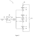
- FIG 2 illustrates an example of a high voltage dc power source 1 according to the present invention.
- the high voltage dc power source 1 in the following denoted dc power source 1 comprises one or more strings 4a-c connected in parallel, each string being subdivided into a plurality of dc power source units 8-11 connected in series. In figure 2 only one string is shown. The number of dc power source units 8-11 in series connection depends on the desired voltage level of the dc power source 1.
- Each string 4a-c is provided with at least one solid-state switch 12-15 configured to connect and disconnect the string. In figure 2 four switches 12-15 and four dc power source units 8-11 are shown.
- the dc power source 1 further comprises a control unit to turn on and off the switches.
- the control unit comprises one or more string control units 20, one for each string 4a-c in the dc power source 1. Since only one string is shown in figure 2 only one string control unit is shown.
- the string control unit controls the turn on and the turn off of the switches in its corresponding string.
- the string control unit 20 is configured, upon receiving a connecting order 23 from a main controller (not shown in figure 2 ) to connect the string 4a-c and thereby initiating a charging current.
- the string control unit 20 includes among other things suitable processing means, such as a Central Processing Unit.
- the string control unit 20 further includes a soft start module 21 configured to simultaneously control the switches 12-15 of the string to be alternately turned on and off so that a soft charging of an electronic device 19 connected in parallel with the string is achieved.
- the string control unit 20 is configured to execute the soft start module 21 upon receiving the connecting order 23.
- the electronic device 19 comprises for example a dc link capacitor in a power apparatus or another string in the dc power source 1. In the latter case the high voltage dc power source 1 can be used for equalising a voltage difference between parallel strings.
- the string control unit comprises a memory storage 22 for storing predefined switching patterns.
- the soft start module 21 When the string control unit 20 receives an order to connect the string, the soft start module 21 will retrieve a predefined switching pattern from the memory storage 22, and simultaneously control the switches of the string to be alternately turned on and off in accordance with the predefined switching pattern.
- the soft start module 21 is configured to generate a control signal 24 based on the switching pattern and the string control unit is configured to send the control signal 24 to each switch in the string.
- the switching patterns define the time intervals between turning the switches on and off and between turning the switches off an on and is determined during the design phase of the dc power source based on circuit parameters such as loop inductance, voltage level of the dc power source etc.
- the switching pattern is not based on a predefined switching pattern but on measurements of the charging current.
- the string control unit will receive measurement values of the charging current in the string from a current measuring device not shown in figure 2 .
- the switches are turned off in order for the current to decrease below the second threshold value before the switches are turned on again. This procedure will be repeated until the predetermined voltage value across the electronic device is achieved. At that time the charging current will not be able to reach above the first threshold value and the string will remain connected.
- Figure 3a-c shows three schematical examples of switching patterns, turning the switches in the string alternately on and off.
- the switching patterns could be predefined but could also be a result of measured values of the charging current as described above.
- On the x-axis of the diagram in figure 3a-c is shown the time instants at which the switches in the string are being simultaneously turned on and off during the soft charging of the electronic device.
- a dotted line 30 shows the time instant where the switches are being turned on for the first time after the connection order has been sent to the string control unit.
- On the y-axis of the diagram is shown the current switch status of the switches in the string being either ON or OFF. When the predetermined voltage value across the electronic device has been achieved, the switches will remain in the ON status during the operation of the dc power source.
- a switching pattern is shown where the time intervals between the turn on and the turn off (switch status ON) and the time interval between the turn off and the turn on (switch status OFF) of the switch remains constant through the
- figure 3d is shown the voltage value across the electronic device 19 using the switching pattern shown in figure 3c as the voltage increases until the predetermined voltage value has been achieved.
Landscapes
- Engineering & Computer Science (AREA)
- Power Engineering (AREA)
- Charge And Discharge Circuits For Batteries Or The Like (AREA)
- Dc-Dc Converters (AREA)
Claims (11)
- Hochspannungs-Gleichspannungsversorgung (1) zur Bereitstellung eines Ladestroms für eine elektronische Vorrichtung (19), umfassend:- einen oder mehrere parallel geschaltete Stränge (4a-4c), wobei jeder Strang in mehrere in Reihe geschaltete Gleichspannungsversorgungseinheiten (8-11) unterteilt ist und jeder Strang mit mehreren Festkörperschaltern (12-15) versehen ist, die dafür ausgelegt sind, den betreffenden Strang anzuschalten bzw. zu trennen,- eine Steuereinheit (20), die dafür ausgelegt ist, die mehreren Festkörperschalter (12-15) ein- bzw. auszuschalten, wobei jeder Festkörperschalter dafür ausgelegt ist, eine der Gleichspannungsversorgungseinheiten des Strangs anzuschalten bzw. zu trennen,dadurch gekennzeichnet, dass die Steuereinheit (20) dafür ausgelegt ist, nach Empfang eines Befehls zum Anschalten des Strangs die Festkörperschalter (12-15) des Strangs simultan derart zu steuern, dass sie abwechselnd ein- und ausgeschaltet werden, so dass ein sanftes Laden der elektronischen Vorrichtung (19) erzielt wird.
- Hochspannungs-Gleichspannungsversorgung gemäß Anspruch 1, wobei die Steuereinheit (20) dafür ausgelegt ist, das Zeitintervall zwischen dem Einschalten und dem Ausschalten oder das Zeitintervall zwischen dem Ausschalten und dem Einschalten der Festkörperschalter zu variieren, um den Ladestrom zu begrenzen, bis ein vorbestimmter Spannungswert über die elektronische Vorrichtung erreicht ist.
- Hochspannungs-Gleichspannungsversorgung gemäß Anspruch 2, wobei die Steuereinheit dafür ausgelegt ist, das Zeitintervall zwischen dem Einschalten und dem Ausschalten der Festkörperschalter schrittweise zu verlängern.
- Hochspannungs-Gleichspannungsversorgung gemäß Anspruch 2, wobei die Steuereinheit dafür ausgelegt ist, das Zeitintervall zwischen dem Ausschalten und dem Einschalten der Festkörperschalter schrittweise zu verkürzen.
- Hochspannungs-Gleichspannungsversorgung gemäß Anspruch 2, wobei die Steuereinheit (20) dafür ausgelegt ist, das Zeitintervall basierend auf gemessenen Werten des Ladestroms zu bestimmen.
- Hochspannungs-Gleichspannungsversorgung gemäß einem der Ansprüche 1 bis 4, wobei die Steuereinheit (20) dafür ausgelegt ist, die Festkörperschalter gemäß einem vorbestimmten Schaltschema zu steuern.
- Hochspannungs-Gleichspannungsversorgung gemäß einem der Ansprüche 1 bis 6, wobei die Gleichspannungsversorgung zwei oder mehr parallele Stränge aufweist und die Steuereinheit dafür ausgelegt ist, die mehreren Festkörperschalter des Strangs mit der höchsten Spannung derart zu steuern, dass sie abwechselnd ein- und ausgeschaltet werden, so dass ein sanftes Laden eines der anderen Stränge mit niedrigerer Spannung erzielt wird.
- Leistungsvorrichtung für ein Hochspannungs-Stromsystem, wobei die Leistungsvorrichtung einen spannungsgeführten Stromrichter mit einem parallel geschalteten Zwischenkreiskondensator sowie eine Hochspannungs-Gleichspannungsversorgung gemäß einem der Ansprüche 1 bis 7 aufweist.
- Verwendung der Hochspannungs-Gleichspannungsversorgung gemäß einem der Ansprüche 1 bis 7 zum Laden eines Zwischenkreiskondensators in einer Leistungsvorrichtung.
- Verwendung der Hochspannungs-Gleichspannungsversorgung gemäß einem der Ansprüche 1 bis 7 zum Laden eines STATCOM mit Batterieenergiespeicher.
- Verwendung der Hochspannungs-Gleichspannungsversorgung gemäß Anspruch 7 zum Gleichrichten der Spannung der parallel geschalteten Stränge.
Applications Claiming Priority (1)
| Application Number | Priority Date | Filing Date | Title |
|---|---|---|---|
| PCT/EP2011/050560 WO2012097866A1 (en) | 2011-01-18 | 2011-01-18 | A high voltage dc power source and a power apparatus for a high voltage electrical power system |
Publications (2)
| Publication Number | Publication Date |
|---|---|
| EP2666221A1 EP2666221A1 (de) | 2013-11-27 |
| EP2666221B1 true EP2666221B1 (de) | 2016-08-31 |
Family
ID=43903797
Family Applications (1)
| Application Number | Title | Priority Date | Filing Date |
|---|---|---|---|
| EP11701056.1A Not-in-force EP2666221B1 (de) | 2011-01-18 | 2011-01-18 | Eine hoch gleichspannungsversorgung und eine vorrichtung fur ein hoch spannung elektrischen versorgungssystem |
Country Status (5)
| Country | Link |
|---|---|
| US (1) | US8890491B2 (de) |
| EP (1) | EP2666221B1 (de) |
| CN (1) | CN103329386B (de) |
| CA (1) | CA2824895C (de) |
| WO (1) | WO2012097866A1 (de) |
Families Citing this family (3)
| Publication number | Priority date | Publication date | Assignee | Title |
|---|---|---|---|---|
| DE102010041016A1 (de) * | 2010-09-20 | 2012-03-22 | Sb Limotive Company Ltd. | Verfahren zum Einstellen einer Gleichspannungszwischenkreisspannung |
| EP3588777B1 (de) * | 2018-06-29 | 2021-09-29 | ZKW Group GmbH | Schaltungsanordnung zur steuerung eines elektronischen eingangsschalters |
| US12136837B1 (en) * | 2020-12-08 | 2024-11-05 | Bobbie Wilson | Charge balancing of parallel strings with zener diode and light emitting diode between cell terminal of the battery strings |
Family Cites Families (10)
| Publication number | Priority date | Publication date | Assignee | Title |
|---|---|---|---|---|
| US20030007369A1 (en) * | 1998-04-02 | 2003-01-09 | Gilbreth Mark G. | Power controller |
| WO2000059091A1 (fr) * | 1999-03-29 | 2000-10-05 | Seiko Epson Corporation | Equipement electronique et son procede de commande |
| WO2002080332A1 (en) * | 2001-03-30 | 2002-10-10 | Designline Limited | Battery management unit, system and method |
| DE10216831A1 (de) * | 2002-04-16 | 2003-10-30 | Sanyo Energy Europ Corporate G | Ladekontrollschaltung für ein Batteriepack aus wiederaufladbaren Batterieelementen |
| JP4025678B2 (ja) * | 2003-04-22 | 2007-12-26 | 富士重工業株式会社 | 充電装置及び充電方法 |
| US6838923B2 (en) * | 2003-05-16 | 2005-01-04 | Ballard Power Systems Inc. | Power supply and ultracapacitor based battery simulator |
| EP2036180B1 (de) | 2006-06-30 | 2016-11-16 | Abb Research Ltd. | Leistungskompensierer und verfahren zum bereitstellen eines schwarzstarts mit diesem kompensierer |
| JP4713513B2 (ja) * | 2007-02-13 | 2011-06-29 | プライムアースEvエナジー株式会社 | 充放電装置 |
| US20090243540A1 (en) * | 2008-04-01 | 2009-10-01 | Analog Express Inc. | Methods and apparatus for battery charging management |
| WO2009152849A1 (en) * | 2008-06-17 | 2009-12-23 | Abb Research Ltd | A power apparatus for a high voltage electrical power system |
-
2011
- 2011-01-18 CA CA2824895A patent/CA2824895C/en not_active Expired - Fee Related
- 2011-01-18 WO PCT/EP2011/050560 patent/WO2012097866A1/en not_active Ceased
- 2011-01-18 EP EP11701056.1A patent/EP2666221B1/de not_active Not-in-force
- 2011-01-18 CN CN201180065298.9A patent/CN103329386B/zh not_active Expired - Fee Related
-
2013
- 2013-07-18 US US13/945,709 patent/US8890491B2/en not_active Expired - Fee Related
Also Published As
| Publication number | Publication date |
|---|---|
| US8890491B2 (en) | 2014-11-18 |
| CN103329386B (zh) | 2016-08-17 |
| CA2824895C (en) | 2016-03-01 |
| WO2012097866A1 (en) | 2012-07-26 |
| US20130300379A1 (en) | 2013-11-14 |
| EP2666221A1 (de) | 2013-11-27 |
| CA2824895A1 (en) | 2012-07-26 |
| CN103329386A (zh) | 2013-09-25 |
Similar Documents
| Publication | Publication Date | Title |
|---|---|---|
| EP2916417B1 (de) | Energiespeicherungssystem und Steuerungsverfahren dafür | |
| US8575780B2 (en) | Power storage apparatus, method of operating the same, and power storage system | |
| CN110799925B (zh) | 聚集和供应能量的设备和方法 | |
| KR101084215B1 (ko) | 에너지 저장 시스템 및 이의 제어 방법 | |
| KR101412742B1 (ko) | 독립형 마이크로그리드 제어 시스템 및 그 제어방법 | |
| KR102234290B1 (ko) | 에너지 저장 시스템 및 그의 구동방법 | |
| US9509231B2 (en) | Power converter system, damping system, and method of operating a power converter system | |
| US20170214250A1 (en) | Energization control for establishing microgrids | |
| US9893550B2 (en) | Energy storage system and starting method thereof | |
| KR20150004376A (ko) | 배터리 용량의 관리 | |
| CN102667144A (zh) | 用于风力发电站的输出控制方法和输出控制单元 | |
| EP3010110B1 (de) | Netzgebundenes photovoltaisches stromerzeugungssystem | |
| US8890491B2 (en) | High voltage DC power source and a power apparatus for a high voltage electrical power system | |
| WO2020131005A1 (en) | Fault current control sub-system and related method | |
| KR101476337B1 (ko) | 에너지 저장 시스템 및 그 제어 방법 | |
| KR101698267B1 (ko) | 에너지 저장 시스템의 제어 방법 | |
| Ediriweera et al. | Hybrid energy storages for islanded microgrids with high solar pv penetration | |
| KR102303326B1 (ko) | 에너지 저장 시스템 | |
| Binduhewa et al. | Design and implementation of a novel controller for autonomous 2.5 kW wind power plant |
Legal Events
| Date | Code | Title | Description |
|---|---|---|---|
| PUAI | Public reference made under article 153(3) epc to a published international application that has entered the european phase |
Free format text: ORIGINAL CODE: 0009012 |
|
| 17P | Request for examination filed |
Effective date: 20130819 |
|
| AK | Designated contracting states |
Kind code of ref document: A1 Designated state(s): AL AT BE BG CH CY CZ DE DK EE ES FI FR GB GR HR HU IE IS IT LI LT LU LV MC MK MT NL NO PL PT RO RS SE SI SK SM TR |
|
| DAX | Request for extension of the european patent (deleted) | ||
| GRAP | Despatch of communication of intention to grant a patent |
Free format text: ORIGINAL CODE: EPIDOSNIGR1 |
|
| INTG | Intention to grant announced |
Effective date: 20160520 |
|
| GRAS | Grant fee paid |
Free format text: ORIGINAL CODE: EPIDOSNIGR3 |
|
| GRAA | (expected) grant |
Free format text: ORIGINAL CODE: 0009210 |
|
| AK | Designated contracting states |
Kind code of ref document: B1 Designated state(s): AL AT BE BG CH CY CZ DE DK EE ES FI FR GB GR HR HU IE IS IT LI LT LU LV MC MK MT NL NO PL PT RO RS SE SI SK SM TR |
|
| RAP1 | Party data changed (applicant data changed or rights of an application transferred) |
Owner name: ABB SCHWEIZ AG |
|
| REG | Reference to a national code |
Ref country code: CH Ref legal event code: EP Ref country code: GB Ref legal event code: FG4D |
|
| REG | Reference to a national code |
Ref country code: IE Ref legal event code: FG4D |
|
| REG | Reference to a national code |
Ref country code: DE Ref legal event code: R096 Ref document number: 602011029795 Country of ref document: DE |
|
| REG | Reference to a national code |
Ref country code: AT Ref legal event code: REF Ref document number: 825724 Country of ref document: AT Kind code of ref document: T Effective date: 20161015 |
|
| REG | Reference to a national code |
Ref country code: LT Ref legal event code: MG4D |
|
| REG | Reference to a national code |
Ref country code: NL Ref legal event code: MP Effective date: 20160831 |
|
| REG | Reference to a national code |
Ref country code: AT Ref legal event code: MK05 Ref document number: 825724 Country of ref document: AT Kind code of ref document: T Effective date: 20160831 |
|
| REG | Reference to a national code |
Ref country code: FR Ref legal event code: PLFP Year of fee payment: 7 |
|
| PG25 | Lapsed in a contracting state [announced via postgrant information from national office to epo] |
Ref country code: HR Free format text: LAPSE BECAUSE OF FAILURE TO SUBMIT A TRANSLATION OF THE DESCRIPTION OR TO PAY THE FEE WITHIN THE PRESCRIBED TIME-LIMIT Effective date: 20160831 Ref country code: NO Free format text: LAPSE BECAUSE OF FAILURE TO SUBMIT A TRANSLATION OF THE DESCRIPTION OR TO PAY THE FEE WITHIN THE PRESCRIBED TIME-LIMIT Effective date: 20161130 Ref country code: RS Free format text: LAPSE BECAUSE OF FAILURE TO SUBMIT A TRANSLATION OF THE DESCRIPTION OR TO PAY THE FEE WITHIN THE PRESCRIBED TIME-LIMIT Effective date: 20160831 Ref country code: FI Free format text: LAPSE BECAUSE OF FAILURE TO SUBMIT A TRANSLATION OF THE DESCRIPTION OR TO PAY THE FEE WITHIN THE PRESCRIBED TIME-LIMIT Effective date: 20160831 Ref country code: LT Free format text: LAPSE BECAUSE OF FAILURE TO SUBMIT A TRANSLATION OF THE DESCRIPTION OR TO PAY THE FEE WITHIN THE PRESCRIBED TIME-LIMIT Effective date: 20160831 |
|
| PG25 | Lapsed in a contracting state [announced via postgrant information from national office to epo] |
Ref country code: AT Free format text: LAPSE BECAUSE OF FAILURE TO SUBMIT A TRANSLATION OF THE DESCRIPTION OR TO PAY THE FEE WITHIN THE PRESCRIBED TIME-LIMIT Effective date: 20160831 Ref country code: GR Free format text: LAPSE BECAUSE OF FAILURE TO SUBMIT A TRANSLATION OF THE DESCRIPTION OR TO PAY THE FEE WITHIN THE PRESCRIBED TIME-LIMIT Effective date: 20161201 Ref country code: ES Free format text: LAPSE BECAUSE OF FAILURE TO SUBMIT A TRANSLATION OF THE DESCRIPTION OR TO PAY THE FEE WITHIN THE PRESCRIBED TIME-LIMIT Effective date: 20160831 Ref country code: LV Free format text: LAPSE BECAUSE OF FAILURE TO SUBMIT A TRANSLATION OF THE DESCRIPTION OR TO PAY THE FEE WITHIN THE PRESCRIBED TIME-LIMIT Effective date: 20160831 Ref country code: NL Free format text: LAPSE BECAUSE OF FAILURE TO SUBMIT A TRANSLATION OF THE DESCRIPTION OR TO PAY THE FEE WITHIN THE PRESCRIBED TIME-LIMIT Effective date: 20160831 Ref country code: SE Free format text: LAPSE BECAUSE OF FAILURE TO SUBMIT A TRANSLATION OF THE DESCRIPTION OR TO PAY THE FEE WITHIN THE PRESCRIBED TIME-LIMIT Effective date: 20160831 |
|
| PG25 | Lapsed in a contracting state [announced via postgrant information from national office to epo] |
Ref country code: RO Free format text: LAPSE BECAUSE OF FAILURE TO SUBMIT A TRANSLATION OF THE DESCRIPTION OR TO PAY THE FEE WITHIN THE PRESCRIBED TIME-LIMIT Effective date: 20160831 Ref country code: EE Free format text: LAPSE BECAUSE OF FAILURE TO SUBMIT A TRANSLATION OF THE DESCRIPTION OR TO PAY THE FEE WITHIN THE PRESCRIBED TIME-LIMIT Effective date: 20160831 |
|
| PG25 | Lapsed in a contracting state [announced via postgrant information from national office to epo] |
Ref country code: SM Free format text: LAPSE BECAUSE OF FAILURE TO SUBMIT A TRANSLATION OF THE DESCRIPTION OR TO PAY THE FEE WITHIN THE PRESCRIBED TIME-LIMIT Effective date: 20160831 Ref country code: SK Free format text: LAPSE BECAUSE OF FAILURE TO SUBMIT A TRANSLATION OF THE DESCRIPTION OR TO PAY THE FEE WITHIN THE PRESCRIBED TIME-LIMIT Effective date: 20160831 Ref country code: BE Free format text: LAPSE BECAUSE OF FAILURE TO SUBMIT A TRANSLATION OF THE DESCRIPTION OR TO PAY THE FEE WITHIN THE PRESCRIBED TIME-LIMIT Effective date: 20160831 Ref country code: DK Free format text: LAPSE BECAUSE OF FAILURE TO SUBMIT A TRANSLATION OF THE DESCRIPTION OR TO PAY THE FEE WITHIN THE PRESCRIBED TIME-LIMIT Effective date: 20160831 Ref country code: CZ Free format text: LAPSE BECAUSE OF FAILURE TO SUBMIT A TRANSLATION OF THE DESCRIPTION OR TO PAY THE FEE WITHIN THE PRESCRIBED TIME-LIMIT Effective date: 20160831 Ref country code: PT Free format text: LAPSE BECAUSE OF FAILURE TO SUBMIT A TRANSLATION OF THE DESCRIPTION OR TO PAY THE FEE WITHIN THE PRESCRIBED TIME-LIMIT Effective date: 20170102 Ref country code: PL Free format text: LAPSE BECAUSE OF FAILURE TO SUBMIT A TRANSLATION OF THE DESCRIPTION OR TO PAY THE FEE WITHIN THE PRESCRIBED TIME-LIMIT Effective date: 20160831 Ref country code: BG Free format text: LAPSE BECAUSE OF FAILURE TO SUBMIT A TRANSLATION OF THE DESCRIPTION OR TO PAY THE FEE WITHIN THE PRESCRIBED TIME-LIMIT Effective date: 20161130 |
|
| REG | Reference to a national code |
Ref country code: DE Ref legal event code: R097 Ref document number: 602011029795 Country of ref document: DE |
|
| PG25 | Lapsed in a contracting state [announced via postgrant information from national office to epo] |
Ref country code: IT Free format text: LAPSE BECAUSE OF FAILURE TO SUBMIT A TRANSLATION OF THE DESCRIPTION OR TO PAY THE FEE WITHIN THE PRESCRIBED TIME-LIMIT Effective date: 20160831 |
|
| PLBE | No opposition filed within time limit |
Free format text: ORIGINAL CODE: 0009261 |
|
| STAA | Information on the status of an ep patent application or granted ep patent |
Free format text: STATUS: NO OPPOSITION FILED WITHIN TIME LIMIT |
|
| 26N | No opposition filed |
Effective date: 20170601 |
|
| PG25 | Lapsed in a contracting state [announced via postgrant information from national office to epo] |
Ref country code: SI Free format text: LAPSE BECAUSE OF FAILURE TO SUBMIT A TRANSLATION OF THE DESCRIPTION OR TO PAY THE FEE WITHIN THE PRESCRIBED TIME-LIMIT Effective date: 20160831 |
|
| PG25 | Lapsed in a contracting state [announced via postgrant information from national office to epo] |
Ref country code: MC Free format text: LAPSE BECAUSE OF FAILURE TO SUBMIT A TRANSLATION OF THE DESCRIPTION OR TO PAY THE FEE WITHIN THE PRESCRIBED TIME-LIMIT Effective date: 20160831 |
|
| REG | Reference to a national code |
Ref country code: IE Ref legal event code: MM4A |
|
| PG25 | Lapsed in a contracting state [announced via postgrant information from national office to epo] |
Ref country code: LU Free format text: LAPSE BECAUSE OF NON-PAYMENT OF DUE FEES Effective date: 20170118 |
|
| REG | Reference to a national code |
Ref country code: FR Ref legal event code: PLFP Year of fee payment: 8 |
|
| PG25 | Lapsed in a contracting state [announced via postgrant information from national office to epo] |
Ref country code: IE Free format text: LAPSE BECAUSE OF NON-PAYMENT OF DUE FEES Effective date: 20170118 |
|
| PGFP | Annual fee paid to national office [announced via postgrant information from national office to epo] |
Ref country code: DE Payment date: 20180122 Year of fee payment: 8 Ref country code: CH Payment date: 20180119 Year of fee payment: 8 Ref country code: GB Payment date: 20180119 Year of fee payment: 8 |
|
| PGFP | Annual fee paid to national office [announced via postgrant information from national office to epo] |
Ref country code: FR Payment date: 20180119 Year of fee payment: 8 |
|
| REG | Reference to a national code |
Ref country code: DE Ref legal event code: R084 Ref document number: 602011029795 Country of ref document: DE |
|
| PG25 | Lapsed in a contracting state [announced via postgrant information from national office to epo] |
Ref country code: MT Free format text: LAPSE BECAUSE OF NON-PAYMENT OF DUE FEES Effective date: 20170118 |
|
| PG25 | Lapsed in a contracting state [announced via postgrant information from national office to epo] |
Ref country code: AL Free format text: LAPSE BECAUSE OF FAILURE TO SUBMIT A TRANSLATION OF THE DESCRIPTION OR TO PAY THE FEE WITHIN THE PRESCRIBED TIME-LIMIT Effective date: 20160831 |
|
| PG25 | Lapsed in a contracting state [announced via postgrant information from national office to epo] |
Ref country code: HU Free format text: LAPSE BECAUSE OF FAILURE TO SUBMIT A TRANSLATION OF THE DESCRIPTION OR TO PAY THE FEE WITHIN THE PRESCRIBED TIME-LIMIT; INVALID AB INITIO Effective date: 20110118 |
|
| REG | Reference to a national code |
Ref country code: DE Ref legal event code: R119 Ref document number: 602011029795 Country of ref document: DE |
|
| REG | Reference to a national code |
Ref country code: CH Ref legal event code: PL |
|
| GBPC | Gb: european patent ceased through non-payment of renewal fee |
Effective date: 20190118 |
|
| PG25 | Lapsed in a contracting state [announced via postgrant information from national office to epo] |
Ref country code: CY Free format text: LAPSE BECAUSE OF NON-PAYMENT OF DUE FEES Effective date: 20160831 Ref country code: DE Free format text: LAPSE BECAUSE OF NON-PAYMENT OF DUE FEES Effective date: 20190801 Ref country code: FR Free format text: LAPSE BECAUSE OF NON-PAYMENT OF DUE FEES Effective date: 20190131 |
|
| PG25 | Lapsed in a contracting state [announced via postgrant information from national office to epo] |
Ref country code: MK Free format text: LAPSE BECAUSE OF FAILURE TO SUBMIT A TRANSLATION OF THE DESCRIPTION OR TO PAY THE FEE WITHIN THE PRESCRIBED TIME-LIMIT Effective date: 20160831 |
|
| PG25 | Lapsed in a contracting state [announced via postgrant information from national office to epo] |
Ref country code: CH Free format text: LAPSE BECAUSE OF NON-PAYMENT OF DUE FEES Effective date: 20190131 Ref country code: LI Free format text: LAPSE BECAUSE OF NON-PAYMENT OF DUE FEES Effective date: 20190131 Ref country code: GB Free format text: LAPSE BECAUSE OF NON-PAYMENT OF DUE FEES Effective date: 20190118 |
|
| PG25 | Lapsed in a contracting state [announced via postgrant information from national office to epo] |
Ref country code: TR Free format text: LAPSE BECAUSE OF FAILURE TO SUBMIT A TRANSLATION OF THE DESCRIPTION OR TO PAY THE FEE WITHIN THE PRESCRIBED TIME-LIMIT Effective date: 20160831 |
|
| PG25 | Lapsed in a contracting state [announced via postgrant information from national office to epo] |
Ref country code: IS Free format text: LAPSE BECAUSE OF FAILURE TO SUBMIT A TRANSLATION OF THE DESCRIPTION OR TO PAY THE FEE WITHIN THE PRESCRIBED TIME-LIMIT Effective date: 20161231 |