EP2666413A1 - Mesure de la densité osseuse - Google Patents
Mesure de la densité osseuse Download PDFInfo
- Publication number
- EP2666413A1 EP2666413A1 EP12169102.6A EP12169102A EP2666413A1 EP 2666413 A1 EP2666413 A1 EP 2666413A1 EP 12169102 A EP12169102 A EP 12169102A EP 2666413 A1 EP2666413 A1 EP 2666413A1
- Authority
- EP
- European Patent Office
- Prior art keywords
- tissue
- ray
- interest
- region
- distribution
- Prior art date
- Legal status (The legal status is an assumption and is not a legal conclusion. Google has not performed a legal analysis and makes no representation as to the accuracy of the status listed.)
- Withdrawn
Links
Images



Classifications
-
- A—HUMAN NECESSITIES
- A61—MEDICAL OR VETERINARY SCIENCE; HYGIENE
- A61B—DIAGNOSIS; SURGERY; IDENTIFICATION
- A61B6/00—Apparatus or devices for radiation diagnosis; Apparatus or devices for radiation diagnosis combined with radiation therapy equipment
- A61B6/52—Devices using data or image processing specially adapted for radiation diagnosis
- A61B6/5211—Devices using data or image processing specially adapted for radiation diagnosis involving processing of medical diagnostic data
- A61B6/5217—Devices using data or image processing specially adapted for radiation diagnosis involving processing of medical diagnostic data extracting a diagnostic or physiological parameter from medical diagnostic data
-
- A—HUMAN NECESSITIES
- A61—MEDICAL OR VETERINARY SCIENCE; HYGIENE
- A61B—DIAGNOSIS; SURGERY; IDENTIFICATION
- A61B6/00—Apparatus or devices for radiation diagnosis; Apparatus or devices for radiation diagnosis combined with radiation therapy equipment
- A61B6/50—Apparatus or devices for radiation diagnosis; Apparatus or devices for radiation diagnosis combined with radiation therapy equipment specially adapted for specific body parts; specially adapted for specific clinical applications
- A61B6/505—Apparatus or devices for radiation diagnosis; Apparatus or devices for radiation diagnosis combined with radiation therapy equipment specially adapted for specific body parts; specially adapted for specific clinical applications for diagnosis of bone
-
- A—HUMAN NECESSITIES
- A61—MEDICAL OR VETERINARY SCIENCE; HYGIENE
- A61B—DIAGNOSIS; SURGERY; IDENTIFICATION
- A61B6/00—Apparatus or devices for radiation diagnosis; Apparatus or devices for radiation diagnosis combined with radiation therapy equipment
- A61B6/58—Testing, adjusting or calibrating thereof
- A61B6/582—Calibration
- A61B6/583—Calibration using calibration phantoms
-
- G—PHYSICS
- G06—COMPUTING OR CALCULATING; COUNTING
- G06T—IMAGE DATA PROCESSING OR GENERATION, IN GENERAL
- G06T7/00—Image analysis
- G06T7/0002—Inspection of images, e.g. flaw detection
- G06T7/0012—Biomedical image inspection
-
- G—PHYSICS
- G16—INFORMATION AND COMMUNICATION TECHNOLOGY [ICT] SPECIALLY ADAPTED FOR SPECIFIC APPLICATION FIELDS
- G16H—HEALTHCARE INFORMATICS, i.e. INFORMATION AND COMMUNICATION TECHNOLOGY [ICT] SPECIALLY ADAPTED FOR THE HANDLING OR PROCESSING OF MEDICAL OR HEALTHCARE DATA
- G16H50/00—ICT specially adapted for medical diagnosis, medical simulation or medical data mining; ICT specially adapted for detecting, monitoring or modelling epidemics or pandemics
- G16H50/30—ICT specially adapted for medical diagnosis, medical simulation or medical data mining; ICT specially adapted for detecting, monitoring or modelling epidemics or pandemics for calculating health indices; for individual health risk assessment
Definitions
- the invention relates to the field of computer assisted surgery (CAS). Particularly, the invention relates to a computer software based method for identifying a density distribution of a tissue like, for example, bone. Furthermore, the invention relates to a corresponding device.
- CAS computer assisted surgery
- images are generated by means of a system including an X-ray source and an X-ray detector, wherein radiation is emitted from the X-ray source and is detected by the X-ray detector after passing through an object.
- the X-ray detector may be an array of sensing elements for converting the radiation into a signal which can be processed by an appropriate processing unit. Based on these signals from the sensing elements, wherein each of these sensing elements may be related to a pixel, the processing unit generates an X-ray image which can be shown on a monitor or which can be printed. Accordingly, such an image is a two dimensional projection image and has the drawback that it does not include any depth information.
- a plurality of images can be generated from different viewing angles.
- An appropriate processing unit may generate a 3D visualization on the basis of such images.
- this has the drawback that a patient must be exposed to a high amount of radiation to achieve a 3D visualization.
- a method for determining a tissue density comprising, in general, the steps of receiving an X-ray image of a region of interest and information about a theoretical distribution of more or less dens tissue in the region of interest, comparing a pixel of the X-ray image related to tissue with a pixel related to a reference body, estimating an actual distibution of tissue density based on the received information and the result of the pixel comparison.
- the X-ray projection image may be generated from a first imaging direction, wherein this image including a region of interest of a subject and the reference body.
- the reference body may include a predetermined density and thus a predetermined X-ray attenuation.
- the X-ray projection image may comprise a plurality of pixels, wherein each of the pixels is associated with one X-ray beam path and represents an attenuation of the X-ray beam along its path through the subject. Usually, a distinct grey level of one pixel in X-ray image corresponds to a distinct level of attenuation of the X-ray beam.
- the received information may include a theoretical distribution of harder, i.e. more dens tissue and softer, i.e. less dens tissue which can be expected along the path of the X-ray beam.
- the signal of one sensing element of the X-ray detector corresponds to an X-ray attenuation of the X-ray beam through an object.
- one sensing element may correspond to one pixel of an X-ray image. Accordingly, the remaining X-ray radiation (emitted X-ray radiation minus attenuation of the same) as sensed by one sensing element can be assigned to a specific grey level for a pixel corresponding to the sensing element.
- the grey level of one of the pixels related to the region of interest is compared with the grey level of one of the pixels related to the reference body, so that an actual distribution of harder tissue and of softer tissue along the path of the X-ray beam related to the pixel related to the region of interest can be estimated, based on the compared grey levels representing X-ray beam attenuations, and the theoretical distribution of harder and softer tissue.
- a distruibution of the density of differing tissues is thus determined along the path of an X-ray beam associated with one pixel.
- the X-ray image comprises a plurality of pixels in the region of interest and the steps of comparing and of estimating are performed for each pixel of the region of interest.
- the method further comprises the step of receiving a second X-ray projection image generated from a second imaging direction which is different to the first imaging direction, wherein the second image may also include the region of interest.
- the estimation of the actual distribution of harder tissue and softer tissue may be performed for each voxel of the region of interest.
- voxel encompasses a point in a three dimensional space
- pixel denotes a point in a two dimensional space.
- a three dimensional density distribution may be estimated based on a plurality, i.e. at least two X-ray images generated from different imaging directions, and based on information concerning a theoretical distribution of harder and softer tissue. That is, not only the typical distribution but also actual values can be taken into account for the estimation of the density distribution in a three dimensional space. For example, a pathologically changed density of only a portion in the region of interest can be identified by an estimation based on at least two X-ray images from different directions.
- the method further comprises the step of identifying bone tissue in the region of interest, wherein an actual distribution of harder bone tissue and softer bone tissue is estimated.
- a density distribution may be estimated taking into account a typical distribution of more or less dens tissue in a region of interest like a bone, i.e. for example a tissue distribution present in a bone model.
- the term "bone model” encompasses, for example, a 3D model of a bone.
- the bone model may be generated based on at least one 3D scan of at least one real bone of the same kind, for example a femur or humerus, and/or by forming an average from a plurality of 3D scans.
- a database may contain several models of each bone (e.g. tibia, femur, humerus) including bone models of different ages, genders and individual sizes. Various aspects like for example a distribution of differing tissues may be taken from a 3D model. Furthermore, an attenuation value along a projection path may be calculated based on a bone model, providing a value of an attenuation which can be expected at a distinct position when a bone would be imaged from a specific direction.
- models of each bone e.g. tibia, femur, humerus
- Various aspects like for example a distribution of differing tissues may be taken from a 3D model.
- an attenuation value along a projection path may be calculated based on a bone model, providing a value of an attenuation which can be expected at a distinct position when a bone would be imaged from a specific direction.
- the method further comprises the step of visualizing the density distribution on a monitor.
- the different density values may be visualized by different colors, by different grey levels, by more or less narrow array of points or by more or less narrow lines of hatchings.
- portions having a density which differs from a theoretically expectable density may be high-lighted by for example flashing.
- the reference body includes a plurality of portions with different predetermined densities.
- a plurality of values i.e. steps of grey levels corresponding to density values can be compared with the values of the at least one pixel of the imaged region of interest.
- a device for determining a tissue density comprising a processing unit adapted to perform the steps of the above described method.
- the device comprises a storage device providing a database of for example bone models. It will be understood, that such storage means may also be provided in a network to which the device may be connected and information related to the bone model, i.e. different types of models and density values thereof, may be received over that network.
- the device further comprises an X-ray imaging unit for generating an X-ray image, wherein the X-ray imaging unit may be capable of generating X-ray images from different imaging directions.
- the device further comprises an input device for manually identifying a region of interest.
- Such input means may be for example a computer keyboard, a computer mouse or a touch screen, to control a pointing device like a cursor on a monitor screen which may also be included in the device.
- a computer program including sets of instructions which when executed on a processing unit of an above described device, cause the device to perform the steps of the above described method.
- a corresponding computer program may preferably be loaded into a work memory of a data processor.
- the data processor or processing unit may thus be equipped to carry out at least a part of the method.
- the invention relates to a computer-readable medium such as a CD-ROM at which the computer program may be stored.
- the computer program may also be presented over a network like the World Wide Web and can be downloaded into the working memory of the data processor from such a network.
- Fig. 1 illustrates the principle of the steps performed in accordance with one embodiment. It will be understood that the steps described, are major steps, wherein these major steps might be differentiated or divided into several sub-steps. Furthermore, there might be also sub-steps between these major steps.
- an image is received for example from an X-ray imaging unit in step S11, the image being generated from a first direction and shows a region of interest as well as a reference body.
- the region of interest for example a portion of a bone is identified in the received image.
- step S 13 information regarding the distribution of density in the identified bone portion is received.
- a bone model of a long bone may be received including an average distribution of more or less dens tissue, i.e. of harder bone tissue present in a corticalis of the bone and softer bone tissue present in a marrow channel of the bone. Knowing the tissue distribution leads to an attenuation value which can be expected.
- step S 14 the value of a pixel of the region of interest is compared with a value of a pixel of the reference body, wherein each of such pixel values represents an overall attenuation of the X-ray beam impinging a respective sensing element of an X-ray detector.
- step S 15 a distribution of density along the path of an X-ray beam is estimated based on the comparison of the pixel value (S 14) and the bone model (S 13).
- step S30 the X-ray image together with the density information is visualized in step S30.
- steps S 14 and S15 are performed again for each of that pixels.
- an estimation of a three dimensional distribution of the density can be achieved on the basis of the X-ray image generated in step S11.
- step S21 is performed next, i.e. a further image is received for example from the X-ray imaging unit, the image being generated from a second direction showing also the region of interest.
- step S22 the region of interest is identified in the received image.
- step S23 the value of a pixel of the region of interest is compared with a value of a pixel of the reference body.
- step S24 a three dimensional distribution of density is estimated based on the comparison of the pixel value of the second image (S23) and the distribution as estimated in step S 15 taking into account the bone model (S13).
- steps S23 and S24 are performed at least twice, for a plurality of pixels of the second X-ray image.
- step S30 one of the X-ray images together with the verified or revised, thus improved density information is visualized in step S30.
- Fig. 2 shows an exemplary embodiment of a device. Substantially necessary for performing the steps according to the method, the device comprises a processing unit 10 and a monitor 16.
- the exemplary imaging device 20 includes an X-ray source 24, and an X-ray detector 26, wherein these two devices are mounted on a C-arm 22. It will be understood that the device may also comprise another non-invasive imaging modality like a computer tomography device as imaging device instead of or additional to the shown C-arm based X-ray device, to generated individual projection images.
- the device in Fig. 2 includes an input device 14, by means of which for example a manual determination of a position on a bone surface may be performed. Also shown is a connection to a database 12, located for example in a network.
- a region of interest 50 for example a bone of a patient may be located, a density distribution of which may be of interest.
- Fig. 3A and Fig. 3B show exemplary embodiments of reference bodies.
- eight reference bodies are depicted each formed like a piece of cake. It will be understood that one reference body may have any other form, for example rectangular, circular, or cubical. Preferably, a reference body does not have any sharp edges or tips to avoid any injury of a person.
- each of the reference bodies may comprise a material with a distinct X-ray attenuation.
- reference body 300 may be made from a less dens material as each of the other reference bodies 400, 500, 600, 700, 800, 900 and 1000.
- reference body 300 is shown in Fig. 3A with the brightest grey level. Consequently, reference body 1000 may be made from a more dens material as each of the other reference bodies, thus being shown with the darkest grey level.
- the density of a material affects the X-ray attenuation, i.e. the possibility for an X-ray beam to pass the material, for example without being scattered.
- Fig. 3B shows an embodiment of a reference body 60 having a plurality of segments with different X-ray attenuation.
- This reference body comprises the form of a disk which may be made by a plurality of separate pieces each with a material having a different X-ray attenuation. It will be understood that also a reference body 60 with a plurality of different X-ray attenuations may be arbitrarily formed, for example like a cube or a cylinder.
- a possible positioning of a reference body 60 is shown.
- the reference body 60 may be laid under a body of a patient on a table of an X-ray system.
- the position should be in the vicinity of the region of interest, i.e. the portion of a body which is intended to be imaged by means of the X-ray system.
- the position should be within the field of view of the X-ray system to ensure that the reference body will be imaged together with the region of interest.
- Fig. 4 it may be intended to image the hip joint from an anterior to posterior direction, i.e. from above (when the patient lie on the back).
- An exemplary image of a hip joint also including a reference body is shown in Fig. 5B .
- the reference body does not have to be in contact with the patient during the imaging.
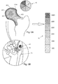
- Fig. 5B is a schematically illustration of an X-ray image including a femur 70, wherein the head 50 of the femur 70 may be considered as region of interest, as well as a reference body 60.
- the head 50 of the femur 70 is also shown in figure 5A which is an enlarged detail view of the region of interest and the reference body of figure 5B .
- the head of the femur includes hatchings, wherein these hatchings represent areas with different densities.
- the area 1000 forming substantially the corticalis of the bone includes a high density as indicated in the scale 80 at the right side of figure 5A .
- the density firstly decreases from the edge area 1000, i.e. the corticalis, in the direction to the area in the middle of the head. That is, adjacent the edge area 1000, an area 800 and then an area 600 having less density are present. However, in the middle of the head of the femur a further area 800 with an relatively increased density can be seen, whereas in the middle of the neck of the femur an area 400 with further decreased density is present.
- references signs 100, 200, 300, 400, 500, 600, 700, 800, 900, and 1000, as used in figures 3A and 5A both may denote an area and may indicate an order of magnitude of the density.
- a femur head 70 is shown but simplified in that it only includes a corticalis 72 and marrow 74.
- the corticalis includes a portion 76 which may be pathologically changed.
- a first group of which (X1, X2, X3, X4) passes through the head of the femur 70 from a first direction and a second group of which (Y1, Y2, Y3, Y4, Y5) passes through the head of the femur 70 from a second direction.
- the X-ray attenuation (A) of beam X1 is higher than that of for example beam X3, although beam X1 only passes through corticalis tissue and beam X3 passes through both corticalis and marrow.
- the attenuation (A) in the harder corticalis is higher than in the softer marrow, an X-ray beam has to pass through more marrow than corticalis to be subjected to a comparable attenuation.
- the first result can be improved, since a density value corresponding to beam Y4 deviates from an expectable attenuation (A) value and thus density value, as shown in Fig. 7 .
- A expectable attenuation
- the computer program may be stored/distributed on a suitable medium such as an optical storage medium or a solid-state medium supplied together with or as a part of another hardware, but may also be distributed in other forms, such as via the Internet or other wired or wireless telecommunication systems. Any reference signs in the claims should not be construed as limiting the scope.
Landscapes
- Health & Medical Sciences (AREA)
- Engineering & Computer Science (AREA)
- Life Sciences & Earth Sciences (AREA)
- Medical Informatics (AREA)
- General Health & Medical Sciences (AREA)
- Public Health (AREA)
- Physics & Mathematics (AREA)
- Radiology & Medical Imaging (AREA)
- Nuclear Medicine, Radiotherapy & Molecular Imaging (AREA)
- Pathology (AREA)
- Biomedical Technology (AREA)
- Molecular Biology (AREA)
- High Energy & Nuclear Physics (AREA)
- Biophysics (AREA)
- Heart & Thoracic Surgery (AREA)
- Surgery (AREA)
- Animal Behavior & Ethology (AREA)
- Veterinary Medicine (AREA)
- Optics & Photonics (AREA)
- Computer Vision & Pattern Recognition (AREA)
- Physiology (AREA)
- Oral & Maxillofacial Surgery (AREA)
- Dentistry (AREA)
- Orthopedic Medicine & Surgery (AREA)
- Quality & Reliability (AREA)
- Theoretical Computer Science (AREA)
- General Physics & Mathematics (AREA)
- Data Mining & Analysis (AREA)
- Databases & Information Systems (AREA)
- Epidemiology (AREA)
- Primary Health Care (AREA)
- Apparatus For Radiation Diagnosis (AREA)
Priority Applications (2)
| Application Number | Priority Date | Filing Date | Title |
|---|---|---|---|
| EP12169102.6A EP2666413A1 (fr) | 2012-05-23 | 2012-05-23 | Mesure de la densité osseuse |
| US13/900,937 US20130315371A1 (en) | 2012-05-23 | 2013-05-23 | Bone density measurement |
Applications Claiming Priority (1)
| Application Number | Priority Date | Filing Date | Title |
|---|---|---|---|
| EP12169102.6A EP2666413A1 (fr) | 2012-05-23 | 2012-05-23 | Mesure de la densité osseuse |
Publications (1)
| Publication Number | Publication Date |
|---|---|
| EP2666413A1 true EP2666413A1 (fr) | 2013-11-27 |
Family
ID=46147340
Family Applications (1)
| Application Number | Title | Priority Date | Filing Date |
|---|---|---|---|
| EP12169102.6A Withdrawn EP2666413A1 (fr) | 2012-05-23 | 2012-05-23 | Mesure de la densité osseuse |
Country Status (2)
| Country | Link |
|---|---|
| US (1) | US20130315371A1 (fr) |
| EP (1) | EP2666413A1 (fr) |
Families Citing this family (7)
| Publication number | Priority date | Publication date | Assignee | Title |
|---|---|---|---|---|
| JP6539748B2 (ja) * | 2015-10-27 | 2019-07-03 | 株式会社日立製作所 | X線ctデータ処理装置、及び、これを搭載したx線ct装置 |
| EP3541270A4 (fr) | 2016-11-18 | 2020-06-10 | Stryker Corp. | Procédé et appareil destinés au traitement d'une articulation, comprenant le traitement d'un conflit fémoro-acétabulaire de type came dans une articulation de la hanche et d'un conflit fémoro-acétabulaire de type pince dans une articulation de la hanche |
| US11464569B2 (en) | 2018-01-29 | 2022-10-11 | Stryker Corporation | Systems and methods for pre-operative visualization of a joint |
| US12502218B2 (en) | 2019-02-08 | 2025-12-23 | Stryker Corporation | Systems and methods for treating a joint |
| CN115942913B (zh) | 2020-02-21 | 2026-01-06 | 史赛克公司 | 用于在关节手术程序期间视觉引导骨去除的系统和方法 |
| WO2022133442A1 (fr) | 2020-12-15 | 2022-06-23 | Stryker Corporation | Systèmes et procédés pour générer un modèle tridimensionnel d'une articulation à partir d'images bidimensionnelles |
| WO2024257540A1 (fr) * | 2023-06-11 | 2024-12-19 | 国立大学法人東北大学 | Dispositif, procédé et programme d'aide à la conception de corps pouvant être fixé, et corps pouvant être fixé |
Citations (1)
| Publication number | Priority date | Publication date | Assignee | Title |
|---|---|---|---|---|
| DE29920673U1 (de) * | 1999-05-31 | 2000-08-17 | Herzog, Rainer, 90537 Feucht | Automatische Knochen-Dichte und -Struktur Bestimmung durch Ermittlung der Gradienten von Referenzkörpern und Texturbestimmung |
Family Cites Families (5)
| Publication number | Priority date | Publication date | Assignee | Title |
|---|---|---|---|---|
| EP1078252A4 (fr) * | 1998-03-02 | 2007-05-30 | Image Analysis Inc | Osteodensitometrie par rayons x informatisee |
| US6904123B2 (en) * | 2000-08-29 | 2005-06-07 | Imaging Therapeutics, Inc. | Methods and devices for quantitative analysis of x-ray images |
| US7558611B2 (en) * | 2001-11-24 | 2009-07-07 | Image Analysis, Inc. | Automatic detection and quantification of coronary and aortic calcium |
| US20050077459A1 (en) * | 2003-02-19 | 2005-04-14 | Engler Mark J. | Radiation phantom |
| DE10352013B4 (de) * | 2003-11-07 | 2008-02-07 | Siemens Ag | Verfahren und Vorrichtung zur ortsaufgelösten Bestimmung der Elementkonzentrationen in Untersuchungsobjekten |
-
2012
- 2012-05-23 EP EP12169102.6A patent/EP2666413A1/fr not_active Withdrawn
-
2013
- 2013-05-23 US US13/900,937 patent/US20130315371A1/en not_active Abandoned
Patent Citations (1)
| Publication number | Priority date | Publication date | Assignee | Title |
|---|---|---|---|---|
| DE29920673U1 (de) * | 1999-05-31 | 2000-08-17 | Herzog, Rainer, 90537 Feucht | Automatische Knochen-Dichte und -Struktur Bestimmung durch Ermittlung der Gradienten von Referenzkörpern und Texturbestimmung |
Non-Patent Citations (5)
| Title |
|---|
| A.P. SCHULZ ET AL., THE OPEN ORTHOPAEDICS JOURNAL, vol. 6, 2012, pages 1 - 7 |
| ANONYMOUS: "Mindways Software Inc., Transform your CT scanner into the ultimate bone analyzer", INTERNET ARTICLE, 13 October 2011 (2011-10-13), Retrieved from the Internet <URL:http://web.archive.org/web/20110513061248/http://www.qct.com/> [retrieved on 20120802] * |
| LUDOVIC HUMBERT ET AL: "3D reconstruction of both shape and Bone Mineral Density distribution of the femur from DXA images", BIOMEDICAL IMAGING: FROM NANO TO MACRO, 2010 IEEE INTERNATIONAL SYMPOSIUM ON, IEEE, PISCATAWAY, NJ, USA, 14 April 2010 (2010-04-14), pages 456 - 459, XP031693582, ISBN: 978-1-4244-4125-9 * |
| SAMI P VÃ Ã NÃ NEN ET AL: "Estimation of 3D shape, internal density and mechanics of proximal femur by combining bone mineral density images with shape and density templates", BIOMECHANICS AND MODELING IN MECHANOBIOLOGY, SPRINGER, BERLIN, DE, vol. 11, no. 6, 11 October 2011 (2011-10-11), pages 791 - 800, XP035065099, ISSN: 1617-7940, DOI: 10.1007/S10237-011-0352-9 * |
| TRISTAN WHITMARSH ET AL: "Reconstructing the 3D Shape and Bone Mineral Density Distribution of the Proximal Femur From Dual-Energy X-Ray Absorptiometry", IEEE TRANSACTIONS ON MEDICAL IMAGING, IEEE SERVICE CENTER, PISCATAWAY, NJ, US, vol. 30, no. 12, 1 December 2011 (2011-12-01), pages 2101 - 2114, XP011380086, ISSN: 0278-0062, DOI: 10.1109/TMI.2011.2163074 * |
Also Published As
| Publication number | Publication date |
|---|---|
| US20130315371A1 (en) | 2013-11-28 |
Similar Documents
| Publication | Publication Date | Title |
|---|---|---|
| EP2666413A1 (fr) | Mesure de la densité osseuse | |
| JP6736832B2 (ja) | 解剖学的関節の損傷を示す意思決定支援材料を作成するためのシステムおよび方法 | |
| US20170273614A1 (en) | Systems and methods for measuring and assessing spine instability | |
| JP5399225B2 (ja) | 画像処理装置および方法並びにプログラム | |
| US20210121147A1 (en) | Method For Visualizing A Bone | |
| CN104395930A (zh) | 用于定位脊柱的方法、设备和系统 | |
| JPWO2016129682A1 (ja) | 骨解析装置 | |
| JP6659501B2 (ja) | 軟骨定量化装置、方法およびプログラム | |
| JP2024504867A (ja) | 断層撮影スキャンの画像ベースの計画 | |
| Ibrahim et al. | Influence of object location in different FOVs on trabecular bone microstructure measurements of human mandible: a cone beam CT study | |
| JP2009511124A (ja) | 散乱補正 | |
| CN103442640B (zh) | 骨诊断图像显示装置 | |
| JP2017093879A (ja) | X線測定システム及びx線検出データ処理方法 | |
| JP5694309B2 (ja) | デジタル画像減算 | |
| JP7819287B2 (ja) | 拡張された2次元画像データを提供する装置及び方法 | |
| JP2020523049A (ja) | 解剖学的関節の損傷を示す意思決定支援資料の作成 | |
| Lagacé et al. | 3D reconstruction of the scapula from biplanar radiographs | |
| JP5894374B2 (ja) | 骨塩量測定装置 | |
| US12236531B2 (en) | Meniscus projection plane setting apparatus, meniscus projection plane setting method, and meniscus projection plane setting program | |
| JP7271362B2 (ja) | 医用画像処理装置、医用画像処理システム、医用画像処理プログラム、及び医用画像処理方法 | |
| WO2022085493A1 (fr) | Appareil de traitement d'image médicale | |
| Westermann et al. | Three-dimensional characterization of the anterior cruciate ligament's femoral footprint | |
| JP6695133B2 (ja) | X線測定装置 | |
| JP7547950B2 (ja) | 動態解析装置及びプログラム | |
| WO2013038284A1 (fr) | Génération d'un modèle tridimensionnel d'un objet d'intérêt |
Legal Events
| Date | Code | Title | Description |
|---|---|---|---|
| PUAI | Public reference made under article 153(3) epc to a published international application that has entered the european phase |
Free format text: ORIGINAL CODE: 0009012 |
|
| AK | Designated contracting states |
Kind code of ref document: A1 Designated state(s): AL AT BE BG CH CY CZ DE DK EE ES FI FR GB GR HR HU IE IS IT LI LT LU LV MC MK MT NL NO PL PT RO RS SE SI SK SM TR |
|
| AX | Request for extension of the european patent |
Extension state: BA ME |
|
| STAA | Information on the status of an ep patent application or granted ep patent |
Free format text: STATUS: THE APPLICATION IS DEEMED TO BE WITHDRAWN |
|
| 18D | Application deemed to be withdrawn |
Effective date: 20140528 |