EP2666532B2 - Unité de filtration pour un système de barrière - Google Patents
Unité de filtration pour un système de barrière Download PDFInfo
- Publication number
- EP2666532B2 EP2666532B2 EP13161197.2A EP13161197A EP2666532B2 EP 2666532 B2 EP2666532 B2 EP 2666532B2 EP 13161197 A EP13161197 A EP 13161197A EP 2666532 B2 EP2666532 B2 EP 2666532B2
- Authority
- EP
- European Patent Office
- Prior art keywords
- filter
- piston
- filter unit
- cover
- unit according
- Prior art date
- Legal status (The legal status is an assumption and is not a legal conclusion. Google has not performed a legal analysis and makes no representation as to the accuracy of the status listed.)
- Active
Links
Images


Classifications
-
- B—PERFORMING OPERATIONS; TRANSPORTING
- B01—PHYSICAL OR CHEMICAL PROCESSES OR APPARATUS IN GENERAL
- B01D—SEPARATION
- B01D46/00—Filters or filtering processes specially modified for separating dispersed particles from gases or vapours
- B01D46/0084—Filters or filtering processes specially modified for separating dispersed particles from gases or vapours provided with safety means
- B01D46/0091—Including arrangements for environmental or personal protection
-
- B—PERFORMING OPERATIONS; TRANSPORTING
- B01—PHYSICAL OR CHEMICAL PROCESSES OR APPARATUS IN GENERAL
- B01D—SEPARATION
- B01D29/00—Filters with filtering elements stationary during filtration, e.g. pressure or suction filters, not covered by groups B01D24/00 - B01D27/00; Filtering elements therefor
- B01D29/11—Filters with filtering elements stationary during filtration, e.g. pressure or suction filters, not covered by groups B01D24/00 - B01D27/00; Filtering elements therefor with bag, cage, hose, tube, sleeve or like filtering elements
- B01D29/13—Supported filter elements
- B01D29/23—Supported filter elements arranged for outward flow filtration
-
- B—PERFORMING OPERATIONS; TRANSPORTING
- B01—PHYSICAL OR CHEMICAL PROCESSES OR APPARATUS IN GENERAL
- B01D—SEPARATION
- B01D29/00—Filters with filtering elements stationary during filtration, e.g. pressure or suction filters, not covered by groups B01D24/00 - B01D27/00; Filtering elements therefor
- B01D29/11—Filters with filtering elements stationary during filtration, e.g. pressure or suction filters, not covered by groups B01D24/00 - B01D27/00; Filtering elements therefor with bag, cage, hose, tube, sleeve or like filtering elements
- B01D29/31—Self-supporting filtering elements
- B01D29/35—Self-supporting filtering elements arranged for outward flow filtration
-
- B—PERFORMING OPERATIONS; TRANSPORTING
- B01—PHYSICAL OR CHEMICAL PROCESSES OR APPARATUS IN GENERAL
- B01D—SEPARATION
- B01D35/00—Filtering devices having features not specifically covered by groups B01D24/00 - B01D33/00, or for applications not specifically covered by groups B01D24/00 - B01D33/00; Auxiliary devices for filtration; Filter housing constructions
- B01D35/14—Safety devices specially adapted for filtration; Devices for indicating clogging
- B01D35/147—Bypass or safety valves
-
- B—PERFORMING OPERATIONS; TRANSPORTING
- B01—PHYSICAL OR CHEMICAL PROCESSES OR APPARATUS IN GENERAL
- B01D—SEPARATION
- B01D46/00—Filters or filtering processes specially modified for separating dispersed particles from gases or vapours
- B01D46/24—Particle separators, e.g. dust precipitators, using rigid hollow filter bodies
- B01D46/2403—Particle separators, e.g. dust precipitators, using rigid hollow filter bodies characterised by the physical shape or structure of the filtering element
Definitions
- the present invention relates to a filter unit for insertion into a return air or exhaust duct of a barrier system.
- a filter device for a system through which a gas stream flows having a working chamber for temporarily receiving items to be treated.
- the filter device has a replaceable filter unit with a filter connection provided at an inlet, which is intended for releasable docking at a chamber connection present at the working chamber, which is located at the outlet opening.
- a filter cover for closing the inlet, a filter insert for cleaning the gas flow flowing via the outlet opening and the inlet and an outlet for discharging the gas flow flowing through the filter insert are provided.
- a spindle mechanism is provided between an inlet closed and its open position, which forms an integral part of the filter unit.
- the spindle mechanism has an end piece positioned outside of the filter insert, which serves to generate a pushing movement of the spindle mechanism.
- This end piece must be freely accessible to the operator manually or by means of tools for actuating the spindle mechanism.
- a variety of interchangeable filter units are provided, which must be operated individually to close the filter cover. This is very time consuming.
- the invention has for its object to further improve the proposed filter device. This object is solved by the features of the independent claim.
- the filter unit according to the invention for a barrier system has the advantage that the lid moving mechanism is designed so that an automatic actuation of several filter unit can be made simultaneously. This could be done for example via pressure actuation, electromotive or electromagnetic adjustment.
- the adjusting mechanism can be relatively compact and preferably partially integrated in the lid.
- the actuation of the mechanism is carried out by the application of an integrated piston receptacle with positive or negative pressure.
- the piston receptacle is characterized in that it is an integral part of the overall system filter element.
- a plurality of such filter devices can preferably be arranged, which can be controlled within an overall system for opening or closing the filter cover. As a result, the work of the operator is facilitated because now an activity can be done with closed doors. Elaborate assembly activities can be minimized.
- the change of the filter is characterized by the fact that it has a high degree of safety in dealing with hazardous substances, since the filter closure is very simple and safe.
- the filter elements are designed so that they close automatically spring-actuated in the absence of auxiliary energy such as electricity, pressure, and vacuum safely encapsulate the hazardous substances contained in the filter on the raw air side.
- the integration of the actuating mechanism in the filter element also reduces the space required. Especially through the internal arrangement of the movement mechanism can also be a costly cleaning can be reduced. In addition, the possibility of use in sterile systems is improved because the closing mechanism is arranged in the filter element and not in the actual process space. Critically covered areas can be excluded as far as possible. In addition, no additional material is to be introduced into the barrier system / insulator in order to carry out the aforementioned actions, since the materials and components are part of the filter element.
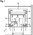
- FIG. 1 Based on FIG. 1 a barrier system 2 according to the invention with the filter units 1 according to the invention is presented.
- the barrier system 2 has a hermetically sealed processing space 4.
- this processing space 4 is a filling machine 5 for liquid or powdered medicines.
- the medicines are bottled in a container 6.
- Not shown are inlet and outlet locks, for example, for the containers 6.
- a return air duct 3a is formed between a glass double disc.
- the return air duct 3b could also be designed differently, as an alternative to the glass double-pane, e.g. as a separate sheet metal construction.
- the return air ducts 3a, 3b lead from the filter unit 1 into a further unit, for example into an LF unit 13.
- the arrows shown in bold represent an air flow 8 in the barrier system 2.
- the air flow 8 leads from an air outlet side 10 of the filter units 1 via the return air ducts 3 a, 3 b to an LF unit 13.
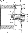
- FIG. 2 shows the filter unit 1 according to a first embodiment.
- the exchangeable filter unit 1 comprises a filter 20, which is exemplified in the exemplary embodiment as a cylindrical cartridge.
- the filter 20 is fixedly connected to a filter closure 22.
- the filter closure 22 consists of a tubular part and serves partly as unspecified cylindrical support surface in the axial direction for the circular end face of the filter 20. At the same time covers the filter closure 22 in the axial direction, the upper outer side of the filter 20 by a slightly larger inner radius.
- the filter closure 22 comprises a piston receptacle 26, which is connected by a fastening 28 with the filter closure 22.
- the axis of the piston receptacle 26 is oriented substantially parallel to the direction of movement of a cover 40.
- connection 30 for a line 32 is provided on the front side of the piston seat 26, a connection 30 for a line 32 is provided.
- the line 32 extends through the interior of the filter 20 and is guided radially through the lateral surface of the filter closure 22 to the outside to an outer terminal 33.
- the exchangeable filter unit 1 can be connected to a main line arranged on the housing of the barrier system 2.
- the piston receptacle 26 serves to guide a piston 34.
- a piston guide 36 is provided, for example in the form of a piston guide ring 36.
- at least one seal 48 is arranged between piston 34 and piston receptacle 26, preferably two seals 48 in the form of piston seal rings.
- piston guide and / or piston seal could be integrated directly in the piston 34, in particular in a plastic injection molded part.
- the piston receptacle 26 encloses the piston 34 at least partially in these areas.
- the piston 34 is biased relative to the piston seat 26 by a compression spring 38 in the axial direction.
- the spring 38 is supported on the closed end face of the piston 34 and the opposite end face of the piston seat 26 from.
- the piston 34 is opened, closed on the side facing away from the terminal 30.
- the piston 34 is connected at the side facing away from the piston seat 26 side with the cover 40 or part of the lid 40.
- the cover 40 has a substantially circular structure.
- the middle region of the cover 40 projects beyond the edge region of the cover 40, namely in the opposite direction to the filter 20.
- the piston 34 is at least partially arranged, so that the filter closure 22 can be made relatively narrow .
- the side facing away from the filter 20 side of the lid 40 covers in the closed state, as in FIG. 2 shown, sealing and flush an opening 50 on the inside of the filter flange 24th
- a closure seal 46 is provided, which is arranged between the filter flange 24 and the outside of the lid 40.
- the closure seal 46 could be inserted in a groove on the cover 40.
- the filter flange 24 On the outside, that is on the filter 20 facing away from the side, the filter flange 24 has an outer flange seal 42 and an inner flange seal 44.
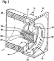
- FIG. 3 is the in FIG. 2 shown filter unit 1 shown in the open state.
- the arrows 18, the air duct is indicated.
- the air passes through the opening 50 below the lid 40 into the interior of the filter unit 1 and flows through the filter 20 through to the return air ducts 3 on.
- This illustration can also be seen that in the open state, the piston 34 abuts on the end face of the piston seat 26.
- a negative pressure is generated via the line 32 and the port 30, which sucks the piston 34 and the cover 40 connected thereto to the end face of the piston receiving means 26.
- the force generated in this case is greater than the spring force of the compression spring 38, so that a movement takes place counter to the spring force.
- the compression spring 38 is preloaded or compressed.
- the spring 38 would bring the cover 40 in the closed state.
- no undefined open states of the filter unit 1 can occur in the event of an error.
- the inner sides of the piston 34 and piston receptacle 26 form a pressure chamber 31. The pressure conditions in this pressure chamber 31, the relative movement between the piston 34 and the piston seat 26 can be controlled.
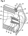
- the embodiment according to the FIGS. 4 and 5 differs from the one after the Figures 2 and 3 in that the cover 40 covers the side facing away from the filter 20 of the flange 24.
- the opening 50 is now closed by the filter 20 toward the oriented inside of the lid 40.
- the cover 40 away from the filter 20 and the flange 24.
- the peculiarity of this embodiment lies in a minimized depth of the filter flange 24 and the filter closure 22.
- the piston 34 when mounted with a shaft 41 of the lid 40th firmly connected, such as by screwing or gluing.
- the piston 40 is sleeve-shaped and surrounds with an inner ring 43 on the one hand, the cylindrical shaft 41 of the lid 40 to create a solid connection.
- the piston 40 On the side remote from the cover 40, the piston 40 has a closed bottom 47 with a larger radius than the inner ring 43. Extending axially from the outside of the bottom 47 in the direction of the cover 40 is an outer ring 45, which in the open state according to FIG. 4 with a projection 27 of the piston seat 26 cooperates.
- the piston receptacle 26 has on the side facing the filter 20 on a region of larger diameter, in which the ring 45 of the piston 26 is guided. After the stepped projection 27, the diameter of the piston receptacle 26 is smaller, so that the projection 27 can serve as a bearing surface for the end face of the outer ring 45.
- a seal or a stop 37 may be arranged to seal the interior of the piston seat 26 with respect to the interior of the filter 20 or as a defined stop surface between the piston 34 and the piston seat 26.
- a spring 38 is arranged between the inner ring 43, the outer ring 45th and the piston receiver 26.
- the conduit 32 opens radially in that region of the piston receiver 26 with a smaller diameter in the intermediate space in which the spring 38 is arranged.
- This intermediate space acts as a pressure chamber 31, so that its pressure conditions, the movement of the piston 34 (and thus the lid 40) relative to the receptacle 26 can be controlled.
- the influence of the pressure can be done for example hydraulically or pneumatically.
- the embodiment according to the FIGS. 6 or 7 is in principle similar to the one after the Figures 2 and 3 , It differs in that now several openings 50 are provided in the flange 24. For example, they can be fan-shaped. Also in the center region of the lid 40, a circular opening 50 is provided on the flange. About the single cover 40, the five openings 50 can now be closed. For this purpose, the shape of the lid 40 corresponds to those of the openings 50 to be closed. In any case, the lid shape is selected so that all openings 50 can be securely closed.
- FIG. 7 shows the opened state. Also facing away from the filter 20 end face of the piston 34 is able to close the central opening 50.
- the lid 40 which closes the remaining four openings 50, is also connected to the piston 34.
- the piston receptacle 26 is in turn fixedly connected to the filter closure 22 or filter flange 24 via the attachment 28.
- the shape of the cover 40 thus differs correspondingly and has a direct influence on the inflow conditions of the medium to be filtered in the filter unit 1. Furthermore, this embodiment is characterized by a small overall depth of the filter flange 24.
- the filter unit 1 is designed as a return air filter, which is arranged directly in the opening of the return air duct 3, to allow a gas-tight and easy-to-use clamping against the housing to be vacuumed in the processing space 4.
- the filter unit 1 further comprises the filter 20 with a tight, resealable cover 40 on the unfiltered air side or air inlet side 9.
- the cover 40 is designed so that it closes spring-actuated and the filter unit 1 by an integrated seal 46 seals roohluft devis. The contaminated side or the contaminated volume in the Filter unit 1 can thus be securely encapsulated.
- the entire processing space 4 and the processing space 4 facing side of the lid 40 to clean before the barrier system 2 can be opened.
- the complete filter unit 1 is to be replaced.
- the filter unit 1 is only to dismantle from the housing and possibly to secure.
- the security can be further increased by packing the filter unit 1 after removal, for example, in a protective film or a container. Subsequently, the new filter unit 1 can be mounted.
- the piston receptacle 26 is preferably designed pressure-tight relative to the interior of the filter unit 1 and forms the pressure chamber 31. This ensure corresponding seals 48, which are arranged between the piston 34 and the piston seat 26. About the pressure conditions in this pressure chamber 31, the movement of the piston 34 can be controlled relative to the piston seat 26.
- the connection 30 is provided on the pressure chamber 31. Via the connection 30, the line 32 opens into the pressure chamber 31 via these at least one line 32, the pressure conditions in the pressure chamber 31 can be influenced. The line 32 is guided to the outside of the filter unit 1.
- Piston 34 and piston seat 26 may be formed, for example, cylindrical. In principle, however, other forms are conceivable.
- the cover 40 is moved.
- the piston 34 is connected to the cover 40 for this purpose.
- the piston guide 26 could be connected to the cover 40, while the piston 34 is fixedly connected to the filter closure 22, the filter flange 24 and the filter 20. It is essential in any case that the piston 34 and the piston seat 26 are arranged in the interior of the interchangeable filter unit 1 as integral components.
- the outer interface 33 is provided as the only interface as a connection to a main line.
- piston 34 and piston seat 26 can be generated in different ways. It would be conceivable, for example, the use of a hydraulic unit, so that would be provided as a line 32, a hydraulic line. Also could be worked with under or over pressure.
- the movement of the lid 40 relative to the openings 50 could be done in other ways.
- further openings could be provided in the cover 40, which are brought by rotation in coincidence with the openings 50 for passage of the air flow 18, while closing the openings 50 could be covered by closed sections of the cover 40.
- a superposition of rotary and lifting movement could be considered.
- piston 34 and piston guide 36 could communicate with each other via a thread principle. For example, upon rotation on the cover 40, this makes an axial movement.
- the filter closure 22 comprises the filter flange 24, via which the connection with a housing or the like, in particular of a barrier system 2, can be produced.
- a housing or the like in particular of a barrier system 2
- recordings for screws or other fasteners are provided.
- the filter device 1 is particularly suitable for the use of barrier systems 1 for, for example, clean rooms, isolators, containment systems or so-called cRABS (closed Restricted Access Barrier System).
- barrier systems 1 for, for example, clean rooms, isolators, containment systems or so-called cRABS (closed Restricted Access Barrier System).
- cRABS closed Restricted Access Barrier System
Landscapes
- Chemical & Material Sciences (AREA)
- Chemical Kinetics & Catalysis (AREA)
- Physics & Mathematics (AREA)
- Geometry (AREA)
- Health & Medical Sciences (AREA)
- Engineering & Computer Science (AREA)
- Environmental & Geological Engineering (AREA)
- Toxicology (AREA)
- Filtering Of Dispersed Particles In Gases (AREA)
Claims (13)
- Unité de filtration (1) à utiliser dans un canal d'air de retour ou d'évacuation d'air (3) d'un système de barrière (2), comprenant un obturateur de filtre (22) pour l'assemblage de l'unité de filtration (1) à un système de barrière (2), dans laquelle l'obturateur de filtre (22) présente au moins une bride de filtre (24) avec au moins une ouverture (50),- un moyen de filtration (20) assemblé techniquement en écoulement à l'obturateur de filtre (22) pour l'épuration de l'air envoyé par l'ouverture (50) à partir d'une chambre de traitement du système de barrière (2) et pour la décharge dans le canal d'air de retour ou d'évacuation d'air (3),- au moins un couvercle (40) pour ouvrir et fermer l'ouverture (50), l'unité de filtration (1) présentant une chambre intérieure pouvant être fermée au moyen du couvercle (40) pour entourer des substances dangereuses,caractérisée en ce que l'unité de filtration (1) comprend, pour le déplacement du couvercle (40) à l'intérieur au moins un logement de piston (34) et un piston (34) mobile par rapport à celui-ci, qui est monté de façon mobile dans le logement de piston (26), et en ce que le logement (26) et le piston (34) sont précontraints l'un par rapport à l'autre au moyen d'un ressort, de préférence un ressort de pression (38).
- Unité de filtration selon la revendication 1, caractérisée en ce qu'il est prévu au moins une conduite (32) à l'intérieur de l'unité de filtration (1) pour influencer le mouvement relatif entre le piston (34) et le logement de piston (26).
- Unité de filtration selon l'une quelconque des revendications précédentes, caractérisée en ce que le logement de piston (26) comporte au moins un raccord (30), par lequel la conduite (32) est raccordée au logement de piston (26).
- Unité de filtration selon l'une quelconque des revendications précédentes, comprenant au moins un raccord extérieur (33), par lequel la conduite (32) peut être raccordée à l'intérieur de l'unité de filtration (1) à une conduite principale dans l'isolateur (2) ou la chambre propre pour influencer le mouvement relatif entre le piston (34) et le logement de piston (26).
- Unité de filtration selon l'une quelconque des revendications précédentes, caractérisée en ce que le logement de piston (26) est assemblé à l'obturateur de filtre (22) et/ou à la bride de filtre (24) par une fixation (28).
- Unité de filtration selon l'une quelconque des revendications précédentes, caractérisée en ce qu'au moins un joint d'étanchéité (48) et/ou un guidage de piston (36) sont disposés entre le piston (34) et le logement de piston (26).
- Unité de filtration selon l'une quelconque des revendications précédentes, caractérisée en ce que le logement de piston (26) ou le piston (34) est relié au couvercle (40).
- Unité de filtration selon l'une quelconque des revendications précédentes, caractérisée en ce que le couvercle (40) ferme l'ouverture (50) avec son côté tourné vers le moyen de filtration (20).
- Unité de filtration selon l'une quelconque des revendications précédentes, caractérisée en ce que le couvercle (40) ferme l'ouverture (50) avec son côté détourné du moyen de filtration (20).
- Unité de filtration selon l'une quelconque des revendications précédentes, caractérisée en ce qu'au moins un joint d'étanchéité de fermeture (46) est disposé sur la bride de filtre (24).
- Unité de filtration selon l'une quelconque des revendications précédentes, caractérisée en ce que pour le mouvement du piston (34), on opère un actionnement électrique, hydraulique ou pneumatique sur le logement (26) .
- Unité de filtration selon l'une quelconque des revendications précédentes, caractérisée en ce que le couvercle (40) est actionné en un mouvement de levée et/ou en un mouvement de rotation pour fermer l'ouverture (50).
- Unité de filtration selon l'une quelconque des revendications précédentes, caractérisée en ce qu'il est prévu plusieurs ouvertures (50), que le couvercle (40) ferme au moins en partie.
Applications Claiming Priority (1)
| Application Number | Priority Date | Filing Date | Title |
|---|---|---|---|
| DE102012208574A DE102012208574A1 (de) | 2012-05-22 | 2012-05-22 | Filtereinheit für ein Barrieresystem |
Publications (3)
| Publication Number | Publication Date |
|---|---|
| EP2666532A1 EP2666532A1 (fr) | 2013-11-27 |
| EP2666532B1 EP2666532B1 (fr) | 2017-03-01 |
| EP2666532B2 true EP2666532B2 (fr) | 2019-11-13 |
Family
ID=48044611
Family Applications (1)
| Application Number | Title | Priority Date | Filing Date |
|---|---|---|---|
| EP13161197.2A Active EP2666532B2 (fr) | 2012-05-22 | 2013-03-26 | Unité de filtration pour un système de barrière |
Country Status (3)
| Country | Link |
|---|---|
| EP (1) | EP2666532B2 (fr) |
| CN (1) | CN103418190B (fr) |
| DE (1) | DE102012208574A1 (fr) |
Families Citing this family (4)
| Publication number | Priority date | Publication date | Assignee | Title |
|---|---|---|---|---|
| EP3170545B1 (fr) * | 2015-11-23 | 2019-12-25 | Skan Ag | Systeme de filtre pour une enceinte de confinement traversee par un flux de gaz |
| DE102017126228B3 (de) | 2017-11-09 | 2019-01-31 | Metall + Plastic Gmbh | Filtereinheit für ein Barrieresystem sowie Barrieresystem, insbesondere Isolator |
| WO2019233892A1 (fr) | 2018-06-07 | 2019-12-12 | Metall + Plastic Gmbh | Système de fermeture, unité filtrante pour un système de barrière, et système de barrière, en particulier isolateur |
| EP3834937A1 (fr) | 2019-12-10 | 2021-06-16 | Skan Ag | Structure d'un confinement dotée d'une chambre de travail aseptique |
Citations (1)
| Publication number | Priority date | Publication date | Assignee | Title |
|---|---|---|---|---|
| DE4216102C1 (en) † | 1992-05-15 | 1993-07-08 | Bissinger Gmbh, 7129 Zaberfeld, De | Good internal cleaning of tubular filter cartridge - using narrow central jet of compressed air, providing cleaning of filter even during operation |
Family Cites Families (8)
| Publication number | Priority date | Publication date | Assignee | Title |
|---|---|---|---|---|
| US4045349A (en) * | 1976-07-09 | 1977-08-30 | Wix Corporation | Filter with multiple attaching means |
| US4266955A (en) | 1977-05-31 | 1981-05-12 | United Kingdom Atomic Energy Authority | Particle-in-gas filtration |
| US4497706A (en) * | 1983-11-02 | 1985-02-05 | Purolator Inc. | Oil filter relief valve |
| IT1298378B1 (it) * | 1997-12-19 | 2000-01-05 | Chiara Perazzo | Filtro disoleatore, con associata valvola di minima pressione per impianti erogatori di aria compressa. |
| DE19947781C1 (de) | 1999-10-02 | 2000-12-21 | Bosch Gmbh Robert | Verfahren und Vorrichtung zur Luftführung in einem Bearbeitungsraum |
| DE50301399D1 (de) * | 2002-07-16 | 2006-03-02 | Mann & Hummel Gmbh | Ventil zur Steuerung eines Fluidstromes |
| CH700390A1 (de) | 2009-02-05 | 2010-08-13 | Skan Ag | Filtervorrichtung für eine von einem Gasstrom durchflossene Anlage mit einer Arbeitskammer zur temporären Aufnahme von Behandlungsgut. |
| CN101632887B (zh) * | 2009-08-20 | 2011-08-10 | 武汉凯迪电力股份有限公司 | 复合活塞式脉冲电磁阀 |
-
2012
- 2012-05-22 DE DE102012208574A patent/DE102012208574A1/de not_active Withdrawn
-
2013
- 2013-03-26 EP EP13161197.2A patent/EP2666532B2/fr active Active
- 2013-05-22 CN CN201310192377.7A patent/CN103418190B/zh active Active
Patent Citations (1)
| Publication number | Priority date | Publication date | Assignee | Title |
|---|---|---|---|---|
| DE4216102C1 (en) † | 1992-05-15 | 1993-07-08 | Bissinger Gmbh, 7129 Zaberfeld, De | Good internal cleaning of tubular filter cartridge - using narrow central jet of compressed air, providing cleaning of filter even during operation |
Also Published As
| Publication number | Publication date |
|---|---|
| DE102012208574A1 (de) | 2013-11-28 |
| EP2666532B1 (fr) | 2017-03-01 |
| CN103418190A (zh) | 2013-12-04 |
| CN103418190B (zh) | 2017-04-26 |
| EP2666532A1 (fr) | 2013-11-27 |
Similar Documents
| Publication | Publication Date | Title |
|---|---|---|
| EP0521252B1 (fr) | Machine de remplissage pour des produits granuleux ou liquides de nature dangereuse | |
| EP3146881B1 (fr) | Nettoyage de filtre pour aspirateur | |
| EP0916046B1 (fr) | Soupape a siege double | |
| DE2755964C2 (de) | Filteranordnung zur Abscheidung toxischer oder radioaktiver Stoffe aus der Atem- oder Prozeßluft, insbesondere von kerntechnischen Anlagen | |
| EP0588070B1 (fr) | Buse de remplissage et soutirage de sécurité adaptée à des matières liquides, pâteuses et pulvérulentes | |
| EP2666532B2 (fr) | Unité de filtration pour un système de barrière | |
| EP3170545B1 (fr) | Systeme de filtre pour une enceinte de confinement traversee par un flux de gaz | |
| EP1603679A1 (fr) | Centrifugeuse a filtre de recouvrement | |
| DE102014009231A1 (de) | Absperr-Filtervorrichtung | |
| DE19949095A1 (de) | Filterabreinigung in einem Schmutzsauger | |
| DE2050598C3 (de) | Vorrichtung zum Durchschleusen radioaktiv kontaminierter Flüssigkeiten und/oder Gase | |
| DE202010017347U1 (de) | Filtervorrichtung für eine von einem gasstrom durchflossene anlage mit einer arbeitskammer zur temporären aufnahme von behandlungsgut | |
| EP3573502B1 (fr) | Fermeture de gourde, en particulier pour une bouteille isolante | |
| EP3371019A1 (fr) | Soupape de limitation de pression | |
| DE4110996A1 (de) | Rohrweiche und dichtungsanordnung hierfuer | |
| EP0305821A1 (fr) | Dispositif pour fermer l'embranchement d'un tube | |
| EP1213244B1 (fr) | Dispositif d'accouplement à deux plaques | |
| DE3516128C2 (fr) | ||
| DE102019121594A1 (de) | Anschlussvorrichtung | |
| DE102012009207A1 (de) | Füllelement | |
| DE102013110292B4 (de) | Vorrichtung zum Koppeln von zwei Behältern | |
| DE102008017768A1 (de) | Sperreinrichtung zwischen einem unsterilen Bereich und einem sterilen Bereich | |
| DE19753185A1 (de) | Transportbox | |
| EP2886474B1 (fr) | Dispositif d'emballage sans contamination de produits dans des sacs tubulaires et utilisation du dispositif | |
| EP1852189A2 (fr) | Concept d'installation pour moulin et séparation à entraînement de broche de palier magnétique |
Legal Events
| Date | Code | Title | Description |
|---|---|---|---|
| PUAI | Public reference made under article 153(3) epc to a published international application that has entered the european phase |
Free format text: ORIGINAL CODE: 0009012 |
|
| AK | Designated contracting states |
Kind code of ref document: A1 Designated state(s): AL AT BE BG CH CY CZ DE DK EE ES FI FR GB GR HR HU IE IS IT LI LT LU LV MC MK MT NL NO PL PT RO RS SE SI SK SM TR |
|
| AX | Request for extension of the european patent |
Extension state: BA ME |
|
| 17P | Request for examination filed |
Effective date: 20140527 |
|
| RBV | Designated contracting states (corrected) |
Designated state(s): AL AT BE BG CH CY CZ DE DK EE ES FI FR GB GR HR HU IE IS IT LI LT LU LV MC MK MT NL NO PL PT RO RS SE SI SK SM TR |
|
| 17Q | First examination report despatched |
Effective date: 20160219 |
|
| GRAP | Despatch of communication of intention to grant a patent |
Free format text: ORIGINAL CODE: EPIDOSNIGR1 |
|
| INTG | Intention to grant announced |
Effective date: 20161118 |
|
| GRAS | Grant fee paid |
Free format text: ORIGINAL CODE: EPIDOSNIGR3 |
|
| GRAA | (expected) grant |
Free format text: ORIGINAL CODE: 0009210 |
|
| AK | Designated contracting states |
Kind code of ref document: B1 Designated state(s): AL AT BE BG CH CY CZ DE DK EE ES FI FR GB GR HR HU IE IS IT LI LT LU LV MC MK MT NL NO PL PT RO RS SE SI SK SM TR |
|
| REG | Reference to a national code |
Ref country code: GB Ref legal event code: FG4D Free format text: NOT ENGLISH |
|
| REG | Reference to a national code |
Ref country code: CH Ref legal event code: EP Ref country code: AT Ref legal event code: REF Ref document number: 870612 Country of ref document: AT Kind code of ref document: T Effective date: 20170315 |
|
| REG | Reference to a national code |
Ref country code: IE Ref legal event code: FG4D Free format text: LANGUAGE OF EP DOCUMENT: GERMAN |
|
| REG | Reference to a national code |
Ref country code: DE Ref legal event code: R096 Ref document number: 502013006490 Country of ref document: DE |
|
| REG | Reference to a national code |
Ref country code: FR Ref legal event code: PLFP Year of fee payment: 5 |
|
| REG | Reference to a national code |
Ref country code: NL Ref legal event code: MP Effective date: 20170301 |
|
| REG | Reference to a national code |
Ref country code: LT Ref legal event code: MG4D |
|
| PG25 | Lapsed in a contracting state [announced via postgrant information from national office to epo] |
Ref country code: HR Free format text: LAPSE BECAUSE OF FAILURE TO SUBMIT A TRANSLATION OF THE DESCRIPTION OR TO PAY THE FEE WITHIN THE PRESCRIBED TIME-LIMIT Effective date: 20170301 Ref country code: GR Free format text: LAPSE BECAUSE OF FAILURE TO SUBMIT A TRANSLATION OF THE DESCRIPTION OR TO PAY THE FEE WITHIN THE PRESCRIBED TIME-LIMIT Effective date: 20170602 Ref country code: NO Free format text: LAPSE BECAUSE OF FAILURE TO SUBMIT A TRANSLATION OF THE DESCRIPTION OR TO PAY THE FEE WITHIN THE PRESCRIBED TIME-LIMIT Effective date: 20170601 Ref country code: LT Free format text: LAPSE BECAUSE OF FAILURE TO SUBMIT A TRANSLATION OF THE DESCRIPTION OR TO PAY THE FEE WITHIN THE PRESCRIBED TIME-LIMIT Effective date: 20170301 Ref country code: FI Free format text: LAPSE BECAUSE OF FAILURE TO SUBMIT A TRANSLATION OF THE DESCRIPTION OR TO PAY THE FEE WITHIN THE PRESCRIBED TIME-LIMIT Effective date: 20170301 |
|
| PG25 | Lapsed in a contracting state [announced via postgrant information from national office to epo] |
Ref country code: SE Free format text: LAPSE BECAUSE OF FAILURE TO SUBMIT A TRANSLATION OF THE DESCRIPTION OR TO PAY THE FEE WITHIN THE PRESCRIBED TIME-LIMIT Effective date: 20170301 Ref country code: LV Free format text: LAPSE BECAUSE OF FAILURE TO SUBMIT A TRANSLATION OF THE DESCRIPTION OR TO PAY THE FEE WITHIN THE PRESCRIBED TIME-LIMIT Effective date: 20170301 Ref country code: RS Free format text: LAPSE BECAUSE OF FAILURE TO SUBMIT A TRANSLATION OF THE DESCRIPTION OR TO PAY THE FEE WITHIN THE PRESCRIBED TIME-LIMIT Effective date: 20170301 Ref country code: BG Free format text: LAPSE BECAUSE OF FAILURE TO SUBMIT A TRANSLATION OF THE DESCRIPTION OR TO PAY THE FEE WITHIN THE PRESCRIBED TIME-LIMIT Effective date: 20170601 Ref country code: ES Free format text: LAPSE BECAUSE OF FAILURE TO SUBMIT A TRANSLATION OF THE DESCRIPTION OR TO PAY THE FEE WITHIN THE PRESCRIBED TIME-LIMIT Effective date: 20170301 |
|
| PG25 | Lapsed in a contracting state [announced via postgrant information from national office to epo] |
Ref country code: NL Free format text: LAPSE BECAUSE OF FAILURE TO SUBMIT A TRANSLATION OF THE DESCRIPTION OR TO PAY THE FEE WITHIN THE PRESCRIBED TIME-LIMIT Effective date: 20170301 |
|
| PG25 | Lapsed in a contracting state [announced via postgrant information from national office to epo] |
Ref country code: RO Free format text: LAPSE BECAUSE OF FAILURE TO SUBMIT A TRANSLATION OF THE DESCRIPTION OR TO PAY THE FEE WITHIN THE PRESCRIBED TIME-LIMIT Effective date: 20170301 Ref country code: EE Free format text: LAPSE BECAUSE OF FAILURE TO SUBMIT A TRANSLATION OF THE DESCRIPTION OR TO PAY THE FEE WITHIN THE PRESCRIBED TIME-LIMIT Effective date: 20170301 Ref country code: CZ Free format text: LAPSE BECAUSE OF FAILURE TO SUBMIT A TRANSLATION OF THE DESCRIPTION OR TO PAY THE FEE WITHIN THE PRESCRIBED TIME-LIMIT Effective date: 20170301 Ref country code: SK Free format text: LAPSE BECAUSE OF FAILURE TO SUBMIT A TRANSLATION OF THE DESCRIPTION OR TO PAY THE FEE WITHIN THE PRESCRIBED TIME-LIMIT Effective date: 20170301 |
|
| PG25 | Lapsed in a contracting state [announced via postgrant information from national office to epo] |
Ref country code: PL Free format text: LAPSE BECAUSE OF FAILURE TO SUBMIT A TRANSLATION OF THE DESCRIPTION OR TO PAY THE FEE WITHIN THE PRESCRIBED TIME-LIMIT Effective date: 20170301 Ref country code: PT Free format text: LAPSE BECAUSE OF FAILURE TO SUBMIT A TRANSLATION OF THE DESCRIPTION OR TO PAY THE FEE WITHIN THE PRESCRIBED TIME-LIMIT Effective date: 20170703 Ref country code: IS Free format text: LAPSE BECAUSE OF FAILURE TO SUBMIT A TRANSLATION OF THE DESCRIPTION OR TO PAY THE FEE WITHIN THE PRESCRIBED TIME-LIMIT Effective date: 20170701 Ref country code: SM Free format text: LAPSE BECAUSE OF FAILURE TO SUBMIT A TRANSLATION OF THE DESCRIPTION OR TO PAY THE FEE WITHIN THE PRESCRIBED TIME-LIMIT Effective date: 20170301 |
|
| REG | Reference to a national code |
Ref country code: DE Ref legal event code: R026 Ref document number: 502013006490 Country of ref document: DE |
|
| PLBI | Opposition filed |
Free format text: ORIGINAL CODE: 0009260 |
|
| PLAX | Notice of opposition and request to file observation + time limit sent |
Free format text: ORIGINAL CODE: EPIDOSNOBS2 |
|
| REG | Reference to a national code |
Ref country code: IE Ref legal event code: MM4A |
|
| 26 | Opposition filed |
Opponent name: SKAN AG Effective date: 20171201 |
|
| PG25 | Lapsed in a contracting state [announced via postgrant information from national office to epo] |
Ref country code: MC Free format text: LAPSE BECAUSE OF FAILURE TO SUBMIT A TRANSLATION OF THE DESCRIPTION OR TO PAY THE FEE WITHIN THE PRESCRIBED TIME-LIMIT Effective date: 20170301 Ref country code: LU Free format text: LAPSE BECAUSE OF NON-PAYMENT OF DUE FEES Effective date: 20170326 Ref country code: DK Free format text: LAPSE BECAUSE OF FAILURE TO SUBMIT A TRANSLATION OF THE DESCRIPTION OR TO PAY THE FEE WITHIN THE PRESCRIBED TIME-LIMIT Effective date: 20170301 |
|
| GBPC | Gb: european patent ceased through non-payment of renewal fee |
Effective date: 20170601 |
|
| PG25 | Lapsed in a contracting state [announced via postgrant information from national office to epo] |
Ref country code: SI Free format text: LAPSE BECAUSE OF FAILURE TO SUBMIT A TRANSLATION OF THE DESCRIPTION OR TO PAY THE FEE WITHIN THE PRESCRIBED TIME-LIMIT Effective date: 20170301 Ref country code: IE Free format text: LAPSE BECAUSE OF NON-PAYMENT OF DUE FEES Effective date: 20170326 |
|
| REG | Reference to a national code |
Ref country code: BE Ref legal event code: MM Effective date: 20170331 |
|
| PLBB | Reply of patent proprietor to notice(s) of opposition received |
Free format text: ORIGINAL CODE: EPIDOSNOBS3 |
|
| REG | Reference to a national code |
Ref country code: FR Ref legal event code: PLFP Year of fee payment: 6 |
|
| PG25 | Lapsed in a contracting state [announced via postgrant information from national office to epo] |
Ref country code: GB Free format text: LAPSE BECAUSE OF NON-PAYMENT OF DUE FEES Effective date: 20170601 |
|
| PG25 | Lapsed in a contracting state [announced via postgrant information from national office to epo] |
Ref country code: BE Free format text: LAPSE BECAUSE OF NON-PAYMENT OF DUE FEES Effective date: 20170331 |
|
| PG25 | Lapsed in a contracting state [announced via postgrant information from national office to epo] |
Ref country code: MT Free format text: LAPSE BECAUSE OF FAILURE TO SUBMIT A TRANSLATION OF THE DESCRIPTION OR TO PAY THE FEE WITHIN THE PRESCRIBED TIME-LIMIT Effective date: 20170301 |
|
| REG | Reference to a national code |
Ref country code: AT Ref legal event code: MM01 Ref document number: 870612 Country of ref document: AT Kind code of ref document: T Effective date: 20180326 |
|
| PG25 | Lapsed in a contracting state [announced via postgrant information from national office to epo] |
Ref country code: HU Free format text: LAPSE BECAUSE OF FAILURE TO SUBMIT A TRANSLATION OF THE DESCRIPTION OR TO PAY THE FEE WITHIN THE PRESCRIBED TIME-LIMIT; INVALID AB INITIO Effective date: 20130326 |
|
| PUAH | Patent maintained in amended form |
Free format text: ORIGINAL CODE: 0009272 |
|
| STAA | Information on the status of an ep patent application or granted ep patent |
Free format text: STATUS: PATENT MAINTAINED AS AMENDED |
|
| PG25 | Lapsed in a contracting state [announced via postgrant information from national office to epo] |
Ref country code: AT Free format text: LAPSE BECAUSE OF NON-PAYMENT OF DUE FEES Effective date: 20180326 Ref country code: CY Free format text: LAPSE BECAUSE OF NON-PAYMENT OF DUE FEES Effective date: 20170301 |
|
| REG | Reference to a national code |
Ref country code: CH Ref legal event code: AELC |
|
| 27A | Patent maintained in amended form |
Effective date: 20191113 |
|
| AK | Designated contracting states |
Kind code of ref document: B2 Designated state(s): AL AT BE BG CH CY CZ DE DK EE ES FI FR GB GR HR HU IE IS IT LI LT LU LV MC MK MT NL NO PL PT RO RS SE SI SK SM TR |
|
| REG | Reference to a national code |
Ref country code: DE Ref legal event code: R102 Ref document number: 502013006490 Country of ref document: DE |
|
| PG25 | Lapsed in a contracting state [announced via postgrant information from national office to epo] |
Ref country code: MK Free format text: LAPSE BECAUSE OF FAILURE TO SUBMIT A TRANSLATION OF THE DESCRIPTION OR TO PAY THE FEE WITHIN THE PRESCRIBED TIME-LIMIT Effective date: 20170301 |
|
| PG25 | Lapsed in a contracting state [announced via postgrant information from national office to epo] |
Ref country code: TR Free format text: LAPSE BECAUSE OF FAILURE TO SUBMIT A TRANSLATION OF THE DESCRIPTION OR TO PAY THE FEE WITHIN THE PRESCRIBED TIME-LIMIT Effective date: 20170301 |
|
| REG | Reference to a national code |
Ref country code: DE Ref legal event code: R082 Ref document number: 502013006490 Country of ref document: DE Representative=s name: DREISS PATENTANWAELTE PARTG MBB, DE Ref country code: DE Ref legal event code: R081 Ref document number: 502013006490 Country of ref document: DE Owner name: SYNTEGON TECHNOLOGY GMBH, DE Free format text: FORMER OWNER: ROBERT BOSCH PACKAGING TECHNOLOGY GMBH, 71332 WAIBLINGEN, DE Ref country code: DE Ref legal event code: R081 Ref document number: 502013006490 Country of ref document: DE Owner name: SYNTEGON TECHNOLOGY GMBH, DE Free format text: FORMER OWNER: ROBERT BOSCH GMBH, 70469 STUTTGART, DE |
|
| PG25 | Lapsed in a contracting state [announced via postgrant information from national office to epo] |
Ref country code: AL Free format text: LAPSE BECAUSE OF FAILURE TO SUBMIT A TRANSLATION OF THE DESCRIPTION OR TO PAY THE FEE WITHIN THE PRESCRIBED TIME-LIMIT Effective date: 20170301 |
|
| REG | Reference to a national code |
Ref country code: CH Ref legal event code: PUE Owner name: SYNTEGON TECHNOLOGY GMBH, DE Free format text: FORMER OWNER: ROBERT BOSCH GMBH, DE |
|
| PGFP | Annual fee paid to national office [announced via postgrant information from national office to epo] |
Ref country code: IT Payment date: 20250331 Year of fee payment: 13 |
|
| PGFP | Annual fee paid to national office [announced via postgrant information from national office to epo] |
Ref country code: CH Payment date: 20250401 Year of fee payment: 13 |
|
| REG | Reference to a national code |
Ref country code: DE Ref legal event code: R081 Ref document number: 502013006490 Country of ref document: DE Owner name: SYNTEGON TECHNOLOGY GMBH, DE Free format text: FORMER OWNER: SYNTEGON TECHNOLOGY GMBH, 71332 WAIBLINGEN, DE |
|
| REG | Reference to a national code |
Ref country code: CH Ref legal event code: R18 Free format text: ST27 STATUS EVENT CODE: U-0-0-R10-R18 (AS PROVIDED BY THE NATIONAL OFFICE) Effective date: 20260213 |
|
| REG | Reference to a national code |
Ref country code: CH Ref legal event code: U11 Free format text: ST27 STATUS EVENT CODE: U-0-0-U10-U11 (AS PROVIDED BY THE NATIONAL OFFICE) Effective date: 20260401 |
|
| PGFP | Annual fee paid to national office [announced via postgrant information from national office to epo] |
Ref country code: DE Payment date: 20260320 Year of fee payment: 14 |
|
| PGFP | Annual fee paid to national office [announced via postgrant information from national office to epo] |
Ref country code: FR Payment date: 20260324 Year of fee payment: 14 |