EP2666697A1 - Verfahren zur Bestimmung des Durchmessers eines Rads, und entsprechendes Bestimmungsmittel - Google Patents
Verfahren zur Bestimmung des Durchmessers eines Rads, und entsprechendes Bestimmungsmittel Download PDFInfo
- Publication number
- EP2666697A1 EP2666697A1 EP13168736.0A EP13168736A EP2666697A1 EP 2666697 A1 EP2666697 A1 EP 2666697A1 EP 13168736 A EP13168736 A EP 13168736A EP 2666697 A1 EP2666697 A1 EP 2666697A1
- Authority
- EP
- European Patent Office
- Prior art keywords
- vehicle
- wheel
- acceleration
- magnitude
- diameter
- Prior art date
- Legal status (The legal status is an assumption and is not a legal conclusion. Google has not performed a legal analysis and makes no representation as to the accuracy of the status listed.)
- Granted
Links
Images


Classifications
-
- G—PHYSICS
- G01—MEASURING; TESTING
- G01B—MEASURING LENGTH, THICKNESS OR SIMILAR LINEAR DIMENSIONS; MEASURING ANGLES; MEASURING AREAS; MEASURING IRREGULARITIES OF SURFACES OR CONTOURS
- G01B21/00—Measuring arrangements or details thereof, where the measuring technique is not covered by the other groups of this subclass, unspecified or not relevant
- G01B21/10—Measuring arrangements or details thereof, where the measuring technique is not covered by the other groups of this subclass, unspecified or not relevant for measuring diameters
- G01B21/12—Measuring arrangements or details thereof, where the measuring technique is not covered by the other groups of this subclass, unspecified or not relevant for measuring diameters of objects while moving
-
- B—PERFORMING OPERATIONS; TRANSPORTING
- B61—RAILWAYS
- B61L—GUIDING RAILWAY TRAFFIC; ENSURING THE SAFETY OF RAILWAY TRAFFIC
- B61L25/00—Recording or indicating positions or identities of vehicles or trains or setting of track apparatus
- B61L25/02—Indicating or recording positions or identities of vehicles or trains
- B61L25/021—Measuring and recording of train speed
-
- B—PERFORMING OPERATIONS; TRANSPORTING
- B61—RAILWAYS
- B61L—GUIDING RAILWAY TRAFFIC; ENSURING THE SAFETY OF RAILWAY TRAFFIC
- B61L25/00—Recording or indicating positions or identities of vehicles or trains or setting of track apparatus
- B61L25/02—Indicating or recording positions or identities of vehicles or trains
- B61L25/026—Relative localisation, e.g. using odometer
-
- B—PERFORMING OPERATIONS; TRANSPORTING
- B61—RAILWAYS
- B61K—AUXILIARY EQUIPMENT SPECIALLY ADAPTED FOR RAILWAYS, NOT OTHERWISE PROVIDED FOR
- B61K9/00—Railway vehicle profile gauges; Detecting or indicating overheating of components; Apparatus on locomotives or cars to indicate bad track sections; General design of track recording vehicles
- B61K9/12—Measuring or surveying wheel-rims
Definitions
- the invention generally relates to methods for evaluating the diameter of a wheel of a vehicle, in particular a rail vehicle.
- railway signaling systems frequently use distance information of the train with respect to particular points of the track and maximum authorized speed. It is therefore particularly important to always know, with good accuracy and certainty, the position and speed of the train. For this, it is necessary to be certain to have permanently accurate and reliable information on the wheel diameter, this diameter being used in the calculations for evaluating the position and speed of the train.
- the invention aims to provide a method for evaluating a characteristic quantity of the diameter of the wheel permanently and with good accuracy without manual intervention of an operator (potential source of error).
- Some sensors used to measure the acceleration of the vehicle have indeed a measurement error, which is substantially constant over short periods of the order of several minutes.
- the derivative of the measurement of such a sensor is not tainted by errors due to the near constancy of this error.
- the method therefore allows an automatic, permanent, frequent, and with good accuracy, estimation of the quantity characterizing the diameter of the wheel.
- the quantity characterizing the diameter of the wheel is typically the diameter of the wheel, or its perimeter, or the square of the diameter, or a corrective coefficient of the diameter or the perimeter, or any other value likely to be used for example in software calculating the position and speed of the train or vehicle.
- the vehicle is typically a train, for example a high-speed train or inter-city train or regional train, or a commuter train or metro or tramway.
- the vehicle is any other type of vehicle whose wheel diameter is likely to vary.
- the wheel is metallic.
- the wheel is of another type.
- the first quantity is evaluated with a sensor by measuring the angular displacement of the wheel.
- the trains are equipped with such sensors, so that the first magnitude can be calculated from the signal provided by these sensors.
- said sensor comprises a toothed wheel rotatably connected to the wheel, and a detector designed to count the number of teeth passing in front of said detector for a predetermined period of time.
- the toothed wheel is fixed directly to the wheel or is fixed on a shaft integral with the wheel.
- the detector is a magnetic or optical detector.
- the teeth are evenly spaced around the toothed wheel.
- the first magnitude is determined by calculation from the number of teeth passing opposite the detector at each time interval. This first magnitude is for example the derivative of the angular acceleration or the tangential acceleration of the wheel.
- the second magnitude is typically evaluated with an inertial sensor.
- This type of sensor is also known as an accelerometer. This type of sensor is particularly suitable for evaluating the acceleration of the vehicle and its derivative.
- the derivative of the acceleration of the vehicle could be calculated from information acquired using a GPS system, or any other suitable system, such as a doppler radar or a laser rangefinder or a lidar or a camera (distance calculation by image processing).
- the inertial sensor acquires a first acceleration of the vehicle in a first direction parallel to the normal direction of travel of the vehicle, the second magnitude being evaluated from said first acceleration.
- the method uses only the first acceleration.
- the derivative of the acceleration of the vehicle is calculated from the first acceleration values acquired periodically by the inertial sensor. This variant is particularly simple and robust.
- the inertial sensor acquires a second speed of rotation of the vehicle around a second direction, the second direction being substantially parallel to the rolling plane of the vehicle and perpendicular to the first direction, the second magnitude being evaluated from the first acceleration and from the second rotational speed.
- the gravitation helps accelerate the vehicle in the first direction.
- the gravitation has a non-zero component in the first direction.
- the contribution of the gravitation is changed, which influences the derivative of the measured acceleration of the vehicle.
- the change in the gradient of the channel is detected from the information acquired by the inertial sensor and corresponding to the second speed of rotation of the vehicle.
- the method therefore uses the first acceleration, measured in the first direction, corrected for the contribution of the gravitation.
- the step of evaluating the magnitude characterizing the diameter of the wheel is not performed when the inertial sensor detects a variation of the channel gradient.
- the inertial sensor acquires first and third rotational speeds of the vehicle respectively around the first direction, around a second direction substantially parallel to the rolling plane of the vehicle and perpendicular to the first direction, and around a third direction substantially perpendicular to the running surface of the vehicle, the second magnitude being evaluated from the first acceleration and from the first, second and third rotational speeds.
- the first, second and third rotational speeds makes it possible to increase the accuracy of the method by identifying the orientation of the vehicle. In particular at the entrance and the exit of the curve, the cant increases or decreases. The behavior of the vehicle is then close to the behavior in case of variation of the channel gradient.
- the fact of acquiring the first, second and third rotational speeds makes it possible to differentiate, in the evaluation step of the quantity characterizing the diameter of the wheel, the case of the slope curve and the case the variation of the gradient of way.
- the step of evaluating the magnitude characterizing the diameter of the wheel is not performed when the inertial sensor detects that the vehicle is in a slope curve.
- the inertial sensor acquires a second acceleration of the vehicle in a second direction substantially parallel to the rolling plane of the vehicle and perpendicular to the first direction, and / or acquires a third acceleration in a third direction substantially perpendicular to the the rolling course of the vehicle, the second magnitude being evaluated from the first acceleration and from the second and / or third acceleration.
- the first acceleration is measured in a direction which does not correspond exactly to the normal direction of movement of the vehicle.
- the first direction corresponds exactly to the normal direction of movement of the vehicle.
- the first direction can be shifted angularly parallel to the rolling plane relative to the direction of movement of the vehicle. It may also have an arrow relative to this direction of movement, that is to say be shifted upwards or downwards relative to the direction of movement, that is to say, not be parallel to the working plan.
- the fact of acquiring the acceleration measured along the second direction makes it possible to evaluate the offset of the inertial sensor in the first case, that is to say in the case where the first direction is offset with respect to the direction of displacement. of the vehicle only parallel to the running plan.
- the fact of acquiring the third acceleration makes it possible to evaluate the offset of the sensor in the second case. These offsets can then be taken into account for the calculation of the second magnitude.
- offsets are substantially constant. They do not need to be evaluated constantly. They are for example evaluated periodically, when the vehicle leaves a stop in a straight line.
- the method comprises a step of verifying the absence of slippage or clutching of the wheel.
- Skidding and clutching are two cases where the wheel slides on the running surface, for example on the rail in the case of a railway vehicle. Sliding can be accompanied by a bearing or not. In other words, these are two cases where the linear speed of the wheel is less than or greater than the speed of movement of the vehicle in the first direction.
- the method does not calculate the quantity characterizing the diameter of the wheel. Indeed, in this case there is no proportionality between the derivative of the angular acceleration of the wheel and the derivative of the acceleration of the vehicle.
- the information concerning the absence or presence of skidding or skidding is acquired directly in the vehicle control computer, where it is present.
- the method comprises a step of comparing the second magnitude with a predetermined limit, so as to prevent the evaluation of the magnitude characterizing the diameter of the wheel from the first and second quantities when the second magnitude is less than the limit. predetermined.
- the method is particularly precise in the acceleration and deceleration phases of the vehicle, for example when starting or approaching a stop.
- the method comprises a step of filtering the quantity characterizing the diameter of the wheel.
- the process illustrated on the figure 1 is intended to calculate the diameter of a wheel of a vehicle, and more particularly of a railway vehicle equipped with metal wheels.
- the diameter of the wheels of such a vehicle essentially changes, under the effect of re-machining of wheels made periodically to the deposit, and changes in the wheel profile resulting for example from locking the wheel during braking.
- the train typically has a large number of wheels, for example four or eight wheels per car.
- the process is applied to each wheel of the train.
- the method is applied to certain wheels of the train only, for example a wheel per car, or a single wheel.
- a first quantity representative of the derivative of the angular acceleration of the wheel is typically acquired.
- the same second magnitude, representative of the derivative of the acceleration of the vehicle is used for each of the wheels of the train.
- the diameter of the wheel evaluated by the method of the invention corresponds to a mean diameter, taken considering a fraction of the perimeter of the wheel, or even the entire perimeter of the wheel.
- the method permanently implements the steps illustrated on the figure 1 .
- ⁇ ', ⁇ "and ⁇ "' respectively symbolize the angular velocity, and its first and second derivatives.
- x ', x "and x"' respectively symbolize the linear velocity of the vehicle along the x axis, and its first and second derivatives
- Steps 1) and 2) are triggered simultaneously, or almost simultaneously.
- a sensor measuring the angular displacement of the wheel per unit of time is used.
- an inertial sensor on board the vehicle is typically used.
- the figure 2 illustrates the vehicle 10, the vehicle being a car or train locomotive shown schematically.
- This vehicle comprises a box 11 supported by four wheels 12, 13, 14, 15.
- the track 16 on which the vehicle is traveling comprises two rails 17 on which the wheels 12, 13, 14 and 15 roll.
- the method is intended to evaluate the diameter of the wheel 14.
- the sensor 18 used to measure the angular displacement of the wheel per unit of time is illustrated in FIG. figure 3 .
- This sensor comprises a toothed wheel 19 integral in rotation with the wheel 14 and a detector 20.
- the toothed wheel 19 comprises a hub 21 and a plurality of teeth 22 projecting radially from the hub 21.
- the detector 20 is integral with the body , and is disposed near the toothed wheel 19.
- the sensor 18 is provided to indicate each time that a tooth 22 passes in front of the detector 20.
- the first quantity, representative of the derivative of the angular acceleration of the wheel ⁇ "', is the derivative of the tangential acceleration of the wheel d"'.
- the senor 18 informs a computer 23 on board the vehicle, the latter performing the calculations to determine the derivative of the tangential acceleration of the wheel d ''.
- the inertial sensor 24 is embedded in the vehicle.
- the inertial sensor 24 is mounted to measure the acceleration x "of the vehicle in a first direction parallel to the normal direction of travel of the vehicle .
- the first direction corresponding to the direction of travel vehicle forward, is represented by the arrow x on the figure 2 .
- the direction corresponds to the transverse direction, the x and y directions defining a plane parallel to the rolling plane of the vehicle.
- the direction z is perpendicular to the running surface.
- the first direction x is perfectly parallel with the direction of movement F of the vehicle, and neglects the error that may result from improper mounting of the sensor 24, and in particular from a bad one. alignment of this first direction x with respect to the direction of travel F of the vehicle.
- the values measured by the sensor 24 are transmitted to the computer 23, which calculates the derivative of the acceleration.
- step 3 the verification that there is neither sliding nor jamming is performed by interrogating the computer that controls the vehicle, which may be the computer 23. This information is present in the computer because it is generally used in other algorithms programmed in the calculator.
- step 4 the computer compares the derivative of the acceleration of the vehicle x "'acquired in step 2 with a predetermined limit L. In fact, if this derivative is too weak, then the following calculation steps can not be performed. not be done with good accuracy.
- Step 6 allows this value to be filtered in the long term in order to obtain a more precise value (the diameter of the wheel does not vary in the long term).
- This filtering is for example carried out by performing a sliding average of the value of Dréel obtained in step 5.
- the filtering could be achieved by means of a Kalman filter.
- the inertial sensor 24 not only acquires acceleration of the vehicle in the first direction (first acceleration x "), but at the same time also acquires the angular velocity of the vehicle around the second direction y (second speed angular ⁇ y ').
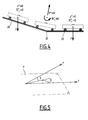
- step 5 This value is taken into account in step 5 for determining the wheel diameter. This makes it possible to increase the precision of the calculation in the portions of lane where a slope break occurs, that is to say a variation in the gradient of the slope, as illustrated in FIG. figure 4 .
- a track profile comprising a first descending section 26, a second flat section 28, a rupture of slope 30 occurring between the sections 26 and 28.
- the inertial sensor 24 when it acquires the acceleration value x "in the first direction, measures a total acceleration value which takes into account the contribution of the gravitation.As long as the slope is constant, the contribution of the gravitation to the acceleration is constant too, and the derivative x "'is not affected by the fact that the vehicle is on a sloping track section. This is true also for the horizontal portion 28.
- there is a break in slope and the contribution of gravitation to the acceleration along the first direction changes. This results in the fact that the contribution of gravitation to the value x "'becomes non-zero.
- Such a break in slope can be detected by the accelerometer 24 because at the point 30 ⁇ y 'varies.
- the calculator can then take into account for the estimation of the second magnitude not only x "', but also ⁇ y', more precisely, it corrects the value x" 'as a function of ⁇ y'. For example, it adds to x "'the contribution of gravitation, which is worth ⁇ y' g cos ⁇ y, where g is the acceleration of gravity.
- the computer does not perform step 5 when it detects that the variation of ⁇ y 'is greater than a predetermined value.
- the inertial sensor 24 acquires not only the acceleration of the vehicle in the first direction x ", but also the angular velocity of the vehicle around the first direction x, the second direction y and around the third direction. direction z, these angular velocities being noted respectively ⁇ x ', ⁇ y' and ⁇ z '.
- the computer does not perform step 5 when it detects that the variations of ⁇ x 'or ⁇ z' are greater than a predetermined value.
- one or both of the two angular offsets may not be zero.
- the acceleration x "measured in the first direction by the inertial sensor 24 is not strictly equal to the acceleration of the vehicle in the direction F.
- the values of y "and z", in addition to x ", are measured periodically with the aid of the inertial sensor 24. These values are used to estimate the angular offsets ⁇ and ⁇ .
Landscapes
- Engineering & Computer Science (AREA)
- Mechanical Engineering (AREA)
- Physics & Mathematics (AREA)
- General Physics & Mathematics (AREA)
- Length Measuring Devices With Unspecified Measuring Means (AREA)
- Regulating Braking Force (AREA)
Priority Applications (1)
| Application Number | Priority Date | Filing Date | Title |
|---|---|---|---|
| PL13168736T PL2666697T3 (pl) | 2012-05-25 | 2013-05-22 | Sposób oceny średnicy koła i powiązany zespół oceny |
Applications Claiming Priority (1)
| Application Number | Priority Date | Filing Date | Title |
|---|---|---|---|
| FR1254848A FR2991042B1 (fr) | 2012-05-25 | 2012-05-25 | Procede d'evaluation du diametre d'une roue, et ensemble d'evaluation associe |
Publications (2)
| Publication Number | Publication Date |
|---|---|
| EP2666697A1 true EP2666697A1 (de) | 2013-11-27 |
| EP2666697B1 EP2666697B1 (de) | 2019-08-21 |
Family
ID=48428404
Family Applications (1)
| Application Number | Title | Priority Date | Filing Date |
|---|---|---|---|
| EP13168736.0A Active EP2666697B1 (de) | 2012-05-25 | 2013-05-22 | Verfahren zur Bestimmung des Durchmessers eines Rads, und entsprechendes Bestimmungsmittel |
Country Status (7)
| Country | Link |
|---|---|
| EP (1) | EP2666697B1 (de) |
| AU (1) | AU2013206015B2 (de) |
| DK (1) | DK2666697T3 (de) |
| ES (1) | ES2754057T3 (de) |
| FR (1) | FR2991042B1 (de) |
| PL (1) | PL2666697T3 (de) |
| RU (1) | RU2629485C2 (de) |
Cited By (2)
| Publication number | Priority date | Publication date | Assignee | Title |
|---|---|---|---|---|
| EP3552920A1 (de) * | 2018-04-11 | 2019-10-16 | Siemens Mobility GmbH | Detektieren und unterdrücken von gleit- und schleuderzuständen von schienenfahrzeugen |
| EP3835716B1 (de) * | 2019-12-13 | 2025-11-05 | ALSTOM Holdings | Verfahren zur kontrolle der radverformung, entsprechende vorrichung und entsprechendes system, das diese vorrichtung umfasst |
Citations (6)
| Publication number | Priority date | Publication date | Assignee | Title |
|---|---|---|---|---|
| US4075538A (en) * | 1976-05-19 | 1978-02-21 | General Electric Company | Adaptive acceleration responsive system |
| JPH02293667A (ja) * | 1989-05-08 | 1990-12-04 | Hitachi Ltd | 列車速度検出方式 |
| EP0495693A1 (de) * | 1991-01-16 | 1992-07-22 | Faiveley Transport | Geschwindigkeitsauswertungsverfahren, insbesondere für die Winkelgeschwindigkeit eines Kraftfahrzeugrades, und Radschlupf-Steuerungsvorrichtung |
| EP1197419A1 (de) * | 2000-10-12 | 2002-04-17 | Siemens SGP Verkehrstechnik GmbH | Verfahren und Vorrichtung zur Bestimmung des Raddurchmessers und/oder der Fahrtgeschwindigkeit eines Schienenfährzeuges |
| US20040181320A1 (en) * | 2002-05-31 | 2004-09-16 | Kane Mark Edward | Method and system for compensating for wheel wear on a train |
| US20110231039A1 (en) * | 2008-11-19 | 2011-09-22 | Eureka Navigation Solutions Ag | Device and method for a rail vehicle |
Family Cites Families (1)
| Publication number | Priority date | Publication date | Assignee | Title |
|---|---|---|---|---|
| RU2203819C2 (ru) * | 2000-08-04 | 2003-05-10 | Открытое акционерное общество "Всероссийский научно-исследовательский институт транспортного машиностроения" | Способ и устройство измерения параметров износа колес рельсового транспортного средства |
-
2012
- 2012-05-25 FR FR1254848A patent/FR2991042B1/fr not_active Expired - Fee Related
-
2013
- 2013-05-22 DK DK13168736T patent/DK2666697T3/da active
- 2013-05-22 EP EP13168736.0A patent/EP2666697B1/de active Active
- 2013-05-22 ES ES13168736T patent/ES2754057T3/es active Active
- 2013-05-22 PL PL13168736T patent/PL2666697T3/pl unknown
- 2013-05-24 AU AU2013206015A patent/AU2013206015B2/en active Active
- 2013-05-24 RU RU2013123955A patent/RU2629485C2/ru active
Patent Citations (6)
| Publication number | Priority date | Publication date | Assignee | Title |
|---|---|---|---|---|
| US4075538A (en) * | 1976-05-19 | 1978-02-21 | General Electric Company | Adaptive acceleration responsive system |
| JPH02293667A (ja) * | 1989-05-08 | 1990-12-04 | Hitachi Ltd | 列車速度検出方式 |
| EP0495693A1 (de) * | 1991-01-16 | 1992-07-22 | Faiveley Transport | Geschwindigkeitsauswertungsverfahren, insbesondere für die Winkelgeschwindigkeit eines Kraftfahrzeugrades, und Radschlupf-Steuerungsvorrichtung |
| EP1197419A1 (de) * | 2000-10-12 | 2002-04-17 | Siemens SGP Verkehrstechnik GmbH | Verfahren und Vorrichtung zur Bestimmung des Raddurchmessers und/oder der Fahrtgeschwindigkeit eines Schienenfährzeuges |
| US20040181320A1 (en) * | 2002-05-31 | 2004-09-16 | Kane Mark Edward | Method and system for compensating for wheel wear on a train |
| US20110231039A1 (en) * | 2008-11-19 | 2011-09-22 | Eureka Navigation Solutions Ag | Device and method for a rail vehicle |
Cited By (2)
| Publication number | Priority date | Publication date | Assignee | Title |
|---|---|---|---|---|
| EP3552920A1 (de) * | 2018-04-11 | 2019-10-16 | Siemens Mobility GmbH | Detektieren und unterdrücken von gleit- und schleuderzuständen von schienenfahrzeugen |
| EP3835716B1 (de) * | 2019-12-13 | 2025-11-05 | ALSTOM Holdings | Verfahren zur kontrolle der radverformung, entsprechende vorrichung und entsprechendes system, das diese vorrichtung umfasst |
Also Published As
| Publication number | Publication date |
|---|---|
| ES2754057T3 (es) | 2020-04-15 |
| FR2991042B1 (fr) | 2014-06-27 |
| RU2629485C2 (ru) | 2017-08-29 |
| AU2013206015A1 (en) | 2013-12-12 |
| DK2666697T3 (da) | 2019-11-04 |
| FR2991042A1 (fr) | 2013-11-29 |
| EP2666697B1 (de) | 2019-08-21 |
| AU2013206015B2 (en) | 2016-07-07 |
| RU2013123955A (ru) | 2014-11-27 |
| PL2666697T3 (pl) | 2020-02-28 |
Similar Documents
| Publication | Publication Date | Title |
|---|---|---|
| EP2219930B1 (de) | Vorrichtung zum messen der bewegung eines selbstgesteuerten fahrzeugs | |
| EP2219931B1 (de) | Vorrichtung zum messen der bewegung eines selbstgesteuerten fahrzeugs | |
| EP2749471B1 (de) | Verfahren zur geschwindigkeitsbestimmung eines schienenfahrzeugs | |
| CA2364116C (fr) | Procede et dispositif de localisation d'un vehicule sur une voie | |
| FR2543901A1 (fr) | Dispositif pour detecter une partie plate d'une surface peripherique de roues de vehicule | |
| EP2507101B1 (de) | Verfahren zur bestimmung des gefälles einer strasse | |
| FR2990178A1 (fr) | Procede pour securiser le deplacement d'un vehicule ferroviaire, et vehicule ferroviaire | |
| EP2666697B1 (de) | Verfahren zur Bestimmung des Durchmessers eines Rads, und entsprechendes Bestimmungsmittel | |
| EP1324889B1 (de) | Verfahren zur automatischen ortung von den links- und rechtsrädern eines kraftfahrzeuges | |
| EP3006897B1 (de) | Navigationsverfahren eines fahrzeugs, navigationsvorrichtung und fahrzeug für die umsetzung dieses verfahrens | |
| EP3959523B1 (de) | Verfahren zur schätzung und anpassung der geschwindigkeit und beschleunigung eines fahrzeugs | |
| EP1007976B1 (de) | Verfahren zum messen der giergeschwindigkeit eines fahrzeuges | |
| EP4121782B1 (de) | Verfahren zur schätzung einer längsbeschleunigung mindestens eines schienenfahrzeugs | |
| EP1597133B1 (de) | Verfahren und system zum abschätzen der winkelposition eines lenkrads an einem kraftfahrzeug | |
| FR2920047A3 (fr) | Estimation de la pente de la route depuis un vehicule | |
| FR2935807A1 (fr) | Procede de detection de l'arret d'un vehicule automobile | |
| EP2660122B1 (de) | Verfahren und System zum Sichern der Bewegung eines Schienenfahrzeugs, Steuereinheit für das Schienenfahrzeug, und ein solches Schienenfahrzeug | |
| FR3051056B1 (fr) | Dispositif et procede de determination de position d’un vehicule, et dispositif d’aide a la conduite comprenant un tel dispositif de determination de position | |
| JPH07229754A (ja) | 電気車の走行距離演算装置 | |
| EP0919814A1 (de) | Verfahren zur Abschätzung der Geschwindigkeit eines Fahrzeuges oder mehrerer miteinander verbundener Fahrzeuge | |
| FR2779518A1 (fr) | Procede optique de reconstruction du trace d'une voie le long de laquelle se deplace un vehicule guide | |
| JP7530516B2 (ja) | 速度検出装置および速度検出方法 | |
| CA2491648A1 (fr) | Procede et dispositif pour mesurer le poids applique au sol par au moins un essieu | |
| NL2037854A (nl) | Werkwijze voor het bepalen van een snelheidswaarde van een enkelsporig voertuig | |
| FR2861468A1 (fr) | Procede et dispositif de mesure de la vitesse d'un vehicule en deplacement sur une trajectoire determinee |
Legal Events
| Date | Code | Title | Description |
|---|---|---|---|
| PUAI | Public reference made under article 153(3) epc to a published international application that has entered the european phase |
Free format text: ORIGINAL CODE: 0009012 |
|
| AK | Designated contracting states |
Kind code of ref document: A1 Designated state(s): AL AT BE BG CH CY CZ DE DK EE ES FI FR GB GR HR HU IE IS IT LI LT LU LV MC MK MT NL NO PL PT RO RS SE SI SK SM TR |
|
| AX | Request for extension of the european patent |
Extension state: BA ME |
|
| 17P | Request for examination filed |
Effective date: 20140527 |
|
| RBV | Designated contracting states (corrected) |
Designated state(s): AL AT BE BG CH CY CZ DE DK EE ES FI FR GB GR HR HU IE IS IT LI LT LU LV MC MK MT NL NO PL PT RO RS SE SI SK SM TR |
|
| RAP1 | Party data changed (applicant data changed or rights of an application transferred) |
Owner name: ALSTOM TRANSPORT TECHNOLOGIES |
|
| GRAP | Despatch of communication of intention to grant a patent |
Free format text: ORIGINAL CODE: EPIDOSNIGR1 |
|
| STAA | Information on the status of an ep patent application or granted ep patent |
Free format text: STATUS: GRANT OF PATENT IS INTENDED |
|
| INTG | Intention to grant announced |
Effective date: 20190314 |
|
| GRAS | Grant fee paid |
Free format text: ORIGINAL CODE: EPIDOSNIGR3 |
|
| GRAA | (expected) grant |
Free format text: ORIGINAL CODE: 0009210 |
|
| STAA | Information on the status of an ep patent application or granted ep patent |
Free format text: STATUS: THE PATENT HAS BEEN GRANTED |
|
| AK | Designated contracting states |
Kind code of ref document: B1 Designated state(s): AL AT BE BG CH CY CZ DE DK EE ES FI FR GB GR HR HU IE IS IT LI LT LU LV MC MK MT NL NO PL PT RO RS SE SI SK SM TR |
|
| REG | Reference to a national code |
Ref country code: GB Ref legal event code: FG4D Free format text: NOT ENGLISH |
|
| REG | Reference to a national code |
Ref country code: CH Ref legal event code: EP |
|
| REG | Reference to a national code |
Ref country code: DE Ref legal event code: R082 Ref document number: 602013059376 Country of ref document: DE Representative=s name: LAVOIX MUNICH, DE |
|
| REG | Reference to a national code |
Ref country code: DE Ref legal event code: R096 Ref document number: 602013059376 Country of ref document: DE |
|
| REG | Reference to a national code |
Ref country code: AT Ref legal event code: REF Ref document number: 1169409 Country of ref document: AT Kind code of ref document: T Effective date: 20190915 |
|
| REG | Reference to a national code |
Ref country code: IE Ref legal event code: FG4D Free format text: LANGUAGE OF EP DOCUMENT: FRENCH |
|
| REG | Reference to a national code |
Ref country code: CH Ref legal event code: NV Representative=s name: MICHELI AND CIE SA, CH |
|
| REG | Reference to a national code |
Ref country code: DK Ref legal event code: T3 Effective date: 20191031 |
|
| REG | Reference to a national code |
Ref country code: NL Ref legal event code: FP |
|
| REG | Reference to a national code |
Ref country code: SE Ref legal event code: TRGR |
|
| REG | Reference to a national code |
Ref country code: LT Ref legal event code: MG4D |
|
| PG25 | Lapsed in a contracting state [announced via postgrant information from national office to epo] |
Ref country code: FI Free format text: LAPSE BECAUSE OF FAILURE TO SUBMIT A TRANSLATION OF THE DESCRIPTION OR TO PAY THE FEE WITHIN THE PRESCRIBED TIME-LIMIT Effective date: 20190821 Ref country code: LT Free format text: LAPSE BECAUSE OF FAILURE TO SUBMIT A TRANSLATION OF THE DESCRIPTION OR TO PAY THE FEE WITHIN THE PRESCRIBED TIME-LIMIT Effective date: 20190821 Ref country code: NO Free format text: LAPSE BECAUSE OF FAILURE TO SUBMIT A TRANSLATION OF THE DESCRIPTION OR TO PAY THE FEE WITHIN THE PRESCRIBED TIME-LIMIT Effective date: 20191121 Ref country code: BG Free format text: LAPSE BECAUSE OF FAILURE TO SUBMIT A TRANSLATION OF THE DESCRIPTION OR TO PAY THE FEE WITHIN THE PRESCRIBED TIME-LIMIT Effective date: 20191121 Ref country code: PT Free format text: LAPSE BECAUSE OF FAILURE TO SUBMIT A TRANSLATION OF THE DESCRIPTION OR TO PAY THE FEE WITHIN THE PRESCRIBED TIME-LIMIT Effective date: 20191223 Ref country code: HR Free format text: LAPSE BECAUSE OF FAILURE TO SUBMIT A TRANSLATION OF THE DESCRIPTION OR TO PAY THE FEE WITHIN THE PRESCRIBED TIME-LIMIT Effective date: 20190821 |
|
| PG25 | Lapsed in a contracting state [announced via postgrant information from national office to epo] |
Ref country code: IS Free format text: LAPSE BECAUSE OF FAILURE TO SUBMIT A TRANSLATION OF THE DESCRIPTION OR TO PAY THE FEE WITHIN THE PRESCRIBED TIME-LIMIT Effective date: 20191221 Ref country code: LV Free format text: LAPSE BECAUSE OF FAILURE TO SUBMIT A TRANSLATION OF THE DESCRIPTION OR TO PAY THE FEE WITHIN THE PRESCRIBED TIME-LIMIT Effective date: 20190821 Ref country code: GR Free format text: LAPSE BECAUSE OF FAILURE TO SUBMIT A TRANSLATION OF THE DESCRIPTION OR TO PAY THE FEE WITHIN THE PRESCRIBED TIME-LIMIT Effective date: 20191122 Ref country code: RS Free format text: LAPSE BECAUSE OF FAILURE TO SUBMIT A TRANSLATION OF THE DESCRIPTION OR TO PAY THE FEE WITHIN THE PRESCRIBED TIME-LIMIT Effective date: 20190821 Ref country code: AL Free format text: LAPSE BECAUSE OF FAILURE TO SUBMIT A TRANSLATION OF THE DESCRIPTION OR TO PAY THE FEE WITHIN THE PRESCRIBED TIME-LIMIT Effective date: 20190821 |
|
| PG25 | Lapsed in a contracting state [announced via postgrant information from national office to epo] |
Ref country code: TR Free format text: LAPSE BECAUSE OF FAILURE TO SUBMIT A TRANSLATION OF THE DESCRIPTION OR TO PAY THE FEE WITHIN THE PRESCRIBED TIME-LIMIT Effective date: 20190821 |
|
| REG | Reference to a national code |
Ref country code: ES Ref legal event code: FG2A Ref document number: 2754057 Country of ref document: ES Kind code of ref document: T3 Effective date: 20200415 |
|
| PG25 | Lapsed in a contracting state [announced via postgrant information from national office to epo] |
Ref country code: EE Free format text: LAPSE BECAUSE OF FAILURE TO SUBMIT A TRANSLATION OF THE DESCRIPTION OR TO PAY THE FEE WITHIN THE PRESCRIBED TIME-LIMIT Effective date: 20190821 Ref country code: RO Free format text: LAPSE BECAUSE OF FAILURE TO SUBMIT A TRANSLATION OF THE DESCRIPTION OR TO PAY THE FEE WITHIN THE PRESCRIBED TIME-LIMIT Effective date: 20190821 |
|
| PG25 | Lapsed in a contracting state [announced via postgrant information from national office to epo] |
Ref country code: SM Free format text: LAPSE BECAUSE OF FAILURE TO SUBMIT A TRANSLATION OF THE DESCRIPTION OR TO PAY THE FEE WITHIN THE PRESCRIBED TIME-LIMIT Effective date: 20190821 Ref country code: IS Free format text: LAPSE BECAUSE OF FAILURE TO SUBMIT A TRANSLATION OF THE DESCRIPTION OR TO PAY THE FEE WITHIN THE PRESCRIBED TIME-LIMIT Effective date: 20200224 Ref country code: CZ Free format text: LAPSE BECAUSE OF FAILURE TO SUBMIT A TRANSLATION OF THE DESCRIPTION OR TO PAY THE FEE WITHIN THE PRESCRIBED TIME-LIMIT Effective date: 20190821 Ref country code: SK Free format text: LAPSE BECAUSE OF FAILURE TO SUBMIT A TRANSLATION OF THE DESCRIPTION OR TO PAY THE FEE WITHIN THE PRESCRIBED TIME-LIMIT Effective date: 20190821 |
|
| REG | Reference to a national code |
Ref country code: DE Ref legal event code: R097 Ref document number: 602013059376 Country of ref document: DE |
|
| PLBE | No opposition filed within time limit |
Free format text: ORIGINAL CODE: 0009261 |
|
| STAA | Information on the status of an ep patent application or granted ep patent |
Free format text: STATUS: NO OPPOSITION FILED WITHIN TIME LIMIT |
|
| PG2D | Information on lapse in contracting state deleted |
Ref country code: IS |
|
| 26N | No opposition filed |
Effective date: 20200603 |
|
| PG25 | Lapsed in a contracting state [announced via postgrant information from national office to epo] |
Ref country code: SI Free format text: LAPSE BECAUSE OF FAILURE TO SUBMIT A TRANSLATION OF THE DESCRIPTION OR TO PAY THE FEE WITHIN THE PRESCRIBED TIME-LIMIT Effective date: 20190821 |
|
| PG25 | Lapsed in a contracting state [announced via postgrant information from national office to epo] |
Ref country code: MC Free format text: LAPSE BECAUSE OF FAILURE TO SUBMIT A TRANSLATION OF THE DESCRIPTION OR TO PAY THE FEE WITHIN THE PRESCRIBED TIME-LIMIT Effective date: 20190821 |
|
| REG | Reference to a national code |
Ref country code: AT Ref legal event code: UEP Ref document number: 1169409 Country of ref document: AT Kind code of ref document: T Effective date: 20190821 |
|
| PG25 | Lapsed in a contracting state [announced via postgrant information from national office to epo] |
Ref country code: LU Free format text: LAPSE BECAUSE OF NON-PAYMENT OF DUE FEES Effective date: 20200522 |
|
| PG25 | Lapsed in a contracting state [announced via postgrant information from national office to epo] |
Ref country code: IE Free format text: LAPSE BECAUSE OF NON-PAYMENT OF DUE FEES Effective date: 20200522 |
|
| PG25 | Lapsed in a contracting state [announced via postgrant information from national office to epo] |
Ref country code: MT Free format text: LAPSE BECAUSE OF FAILURE TO SUBMIT A TRANSLATION OF THE DESCRIPTION OR TO PAY THE FEE WITHIN THE PRESCRIBED TIME-LIMIT Effective date: 20190821 Ref country code: CY Free format text: LAPSE BECAUSE OF FAILURE TO SUBMIT A TRANSLATION OF THE DESCRIPTION OR TO PAY THE FEE WITHIN THE PRESCRIBED TIME-LIMIT Effective date: 20190821 |
|
| PG25 | Lapsed in a contracting state [announced via postgrant information from national office to epo] |
Ref country code: MK Free format text: LAPSE BECAUSE OF FAILURE TO SUBMIT A TRANSLATION OF THE DESCRIPTION OR TO PAY THE FEE WITHIN THE PRESCRIBED TIME-LIMIT Effective date: 20190821 |
|
| P01 | Opt-out of the competence of the unified patent court (upc) registered |
Effective date: 20230823 |
|
| REG | Reference to a national code |
Ref country code: GB Ref legal event code: 732E Free format text: REGISTERED BETWEEN 20250213 AND 20250219 |
|
| REG | Reference to a national code |
Ref country code: ES Ref legal event code: PC2A Owner name: ALSTOM HOLDINGS Effective date: 20250310 |
|
| REG | Reference to a national code |
Ref country code: BE Ref legal event code: PD Owner name: ALSTOM HOLDINGS; FR Free format text: DETAILS ASSIGNMENT: CHANGE OF OWNER(S), ASSIGNMENT; FORMER OWNER NAME: ALSTOM TRANSPORT TECHNOLOGIES Effective date: 20241025 |
|
| PGFP | Annual fee paid to national office [announced via postgrant information from national office to epo] |
Ref country code: NL Payment date: 20250521 Year of fee payment: 13 |
|
| PGFP | Annual fee paid to national office [announced via postgrant information from national office to epo] |
Ref country code: PL Payment date: 20250508 Year of fee payment: 13 Ref country code: DE Payment date: 20250521 Year of fee payment: 13 |
|
| PGFP | Annual fee paid to national office [announced via postgrant information from national office to epo] |
Ref country code: DK Payment date: 20250526 Year of fee payment: 13 Ref country code: ES Payment date: 20250627 Year of fee payment: 13 |
|
| PGFP | Annual fee paid to national office [announced via postgrant information from national office to epo] |
Ref country code: IT Payment date: 20250527 Year of fee payment: 13 Ref country code: BE Payment date: 20250521 Year of fee payment: 13 |
|
| PGFP | Annual fee paid to national office [announced via postgrant information from national office to epo] |
Ref country code: FR Payment date: 20250528 Year of fee payment: 13 |
|
| PGFP | Annual fee paid to national office [announced via postgrant information from national office to epo] |
Ref country code: CH Payment date: 20250601 Year of fee payment: 13 |
|
| PGFP | Annual fee paid to national office [announced via postgrant information from national office to epo] |
Ref country code: AT Payment date: 20250522 Year of fee payment: 13 |
|
| PGFP | Annual fee paid to national office [announced via postgrant information from national office to epo] |
Ref country code: SE Payment date: 20250521 Year of fee payment: 13 |
|
| PGFP | Annual fee paid to national office [announced via postgrant information from national office to epo] |
Ref country code: GB Payment date: 20260306 Year of fee payment: 14 |