EP2666700A1 - Dispositif de conduite - Google Patents
Dispositif de conduite Download PDFInfo
- Publication number
- EP2666700A1 EP2666700A1 EP11794390.2A EP11794390A EP2666700A1 EP 2666700 A1 EP2666700 A1 EP 2666700A1 EP 11794390 A EP11794390 A EP 11794390A EP 2666700 A1 EP2666700 A1 EP 2666700A1
- Authority
- EP
- European Patent Office
- Prior art keywords
- shaft
- impact
- female
- male
- serration
- Prior art date
- Legal status (The legal status is an assumption and is not a legal conclusion. Google has not performed a legal analysis and makes no representation as to the accuracy of the status listed.)
- Granted
Links
Images


Classifications
-
- B—PERFORMING OPERATIONS; TRANSPORTING
- B62—LAND VEHICLES FOR TRAVELLING OTHERWISE THAN ON RAILS
- B62D—MOTOR VEHICLES; TRAILERS
- B62D1/00—Steering controls, i.e. means for initiating a change of direction of the vehicle
- B62D1/02—Steering controls, i.e. means for initiating a change of direction of the vehicle vehicle-mounted
- B62D1/16—Steering columns
- B62D1/18—Steering columns yieldable or adjustable, e.g. tiltable
- B62D1/19—Steering columns yieldable or adjustable, e.g. tiltable incorporating energy-absorbing arrangements, e.g. by being yieldable or collapsible
- B62D1/192—Yieldable or collapsible columns
-
- F—MECHANICAL ENGINEERING; LIGHTING; HEATING; WEAPONS; BLASTING
- F16—ENGINEERING ELEMENTS AND UNITS; GENERAL MEASURES FOR PRODUCING AND MAINTAINING EFFECTIVE FUNCTIONING OF MACHINES OR INSTALLATIONS; THERMAL INSULATION IN GENERAL
- F16F—SPRINGS; SHOCK-ABSORBERS; MEANS FOR DAMPING VIBRATION
- F16F7/00—Vibration-dampers; Shock-absorbers
- F16F7/12—Vibration-dampers; Shock-absorbers using plastic deformation of members
- F16F7/125—Units with a telescopic-like action as one member moves into, or out of a second member
Definitions
- the invention relates to a steering device, and in particular, to a steering device capable of transferring a rotation torque, and mitigating an impact applied to a driver by undergoing relative contraction in the axial direction thereof at the time of a collision, such as, for example, a steering device having an intermediate shaft, a steering shaft, and so forth.
- the steering device is provided with a steering shaft 12 in which a steering wheel can be mounted, the steering shaft 12 being on the rear side of a vehicle body (on the right-hand side in the Fig. 7 ), a steering column 13 with the steering shaft 12 inserted therethrough, and a steering gear coupled to the steering column 13 via a rack and pinion mechanism (not shown), the steering gear being on the front side of the vehicle body (on the left-hand side in the Fig. 7 ).
- a female steering shaft (female shaft) 12A is serration (or spline) -fitted onto a male steering shaft (male shaft) 12B in such a way as to cause a rotation torque to be transferable, and these members to be relatively movable in the axial direction of the steering shaft 12. Accordingly, the female steering shaft 12A and the male steering shaft 12B causes a spline-fitted joint to make a relative movement at the time of a collision, thereby enabling the whole length of the steering shaft 12 to be contracted.
- the steering column 13 cylindrical in shape, with the steering shaft 12 inserted therethrough, has a so-called collapsible structure. More specifically, an outer column 13A and an inner column 13B are combined with each other in such a way as to be telescopically movable, and if an impact in the axial direction is applied thereto at the time of a collision, the steering column 13 undergoes contraction in total length while absorbing energy of the impact.
- the outer column 12A is supported by a part of a body 18, such as the underside of a dashboard, and so forth, through the intermediary of an upper support bracket 14. Further, a stopper (not shown) is provided between the upper support bracket 14, and the body 18 such that the upper support bracket 14 is dislodged from the stopper to be movable toward the front side of the body when an impact in a direction toward the front side of the body is applied to the upper support bracket 14. Further, an end of the inner column 13B, on a side thereof, adjacent to the front of the body, is also supported by a part of the body 18 through the intermediary of a lower support bracket 19.
- the rotation of a steering wheel 11 is transferred to the steering gear via the male steering shaft 123, the female steering shaft 12A, the universal coupling 15, the female intermediate shaft 16A, the male intermediate shaft 16B, and the universal coupling 17, thereby causing wheels (not shown) of a vehicle to be steered.
- the steering device described as above need to have a structure constructed such that at a time when the male shaft is serration (or spline) -fitted into the female male shaft upon occurrence of a vehicle collision to undergo relative contraction, resistance to collapsing in the middle of the contraction is increased to thereby increase an absorption amount of impact energy, enabling the impact energy to be sufficiently absorbed even at a short collapse-stroke.
- Patent Document 1 there is disclosed such an impact-absorption type steering shaft as shown in Fig. 8 .
- Fig. 8(a) is a sectional view showing principal parts of the male shaft 12B, and the female shaft 12A, shown in Fig. 7 , respectively, and Fig. 8(b) is an enlarged perspective view of a part R shown in 8 (a).
- a male serration 20 formed on the outer periphery of the left-end of the male shaft 12B is fitted into a female serration 30 formed on the inner periphery of the right-end of the female shaft 12A to be brought into serration-engagement with the latter.
- a protrusion 23 is formed in a recess 22 between tooth 21 of the male serration 20, positioned at a part of the male serration 20, in the axial direction thereof, located at a spot in the circumferential direction thereof.
- the position of the protrusion 23, in the axial direction of the male serration 20, is a position where the protrusion 23 will not come into engagement with the female serration 30 at the time of a normal driving operation, allowing the protrusion 23 to come into engagement with the female serration 30 when the male shaft and the female male shaft undergo relative contraction at the time of a vehicle collision.
- the protrusion 23 of the male serration 20 is brought into engagement with a serrated edge of the female serration 30 to thereby cause the serrated edge of the female serration 30 to undergo plastic deformation.
- the resistance to collapsing will increase, thereby causing an absorption amount of impact energy to be increased.
- Patent Document 2 there is available an impact-absorption type steering shaft having a configuration such that a female steering shaft 12A, and a male steering shaft 12B undergo plastic deformation into the shape of an ellipse in cross-section by pressing down the outer peripheral surface of the female steering shaft 12A inward in the radial direction thereof to thereby absorb impact energy.
- a structure of Patent Document 2 is applied to the structure of Patent Document 1, this will render it difficult to align the position of the protrusion 23, in the circumferential direction of the male serration 20, with the phase of the ellipse formed due to the plastic deformation, so that it has been difficult to set the absorption amount of impact energy to a predetermined magnitude.
- a steering device comprising a male shaft capable of transferring rotation of a steering wheel, a male serration formed on the outer periphery of the male shaft, a female shaft fitted onto the male shaft, and a female serration formed on the inner periphery of the female shaft to be brought into engagement with the male serration in such a way as to be relatively movable in the axial direction of the male serration, and to cause a rotation torque to be transferable, wherein an impact-energy absorption part formed in such a way as to surround the whole circumference of the outer periphery of the male shaft, having a predetermined length in the axial direction of the male serration, an outside diameter of the impact-energy absorption part being larger in size than a diameter of a circle of a serrated edge of the female serration, so as to cause the serrated edge of the female serration to be butted against the impact-energy absorption
- the invention provides in its second aspect the steering device wherein the impact-energy absorption part is formed at a plurality of spots apart from each other in the axial direction of the male shaft.
- the invention provides in its third aspect the steering device wherein a length of the impact-energy absorption part, in the axial direction thereof, is set such that an absorption amount of the impact energy will be at a predetermined magnitude.
- the invention provides in its fourth aspect the steering device wherein an outside diameter size of the impact-energy absorption part is set such that an absorption amount of the impact energy will be at a predetermined magnitude.
- the invention provides in its fifth aspect the steering device wherein hardness of the male shaft is set such that an absorption amount of the impact energy will be at a predetermined magnitude.
- the invention provides in its sixth aspect the steering device wherein a tilt angle of a butting surface where the impact-energy absorption part is butted against the serrated edge of the female serration is set such that an absorption amount of the impact energy will be at a predetermined magnitude.
- the invention provides in its seventh aspect the steering device wherein a tilt angle of a butting surface where the serrated edge of the female serration is butted against the impact-energy absorption part is set such that an absorption amount of the impact energy will be at a predetermined magnitude.
- the invention provides in its eighth aspect the steering device wherein an outer peripheral surface of the female shaft is pressed inward in the radial direction thereof to thereby cause the female shaft, and the male shaft to undergo plastic deformation into the shape of an ellipse in cross-section such that an absorption amount of the impact energy will be at a predetermined magnitude.
- the serrated edge of the female serration is butted against the impact-energy absorption part , throughout the outer periphery of the male shaft, in the circumferential direction thereof, so that the absorption amount of impact energy can be stabilized, rendering it easier to set the absorption amount of impact energy to a predetermined magnitude.
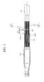
- Fig. 1 is a sectional view showing principal parts of a male shaft, and a female shaft, respectively, as to a steering device according to the first embodiment of the invention.
- Fig. 2 is a cross-sectional view taken on line A-A of Fig. 1
- Fig. 3(a) is an enlarged sectional view of a part P shown in Fig. 1 .
- a male serration 20 formed on the outer periphery of the left-end of a male shaft 12B is fitted into a female serration 30 formed on the inner periphery of the right-end of a female shaft 12A to be brought into serration-engagement with the latter.
- the male shaft 12B is formed in the shape of a hollow cylinder (not shown).
- the male serration 20 includes an impact-energy absorption part 40 formed at a position away from a right-end surface (a butting surface) 121A of the female shaft 12A by a length L1.
- the impact-energy absorption part 40 has a length L2 in the axial direction of the male serration 20, and is formed in the shape of a cylinder surrounding the whole circumference of the outer periphery of the male shaft 12B.
- the impact-energy absorption part 40 is formed such that the outside diameter size D1 thereof is larger in size than a diameter D2 of a serrated edge circle of a serrated edge 31 of the female serration 30.
- an outer peripheral surface 122A of the right-end of the female shaft 12A shown in Fig. 1 is pressed inward from the outer peripheral side thereof to be slightly crushed, thereby causing the female shaft 12A, and the male shaft 12B to undergo plastic deformation into the shape of an ellipse.
- the male shaft 12B is united with the female shaft 12A so as to prevent relative movement in the axial direction thereof unless a strong force to an extent, in the axial direction thereof, is applied thereto.
- the serrated edge 31 on the right-end surface (the butting surface) 121A of the female shaft 12A is butted against a left-end surface 41 (a butting surface) of the impact-energy absorption part 40. Then, the serrated edge 31 of the female serration 30 is firmly butted against the left-end surface 41 (the butting surface) of the impact-energy absorption part 40 to undergo plastic deformation, whereupon resistance to collapsing increases, thereby absorbing impact energy.
- the serrated edge 31 of the female serration 30 is butted against the left-end surface 41 of the impact-energy absorption part 40, surrounding the whole outer periphery of the male shaft 12B, in the circumferential direction thereof, so that torsion does not occur between the female shaft 12A, and the male shaft 12B, and an absorption amount of impact energy is stabilized.
- the outer peripheral surface 122A of the right-end of the female shaft 12A is crushed to undergo plastic deformation into the shape of the ellipse, it is possible to set the absorption amount of impact energy to a predetermined magnitude regardless of a phase of the ellipse formed due to the plastic deformation because the impact-energy absorption part 40 is formed in the shape of the cylinder surrounding the whole circumference of the outer periphery of the male shaft 12B.
- At least one factor selected from among the length L2 of the impact-energy absorption part 40, in the axial direction thereof, the outside diameter size D1 of the impact-energy absorption part 40, and hardness of the male shaft 12B is set to a predetermined magnitude, this will enable the absorption amount of impact energy to be set to a predetermined magnitude.
- at least one factor selected from among a tilt angle ⁇ 1 of the serrated edge 31 of the right-end surface (the butting surface) 121A of the female shaft 12A, and a tilt angle ⁇ 2 of the left-end surface 41 (the butting surface) of the impact-energy absorption part 40, as shown in Fig. 3 (b) is set to a predetermined magnitude, this will enable the absorption amount of impact energy to be set to a predetermined magnitude.
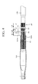
- Fig. 4 is a sectional view showing principal parts of a male shaft, and a female shaft, respectively, as to the steering device according to the second embodiment of the invention
- Fig. 5 is an enlarged sectional view of a part Q shown in Fig. 4 .
- the second embodiment of the invention is a variation of the first embodiment, representing an example in which an impact-energy absorption part is formed at a plurality of spots apart from each other, in the axial direction of a male shaft 12B.
- a male serration 20 is provided with an impact-energy absorption part 40 that is formed at a position away from a right-end surface (a butting surface) 121A of a female shaft 12A by a length L1.
- an impact-energy absorption part 50 is formed at a position away from the impact-energy absorption part 40 by a length L3.
- the impact-energy absorption part 40 having a length L2, in the axial direction of the male serration 20, and the impact-energy absorption part 50 having a length L4, in the axial direction of the male serration 20, are each formed in the shape of a cylinder so as to surround the whole circumference of the outer periphery of the male shaft 12B.
- the impact-energy absorption part 40 having an outside diameter size D1, and the impact-energy absorption part 50 having an outside diameter size D3 are formed such that D1, D3 each are larger in size than a diameter D2 of a serrated edge circle of a serrated edge 31 of the female serration 30.
- an outer peripheral surface 122A of the right-end of the female shaft 12A shown in Fig. 4 is pressed inward from the outer peripheral side thereof to be slightly crushed, thereby causing the female shaft 12A, and the male shaft 12B to undergo plastic deformation into the shape of an ellipse.
- the male shaft 12B is united with the female shaft 12A so as to prevent relative movement in the axial direction thereof unless a strong force to an extent, in the axial direction thereof, is applied thereto.
- a serrated edge 31 on a right-end surface (a butting surface) 121A of the female shaft 12A is butted against a left-end surface 41 (a butting surface) of the impact-energy absorption part 40. Then, the serrated edge 31 of the female serration 30 is firmly butted against the left-end surface 41 (the butting surface) of the impact-energy absorption part 40 to undergo plastic deformation, whereupon resistance to collapsing increases, thereby absorbing impact energy.
- the serrated edge 31 on the right-end surface (the butting surface) 121A of the female shaft 12A is butted against a left-end surface 51 (a butting surface) of the impact-energy absorption part 50. Then, the serrated edge 31 of the female serration 30 is firmly butted against the left-end surface 51 (the butting surface) of the impact-energy absorption part 50 to undergo plastic deformation, whereupon resistance to collapsing increases, thereby absorbing impact energy.
- the impact-energy absorption parts 40, 50 are formed at two spots apart from each other, respectively, in the axial direction of the male shaft 12B. Accordingly, it is possible to set an absorption characteristic of impact energy to a predetermined magnitude in accordance with the position of a collapse-move stroke, in the steering device.
- Fig. 6 is a sectional view showing principal parts of a male shaft, and a female shaft, respectively, as to a steering device according to the third embodiment of the invention.
- a steering device according to the third embodiment of the invention there are described only parts differing in structure from those according to the first embodiment, thereby omitting duplicated description.
- components identical to those according to the first embodiment are denoted by like reference numerals, respectively.
- the third embodiment of the invention is a variation of the first embodiment, representing an example in which an impact-energy absorption part is formed at a female shaft as well as a male shaft of a steering device capable of adjusting a telescopic position of a steering wheel.
- an outer column 13A is fitted onto an inner column 13B in such a way as to enable a telescopic-position to be adjusted by a telescopic-position adjust length L1.
- a male shaft 12B is rotatably, and axially supported by the outer column 13A, and a female shaft 12A is rotatably, and axially supported by the inner column 13B, the steering wheel being fittable to the right end of the female shaft 12A.
- a male serration 20 formed on the outer periphery of the left-end of the male shaft 12B is fitted into a female serration 30 formed on the inner periphery of the right-end of the female shaft 12A to be brought into serration-engagement wi th the latter. If the telescopic-position of the outer column 13A, in relation to the inner column 13B, is adjusted to suit the physique of a driver, the male serration 20 of themale shaft 12B will smoothly expand, and contract against the female serration 30 of the female shaft 12A within a range of the telescopic-position adjust length L1.
- the male serration 20 includes an impact-energy absorption part 40 formed at a position away from a right-end surface (a butting surface) 121A of the female shaft 12A by a length L1 (identical to the telescopic-position adjust length L1).
- the impact-energy absorption part 40 has a length L2, in the axial direction of the male serration 20, being formed in the shape of a cylinder surrounding the whole circumference of the outer periphery of the male shaft 12B.
- the impact-energy absorption part 40 is formed such that an outside diameter size D1 thereof is larger in size than a diameter D2 of a serrated edge circle of a serrated edge 31 of the female serration 30.
- the serrated edge 31 on the right-end surface (the butting surface) 121A of the female shaft 12A is butted against a left-end surface 41 (a butting surface) of the impact-energy absorption part 40. Then, the serrated edge 31 is firmly butted against the left-end surface 41 (the butting surface) of the impact-energy absorption part 40 to undergo plastic deformation, whereupon resistance to collapsing increases, thereby absorbing impact energy.
- the serrated edge 31 of the female shaft 12A is butted against the left-end surface 41 of the impact-energy absorption part 40, surrounding the whole outer periphery of the male shaft 12B, in the circumferential direction thereof, so that torsion does not occur between the female shaft 12A, and the male shaft 12B, thereby stabilizing an absorption amount of impact energy.
- the serration is formed on the female shaft 12A, and the male shaft 12B, respectively, however, splines instead of the serration may be formed on the female shaft 12A, and the male shaft 12B, respectively.
- the invention has been applied to the steering shaft, however, the invention may be applied to an intermediate shaft instead.
- the impact-energy absorption part is formed at two spots apart from each other, in the axial direction of the male shaft 12B, however, the impact-energy absorption part may be formed at not less than two spots apart from each other, in the axial direction of the male shaft 12B.
Landscapes
- Engineering & Computer Science (AREA)
- Mechanical Engineering (AREA)
- General Engineering & Computer Science (AREA)
- Chemical & Material Sciences (AREA)
- Combustion & Propulsion (AREA)
- Transportation (AREA)
- Steering Controls (AREA)
- Vibration Dampers (AREA)
Applications Claiming Priority (3)
| Application Number | Priority Date | Filing Date | Title |
|---|---|---|---|
| JP2011010822 | 2011-01-21 | ||
| JP2011190127A JP5494593B2 (ja) | 2011-01-21 | 2011-08-31 | ステアリング装置 |
| PCT/JP2011/072928 WO2012098738A1 (fr) | 2011-01-21 | 2011-10-05 | Dispositif de conduite |
Publications (3)
| Publication Number | Publication Date |
|---|---|
| EP2666700A1 true EP2666700A1 (fr) | 2013-11-27 |
| EP2666700A4 EP2666700A4 (fr) | 2016-06-22 |
| EP2666700B1 EP2666700B1 (fr) | 2017-12-13 |
Family
ID=46515380
Family Applications (1)
| Application Number | Title | Priority Date | Filing Date |
|---|---|---|---|
| EP11794390.2A Not-in-force EP2666700B1 (fr) | 2011-01-21 | 2011-10-05 | Dispositif de conduite |
Country Status (5)
| Country | Link |
|---|---|
| US (1) | US8991864B2 (fr) |
| EP (1) | EP2666700B1 (fr) |
| JP (1) | JP5494593B2 (fr) |
| CN (1) | CN102712333B (fr) |
| WO (1) | WO2012098738A1 (fr) |
Cited By (1)
| Publication number | Priority date | Publication date | Assignee | Title |
|---|---|---|---|---|
| EP2910451A4 (fr) * | 2012-09-05 | 2016-07-27 | Kyb Corp | Arbre de direction absorbant les impacts |
Families Citing this family (5)
| Publication number | Priority date | Publication date | Assignee | Title |
|---|---|---|---|---|
| WO2015064345A1 (fr) * | 2013-10-31 | 2015-05-07 | 日本精工株式会社 | Dispositif de direction |
| EP3095670B1 (fr) * | 2014-03-13 | 2018-06-13 | NSK Ltd. | Dispositif de direction et procédé de fabrication d'un dispositif de direction |
| DE102015100797B4 (de) * | 2015-01-20 | 2021-01-07 | Ford-Werke Gmbh | Plastiklenksäule |
| JP2019162942A (ja) * | 2018-03-20 | 2019-09-26 | アイシン精機株式会社 | 車両のステアリング装置 |
| CN113028894B (zh) * | 2021-03-04 | 2022-09-02 | 北京理工大学 | 一种弹射装置的级间缓冲器 |
Family Cites Families (18)
| Publication number | Priority date | Publication date | Assignee | Title |
|---|---|---|---|---|
| JPS6242173Y2 (fr) * | 1980-09-05 | 1987-10-29 | ||
| SE446568B (sv) | 1985-08-01 | 1986-09-22 | Inter Innovation Ab | Anordning for inmatning av verdepapper, sasom sedlar, checkar, etc, fran en utifran atkomlig inmatningsoppning till ett for forvaring av verdepapper avsett utrymme |
| JPH0334524U (fr) * | 1989-08-11 | 1991-04-04 | ||
| JP3168841B2 (ja) | 1994-09-22 | 2001-05-21 | 日本精工株式会社 | 衝撃吸収式ステアリングシャフトの製造方法 |
| JPH09267753A (ja) * | 1996-04-02 | 1997-10-14 | Koyo Seiko Co Ltd | ステアリング装置の中間軸 |
| ES2129322B1 (es) * | 1996-04-18 | 2000-02-01 | Castellon Melchor Daumal | Perfeccionamientos en los arboles telescopicos. |
| DE69701712T2 (de) * | 1996-05-30 | 2000-11-02 | Koyo Seiko Co., Ltd. | Welle für die Drehmomentübertragung in einer Lenkeinheit und Verfahren für ihren Zusammenbau |
| JPH11311256A (ja) * | 1998-04-24 | 1999-11-09 | Nippon Seiko Kk | 衝撃吸収式ステアリングシャフト |
| JP3772627B2 (ja) * | 1999-03-04 | 2006-05-10 | 日本精工株式会社 | 衝撃吸収式ステアリングシャフトおよびその製造方法 |
| JP2607069Y2 (ja) * | 1999-07-21 | 2001-03-19 | 日本精工株式会社 | 衝撃吸収式ステアリングシャフト |
| JP2001090715A (ja) * | 1999-09-24 | 2001-04-03 | Nsk Ltd | 伸縮自在シャフトの結合構造 |
| EP1219522A3 (fr) * | 2000-12-27 | 2006-04-05 | FUJI KIKO Co., Ltd. | Colonne de direction à absorption d'énergie et méthode de production de celle-ci |
| JP3938314B2 (ja) * | 2002-02-15 | 2007-06-27 | 株式会社ジェイテクト | ステアリング装置 |
| JP2008087531A (ja) * | 2006-09-29 | 2008-04-17 | Nsk Ltd | 電動テレスコ調整式ステアリング装置 |
| JP4846559B2 (ja) * | 2006-12-23 | 2011-12-28 | 光洋機械工業株式会社 | ステアリング装置の動力伝達軸の組立方法 |
| JP2008260359A (ja) * | 2007-04-11 | 2008-10-30 | Nsk Ltd | 車両ステアリング装置用伸縮軸 |
| JP5125742B2 (ja) * | 2008-05-09 | 2013-01-23 | 日本精工株式会社 | ステアリング装置 |
| JP5268027B2 (ja) * | 2009-03-25 | 2013-08-21 | アイシン精機株式会社 | エネルギー吸収ステアリングコラム |
-
2011
- 2011-08-31 JP JP2011190127A patent/JP5494593B2/ja not_active Expired - Fee Related
- 2011-10-05 CN CN201180002279.1A patent/CN102712333B/zh not_active Expired - Fee Related
- 2011-10-05 US US13/379,162 patent/US8991864B2/en not_active Expired - Fee Related
- 2011-10-05 EP EP11794390.2A patent/EP2666700B1/fr not_active Not-in-force
- 2011-10-05 WO PCT/JP2011/072928 patent/WO2012098738A1/fr not_active Ceased
Cited By (1)
| Publication number | Priority date | Publication date | Assignee | Title |
|---|---|---|---|---|
| EP2910451A4 (fr) * | 2012-09-05 | 2016-07-27 | Kyb Corp | Arbre de direction absorbant les impacts |
Also Published As
| Publication number | Publication date |
|---|---|
| EP2666700B1 (fr) | 2017-12-13 |
| US8991864B2 (en) | 2015-03-31 |
| EP2666700A4 (fr) | 2016-06-22 |
| US20140026706A1 (en) | 2014-01-30 |
| JP5494593B2 (ja) | 2014-05-14 |
| JP2012162249A (ja) | 2012-08-30 |
| WO2012098738A1 (fr) | 2012-07-26 |
| CN102712333B (zh) | 2014-08-13 |
| CN102712333A (zh) | 2012-10-03 |
Similar Documents
| Publication | Publication Date | Title |
|---|---|---|
| US8991864B2 (en) | Steering device | |
| JP5447694B2 (ja) | ステアリング装置用伸縮軸 | |
| EP3085603B1 (fr) | Arbre télescopique à cannelures et dispositif de direction | |
| JP5125742B2 (ja) | ステアリング装置 | |
| JP6648841B2 (ja) | 中空トルク伝達部材およびその製造方法、並びに、中間シャフトおよび自動車用操舵装置 | |
| EP3315381B1 (fr) | Colonne externe avec support, colonne de direction avec support et dispositif de direction | |
| JP5338854B2 (ja) | ステアリング装置 | |
| EP2039587A1 (fr) | Dispositif de direction | |
| JP5273103B2 (ja) | 雄シャフトと雌シャフトの結合構造 | |
| KR102350046B1 (ko) | 자동차의 조향 컬럼 | |
| JP2009208506A (ja) | 衝撃吸収式ステアリング装置 | |
| JP6011858B2 (ja) | 伸縮シャフトおよびステアリング装置 | |
| JP2012112416A (ja) | 伸縮可能シャフトおよび車両用操舵装置 | |
| JP5338834B2 (ja) | ステアリングロック装置 | |
| US10308276B2 (en) | Variable steering angle steering device | |
| JP5733360B2 (ja) | 衝撃吸収式ステアリングシャフトの製造方法 | |
| JP5120076B2 (ja) | ステアリングコラム装置 | |
| JP5636828B2 (ja) | 自在継手およびその加工方法 | |
| JP2006312360A (ja) | ステアリング装置 | |
| JP2006264424A (ja) | ステアリング装置 | |
| JP2004316823A (ja) | 伸縮自在シャフト | |
| JP2010194547A (ja) | 自在継手およびその加工方法 | |
| JP3865630B2 (ja) | 衝撃吸収ステアリング装置 | |
| JP2013047100A (ja) | ステアリング装置 | |
| JP2010190404A (ja) | 自在継手およびその加工方法 |
Legal Events
| Date | Code | Title | Description |
|---|---|---|---|
| PUAI | Public reference made under article 153(3) epc to a published international application that has entered the european phase |
Free format text: ORIGINAL CODE: 0009012 |
|
| 17P | Request for examination filed |
Effective date: 20111221 |
|
| AK | Designated contracting states |
Kind code of ref document: A1 Designated state(s): AL AT BE BG CH CY CZ DE DK EE ES FI FR GB GR HR HU IE IS IT LI LT LU LV MC MK MT NL NO PL PT RO RS SE SI SK SM TR |
|
| DAX | Request for extension of the european patent (deleted) | ||
| RA4 | Supplementary search report drawn up and despatched (corrected) |
Effective date: 20160524 |
|
| RIC1 | Information provided on ipc code assigned before grant |
Ipc: F16F 7/00 20060101ALI20160518BHEP Ipc: B62D 1/19 20060101AFI20160518BHEP Ipc: F16F 7/12 20060101ALI20160518BHEP |
|
| GRAP | Despatch of communication of intention to grant a patent |
Free format text: ORIGINAL CODE: EPIDOSNIGR1 |
|
| INTG | Intention to grant announced |
Effective date: 20170524 |
|
| GRAS | Grant fee paid |
Free format text: ORIGINAL CODE: EPIDOSNIGR3 |
|
| GRAA | (expected) grant |
Free format text: ORIGINAL CODE: 0009210 |
|
| AK | Designated contracting states |
Kind code of ref document: B1 Designated state(s): AL AT BE BG CH CY CZ DE DK EE ES FI FR GB GR HR HU IE IS IT LI LT LU LV MC MK MT NL NO PL PT RO RS SE SI SK SM TR |
|
| REG | Reference to a national code |
Ref country code: GB Ref legal event code: FG4D |
|
| REG | Reference to a national code |
Ref country code: AT Ref legal event code: REF Ref document number: 954066 Country of ref document: AT Kind code of ref document: T Effective date: 20171215 Ref country code: CH Ref legal event code: EP |
|
| REG | Reference to a national code |
Ref country code: IE Ref legal event code: FG4D |
|
| REG | Reference to a national code |
Ref country code: DE Ref legal event code: R096 Ref document number: 602011044205 Country of ref document: DE |
|
| REG | Reference to a national code |
Ref country code: NL Ref legal event code: MP Effective date: 20171213 |
|
| REG | Reference to a national code |
Ref country code: LT Ref legal event code: MG4D |
|
| PG25 | Lapsed in a contracting state [announced via postgrant information from national office to epo] |
Ref country code: SE Free format text: LAPSE BECAUSE OF FAILURE TO SUBMIT A TRANSLATION OF THE DESCRIPTION OR TO PAY THE FEE WITHIN THE PRESCRIBED TIME-LIMIT Effective date: 20171213 Ref country code: LT Free format text: LAPSE BECAUSE OF FAILURE TO SUBMIT A TRANSLATION OF THE DESCRIPTION OR TO PAY THE FEE WITHIN THE PRESCRIBED TIME-LIMIT Effective date: 20171213 Ref country code: FI Free format text: LAPSE BECAUSE OF FAILURE TO SUBMIT A TRANSLATION OF THE DESCRIPTION OR TO PAY THE FEE WITHIN THE PRESCRIBED TIME-LIMIT Effective date: 20171213 Ref country code: NO Free format text: LAPSE BECAUSE OF FAILURE TO SUBMIT A TRANSLATION OF THE DESCRIPTION OR TO PAY THE FEE WITHIN THE PRESCRIBED TIME-LIMIT Effective date: 20180313 |
|
| REG | Reference to a national code |
Ref country code: AT Ref legal event code: MK05 Ref document number: 954066 Country of ref document: AT Kind code of ref document: T Effective date: 20171213 |
|
| PG25 | Lapsed in a contracting state [announced via postgrant information from national office to epo] |
Ref country code: HR Free format text: LAPSE BECAUSE OF FAILURE TO SUBMIT A TRANSLATION OF THE DESCRIPTION OR TO PAY THE FEE WITHIN THE PRESCRIBED TIME-LIMIT Effective date: 20171213 Ref country code: RS Free format text: LAPSE BECAUSE OF FAILURE TO SUBMIT A TRANSLATION OF THE DESCRIPTION OR TO PAY THE FEE WITHIN THE PRESCRIBED TIME-LIMIT Effective date: 20171213 Ref country code: LV Free format text: LAPSE BECAUSE OF FAILURE TO SUBMIT A TRANSLATION OF THE DESCRIPTION OR TO PAY THE FEE WITHIN THE PRESCRIBED TIME-LIMIT Effective date: 20171213 Ref country code: BG Free format text: LAPSE BECAUSE OF FAILURE TO SUBMIT A TRANSLATION OF THE DESCRIPTION OR TO PAY THE FEE WITHIN THE PRESCRIBED TIME-LIMIT Effective date: 20180313 Ref country code: GR Free format text: LAPSE BECAUSE OF FAILURE TO SUBMIT A TRANSLATION OF THE DESCRIPTION OR TO PAY THE FEE WITHIN THE PRESCRIBED TIME-LIMIT Effective date: 20180314 |
|
| PG25 | Lapsed in a contracting state [announced via postgrant information from national office to epo] |
Ref country code: NL Free format text: LAPSE BECAUSE OF FAILURE TO SUBMIT A TRANSLATION OF THE DESCRIPTION OR TO PAY THE FEE WITHIN THE PRESCRIBED TIME-LIMIT Effective date: 20171213 |
|
| PG25 | Lapsed in a contracting state [announced via postgrant information from national office to epo] |
Ref country code: SK Free format text: LAPSE BECAUSE OF FAILURE TO SUBMIT A TRANSLATION OF THE DESCRIPTION OR TO PAY THE FEE WITHIN THE PRESCRIBED TIME-LIMIT Effective date: 20171213 Ref country code: CZ Free format text: LAPSE BECAUSE OF FAILURE TO SUBMIT A TRANSLATION OF THE DESCRIPTION OR TO PAY THE FEE WITHIN THE PRESCRIBED TIME-LIMIT Effective date: 20171213 Ref country code: CY Free format text: LAPSE BECAUSE OF FAILURE TO SUBMIT A TRANSLATION OF THE DESCRIPTION OR TO PAY THE FEE WITHIN THE PRESCRIBED TIME-LIMIT Effective date: 20171213 Ref country code: EE Free format text: LAPSE BECAUSE OF FAILURE TO SUBMIT A TRANSLATION OF THE DESCRIPTION OR TO PAY THE FEE WITHIN THE PRESCRIBED TIME-LIMIT Effective date: 20171213 Ref country code: ES Free format text: LAPSE BECAUSE OF FAILURE TO SUBMIT A TRANSLATION OF THE DESCRIPTION OR TO PAY THE FEE WITHIN THE PRESCRIBED TIME-LIMIT Effective date: 20171213 |
|
| PG25 | Lapsed in a contracting state [announced via postgrant information from national office to epo] |
Ref country code: SM Free format text: LAPSE BECAUSE OF FAILURE TO SUBMIT A TRANSLATION OF THE DESCRIPTION OR TO PAY THE FEE WITHIN THE PRESCRIBED TIME-LIMIT Effective date: 20171213 Ref country code: IS Free format text: LAPSE BECAUSE OF FAILURE TO SUBMIT A TRANSLATION OF THE DESCRIPTION OR TO PAY THE FEE WITHIN THE PRESCRIBED TIME-LIMIT Effective date: 20180413 Ref country code: IT Free format text: LAPSE BECAUSE OF FAILURE TO SUBMIT A TRANSLATION OF THE DESCRIPTION OR TO PAY THE FEE WITHIN THE PRESCRIBED TIME-LIMIT Effective date: 20171213 Ref country code: RO Free format text: LAPSE BECAUSE OF FAILURE TO SUBMIT A TRANSLATION OF THE DESCRIPTION OR TO PAY THE FEE WITHIN THE PRESCRIBED TIME-LIMIT Effective date: 20171213 Ref country code: AT Free format text: LAPSE BECAUSE OF FAILURE TO SUBMIT A TRANSLATION OF THE DESCRIPTION OR TO PAY THE FEE WITHIN THE PRESCRIBED TIME-LIMIT Effective date: 20171213 Ref country code: PL Free format text: LAPSE BECAUSE OF FAILURE TO SUBMIT A TRANSLATION OF THE DESCRIPTION OR TO PAY THE FEE WITHIN THE PRESCRIBED TIME-LIMIT Effective date: 20171213 |
|
| REG | Reference to a national code |
Ref country code: DE Ref legal event code: R097 Ref document number: 602011044205 Country of ref document: DE |
|
| PLBE | No opposition filed within time limit |
Free format text: ORIGINAL CODE: 0009261 |
|
| STAA | Information on the status of an ep patent application or granted ep patent |
Free format text: STATUS: NO OPPOSITION FILED WITHIN TIME LIMIT |
|
| 26N | No opposition filed |
Effective date: 20180914 |
|
| PG25 | Lapsed in a contracting state [announced via postgrant information from national office to epo] |
Ref country code: DK Free format text: LAPSE BECAUSE OF FAILURE TO SUBMIT A TRANSLATION OF THE DESCRIPTION OR TO PAY THE FEE WITHIN THE PRESCRIBED TIME-LIMIT Effective date: 20171213 |
|
| PG25 | Lapsed in a contracting state [announced via postgrant information from national office to epo] |
Ref country code: SI Free format text: LAPSE BECAUSE OF FAILURE TO SUBMIT A TRANSLATION OF THE DESCRIPTION OR TO PAY THE FEE WITHIN THE PRESCRIBED TIME-LIMIT Effective date: 20171213 |
|
| REG | Reference to a national code |
Ref country code: CH Ref legal event code: PL |
|
| REG | Reference to a national code |
Ref country code: BE Ref legal event code: MM Effective date: 20181031 |
|
| PG25 | Lapsed in a contracting state [announced via postgrant information from national office to epo] |
Ref country code: LU Free format text: LAPSE BECAUSE OF NON-PAYMENT OF DUE FEES Effective date: 20181005 Ref country code: MC Free format text: LAPSE BECAUSE OF FAILURE TO SUBMIT A TRANSLATION OF THE DESCRIPTION OR TO PAY THE FEE WITHIN THE PRESCRIBED TIME-LIMIT Effective date: 20171213 |
|
| REG | Reference to a national code |
Ref country code: IE Ref legal event code: MM4A |
|
| PG25 | Lapsed in a contracting state [announced via postgrant information from national office to epo] |
Ref country code: CH Free format text: LAPSE BECAUSE OF NON-PAYMENT OF DUE FEES Effective date: 20181031 Ref country code: LI Free format text: LAPSE BECAUSE OF NON-PAYMENT OF DUE FEES Effective date: 20181031 Ref country code: BE Free format text: LAPSE BECAUSE OF NON-PAYMENT OF DUE FEES Effective date: 20181031 |
|
| PG25 | Lapsed in a contracting state [announced via postgrant information from national office to epo] |
Ref country code: IE Free format text: LAPSE BECAUSE OF NON-PAYMENT OF DUE FEES Effective date: 20181005 |
|
| PGFP | Annual fee paid to national office [announced via postgrant information from national office to epo] |
Ref country code: FR Payment date: 20190913 Year of fee payment: 9 |
|
| PG25 | Lapsed in a contracting state [announced via postgrant information from national office to epo] |
Ref country code: MT Free format text: LAPSE BECAUSE OF NON-PAYMENT OF DUE FEES Effective date: 20181005 |
|
| PG25 | Lapsed in a contracting state [announced via postgrant information from national office to epo] |
Ref country code: TR Free format text: LAPSE BECAUSE OF FAILURE TO SUBMIT A TRANSLATION OF THE DESCRIPTION OR TO PAY THE FEE WITHIN THE PRESCRIBED TIME-LIMIT Effective date: 20171213 |
|
| PGFP | Annual fee paid to national office [announced via postgrant information from national office to epo] |
Ref country code: GB Payment date: 20191003 Year of fee payment: 9 |
|
| PG25 | Lapsed in a contracting state [announced via postgrant information from national office to epo] |
Ref country code: PT Free format text: LAPSE BECAUSE OF FAILURE TO SUBMIT A TRANSLATION OF THE DESCRIPTION OR TO PAY THE FEE WITHIN THE PRESCRIBED TIME-LIMIT Effective date: 20171213 |
|
| PG25 | Lapsed in a contracting state [announced via postgrant information from national office to epo] |
Ref country code: MK Free format text: LAPSE BECAUSE OF NON-PAYMENT OF DUE FEES Effective date: 20171213 Ref country code: HU Free format text: LAPSE BECAUSE OF FAILURE TO SUBMIT A TRANSLATION OF THE DESCRIPTION OR TO PAY THE FEE WITHIN THE PRESCRIBED TIME-LIMIT; INVALID AB INITIO Effective date: 20111005 |
|
| PG25 | Lapsed in a contracting state [announced via postgrant information from national office to epo] |
Ref country code: AL Free format text: LAPSE BECAUSE OF FAILURE TO SUBMIT A TRANSLATION OF THE DESCRIPTION OR TO PAY THE FEE WITHIN THE PRESCRIBED TIME-LIMIT Effective date: 20171213 |
|
| GBPC | Gb: european patent ceased through non-payment of renewal fee |
Effective date: 20201005 |
|
| PG25 | Lapsed in a contracting state [announced via postgrant information from national office to epo] |
Ref country code: FR Free format text: LAPSE BECAUSE OF NON-PAYMENT OF DUE FEES Effective date: 20201031 |
|
| PG25 | Lapsed in a contracting state [announced via postgrant information from national office to epo] |
Ref country code: GB Free format text: LAPSE BECAUSE OF NON-PAYMENT OF DUE FEES Effective date: 20201005 |
|
| PGFP | Annual fee paid to national office [announced via postgrant information from national office to epo] |
Ref country code: DE Payment date: 20230830 Year of fee payment: 13 |
|
| REG | Reference to a national code |
Ref country code: DE Ref legal event code: R119 Ref document number: 602011044205 Country of ref document: DE |
|
| PG25 | Lapsed in a contracting state [announced via postgrant information from national office to epo] |
Ref country code: DE Free format text: LAPSE BECAUSE OF NON-PAYMENT OF DUE FEES Effective date: 20250501 |