EP2666924A2 - Structure de ferme utilisant un matériau présentant une section transversale en forme de pi en guise de membrure supérieure - Google Patents
Structure de ferme utilisant un matériau présentant une section transversale en forme de pi en guise de membrure supérieure Download PDFInfo
- Publication number
- EP2666924A2 EP2666924A2 EP11856301.4A EP11856301A EP2666924A2 EP 2666924 A2 EP2666924 A2 EP 2666924A2 EP 11856301 A EP11856301 A EP 11856301A EP 2666924 A2 EP2666924 A2 EP 2666924A2
- Authority
- EP
- European Patent Office
- Prior art keywords
- coupling
- coupled
- parts
- members
- truss
- Prior art date
- Legal status (The legal status is an assumption and is not a legal conclusion. Google has not performed a legal analysis and makes no representation as to the accuracy of the status listed.)
- Withdrawn
Links
- 239000000463 material Substances 0.000 title description 2
- 230000008878 coupling Effects 0.000 claims abstract description 90
- 238000010168 coupling process Methods 0.000 claims abstract description 90
- 238000005859 coupling reaction Methods 0.000 claims abstract description 90
- 230000003014 reinforcing effect Effects 0.000 claims abstract description 28
- 238000003466 welding Methods 0.000 claims description 23
- 229910000831 Steel Inorganic materials 0.000 description 11
- 239000010959 steel Substances 0.000 description 11
- 238000005452 bending Methods 0.000 description 5
- 238000000034 method Methods 0.000 description 3
- 230000006835 compression Effects 0.000 description 2
- 238000007906 compression Methods 0.000 description 2
- 230000007423 decrease Effects 0.000 description 2
- 230000000694 effects Effects 0.000 description 2
- 238000009432 framing Methods 0.000 description 2
- 238000004519 manufacturing process Methods 0.000 description 2
- 238000009434 installation Methods 0.000 description 1
- 239000003973 paint Substances 0.000 description 1
- 230000000979 retarding effect Effects 0.000 description 1
Images


Classifications
-
- A—HUMAN NECESSITIES
- A61—MEDICAL OR VETERINARY SCIENCE; HYGIENE
- A61L—METHODS OR APPARATUS FOR STERILISING MATERIALS OR OBJECTS IN GENERAL; DISINFECTION, STERILISATION OR DEODORISATION OF AIR; CHEMICAL ASPECTS OF BANDAGES, DRESSINGS, ABSORBENT PADS OR SURGICAL ARTICLES; MATERIALS FOR BANDAGES, DRESSINGS, ABSORBENT PADS OR SURGICAL ARTICLES
- A61L9/00—Disinfection, sterilisation or deodorisation of air
- A61L9/14—Disinfection, sterilisation or deodorisation of air using sprayed or atomised substances including air-liquid contact processes
-
- E—FIXED CONSTRUCTIONS
- E04—BUILDING
- E04C—STRUCTURAL ELEMENTS; BUILDING MATERIALS
- E04C3/00—Structural elongated elements designed for load-supporting
- E04C3/02—Joists; Girders, trusses, or trusslike structures, e.g. prefabricated; Lintels; Transoms; Braces
- E04C3/04—Joists; Girders, trusses, or trusslike structures, e.g. prefabricated; Lintels; Transoms; Braces of metal
- E04C3/08—Joists; Girders, trusses, or trusslike structures, e.g. prefabricated; Lintels; Transoms; Braces of metal with apertured web, e.g. with a web consisting of bar-like components; Honeycomb girders
- E04C3/09—Joists; Girders, trusses, or trusslike structures, e.g. prefabricated; Lintels; Transoms; Braces of metal with apertured web, e.g. with a web consisting of bar-like components; Honeycomb girders at least partly of bent or otherwise deformed strip- or sheet-like material
-
- E—FIXED CONSTRUCTIONS
- E04—BUILDING
- E04C—STRUCTURAL ELEMENTS; BUILDING MATERIALS
- E04C3/00—Structural elongated elements designed for load-supporting
- E04C3/02—Joists; Girders, trusses, or trusslike structures, e.g. prefabricated; Lintels; Transoms; Braces
-
- B—PERFORMING OPERATIONS; TRANSPORTING
- B65—CONVEYING; PACKING; STORING; HANDLING THIN OR FILAMENTARY MATERIAL
- B65D—CONTAINERS FOR STORAGE OR TRANSPORT OF ARTICLES OR MATERIALS, e.g. BAGS, BARRELS, BOTTLES, BOXES, CANS, CARTONS, CRATES, DRUMS, JARS, TANKS, HOPPERS, FORWARDING CONTAINERS; ACCESSORIES, CLOSURES, OR FITTINGS THEREFOR; PACKAGING ELEMENTS; PACKAGES
- B65D83/00—Containers or packages with special means for dispensing contents
- B65D83/14—Containers for dispensing liquid or semi-liquid contents by internal gaseous pressure, i.e. aerosol containers comprising propellant
- B65D83/16—Actuating means
- B65D83/26—Actuating means operating automatically, e.g. periodically
- B65D83/262—Actuating means operating automatically, e.g. periodically by clockwork, motor, electric or magnetic means operating without repeated human input
-
- E—FIXED CONSTRUCTIONS
- E04—BUILDING
- E04C—STRUCTURAL ELEMENTS; BUILDING MATERIALS
- E04C3/00—Structural elongated elements designed for load-supporting
- E04C3/38—Arched girders or portal frames
- E04C3/40—Arched girders or portal frames of metal
-
- A—HUMAN NECESSITIES
- A61—MEDICAL OR VETERINARY SCIENCE; HYGIENE
- A61L—METHODS OR APPARATUS FOR STERILISING MATERIALS OR OBJECTS IN GENERAL; DISINFECTION, STERILISATION OR DEODORISATION OF AIR; CHEMICAL ASPECTS OF BANDAGES, DRESSINGS, ABSORBENT PADS OR SURGICAL ARTICLES; MATERIALS FOR BANDAGES, DRESSINGS, ABSORBENT PADS OR SURGICAL ARTICLES
- A61L2209/00—Aspects relating to disinfection, sterilisation or deodorisation of air
- A61L2209/10—Apparatus features
- A61L2209/11—Apparatus for controlling air treatment
-
- A—HUMAN NECESSITIES
- A61—MEDICAL OR VETERINARY SCIENCE; HYGIENE
- A61L—METHODS OR APPARATUS FOR STERILISING MATERIALS OR OBJECTS IN GENERAL; DISINFECTION, STERILISATION OR DEODORISATION OF AIR; CHEMICAL ASPECTS OF BANDAGES, DRESSINGS, ABSORBENT PADS OR SURGICAL ARTICLES; MATERIALS FOR BANDAGES, DRESSINGS, ABSORBENT PADS OR SURGICAL ARTICLES
- A61L2209/00—Aspects relating to disinfection, sterilisation or deodorisation of air
- A61L2209/10—Apparatus features
- A61L2209/13—Dispensing or storing means for active compounds
- A61L2209/134—Distributing means, e.g. baffles, valves, manifolds, nozzles
-
- E—FIXED CONSTRUCTIONS
- E04—BUILDING
- E04C—STRUCTURAL ELEMENTS; BUILDING MATERIALS
- E04C3/00—Structural elongated elements designed for load-supporting
- E04C3/02—Joists; Girders, trusses, or trusslike structures, e.g. prefabricated; Lintels; Transoms; Braces
- E04C3/04—Joists; Girders, trusses, or trusslike structures, e.g. prefabricated; Lintels; Transoms; Braces of metal
- E04C2003/0486—Truss like structures composed of separate truss elements
- E04C2003/0491—Truss like structures composed of separate truss elements the truss elements being located in one single surface or in several parallel surfaces
Definitions
- the present invention relates to a truss structure using a pi-shaped cross section as chord members and, more particularly, to a truss structure in which upper and lower portions of a bracing part are coupled to pi-shaped coupling grooves formed inwardly by a flange member and web members in two rows coupled to the inside of the flange member.
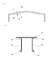
- a truss means a frame structure, in which several straight members are connected at joints to be arranged in the form of one or more triangles, and is used as a structural member in a roof framing or floor framing of a structure.
- the truss comprises an upper chord, a lower chord, a vertical member, and a diagonal member and is commonly used in a building or civil engineering structure.
- an axial stress occurs in the upper chord and the lower chord, if the center-to-center distance between the upper chord and the lower chord is greater, the axial stress is reduced, while the rigidity of the truss increases.
- the resisting force of the upper chord or lower chord in the truss, which is subjected to a compressive force, is determined by the slenderness ratio, and thus when the slenderness ratio of a main shaft by the length of the vertical member or the diagonal member is closer to the slenderness ratio of a countershaft by the buckling length of a compression member that compresses a member installed in an orthogonal direction in the truss, the efficiency of the member increases.
- angles are not suitable for a high load or long span truss and it is difficult to apply anticorrosive and fire retarding paints, which is problematic.
- the truss When the truss is made of a circular steel pipe, the truss is relatively lightweight, but the radius of gyration of two axes is the same, and thus the distance between subtrusses determines the resisting force of the member, which decreases the efficiency and reduces the bending strength. As a result, such a truss is not suitable for the high load or long span truss.
- a triangular steel pipe truss in which the upper chord or lower chord which is subjected to compression is made of two steel pipes, is widely used.
- the vertical members and diagonal members as branch pipes are welded to the upper chord or lower chord as a main pipe, and thus a high local stress is generated in the main pipe.
- the axial force of the vertical members or diagonal members is high, the application is limited, and the vertical members and diagonal members should be welded in a factory and then transported. As a result, the production cost increases and there are difficulties in the transportation.
- a H-section steel is generally used as the upper chord or lower chord, but in the case of the long span truss, the stress due to the truss weight is high, which reduces the efficiency, which is problematic.
- an object of the present invention is to provide a truss structure in which upper and lower pi parts, i.e., upper and lower chords, installed at the top and bottom of a truss have a pi-shaped cross section such that the center of the cross section is closer toward a flange to increase the efficiency of the cross section, thus increasing the rigidity.
- the bending strength is increased such that a high load truss can be supported and, at the same time, a long span truss can also be supported.
- an aspect of the present invention provides a pi truss structure, in which a bracing part is coupled to a coupling groove formed on the inside of each of pi-shaped upper and lower pi parts, wherein each of the pi parts is configured in a manner that web members in two rows are provided to face each other at right angles and coupled to the inside of a plate-shaped flange member such that a -shaped coupling groove is formed on the inside of the pi part in a longitudinal direction, wherein one side of each of the web members is formed on the flange member and the other side thereof is bent outward to form a reinforcing flange part, wherein the coupling grooves of the upper and lower pi parts are provided to face each other such that coupling members are coupled to the coupling grooves, respectively, and the bracing part is coupled to the coupling members.
- each of the web members facing the flange member is bent in the same shape as the reinforcing flange part to form an upper reinforcing flange part.
- one side of one of the web members at left and right sides facing the flange member is connected to one side of the other web member by a horizontal reinforcing member.
- the coupling member comprises a first coupling piece and a second coupling piece, which are coupled by welding, and the first coupling piece and the second coupling piece comprise coupling holes, respectively.
- reinforcing pieces are inserted into the inside of the coupling groove in a manner to face each other and coupled thereto by welding, and each of the reinforcing pieces has a shape selected from the group consisting of "-", " ", " ⁇ ” and " ⁇ ".
- the cross efficiency of the upper and lower pi parts, i.e., the upper and lower chords, installed at the top and bottom of a truss is increased such that the rigidity and bending strength can be increased, thus stably supporting a high load truss as well as a long span truss.
- the radius of gyration of countershafts of pi-shaped pi parts is increased to reduce the effect of lateral bucking and reduce the amount of members.
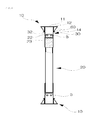
- a pi truss structure is configured in a manner that a bracing part 20 is coupled to a coupling groove 13, which is formed on the inside of each pi-shaped upper and lower pi parts 10 by a coupling member 30.
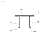
- the upper and lower pi parts 10 are configured in a manner that web members 12 in two rows, which are spaced at regular intervals, are coupled to the inside of a plate-shaped flange member 11 in a manner to face each other at right angles such that a -shaped coupling groove 13 is formed between them in a longitudinal direction.
- each of the web members 12 in two rows is in direct contact with the flange member 11 and coupled thereto by welding, and the other side of each of the welded web members 12 is bent outward to form a reinforcing flange part 14.
- the center of the pi-shaped cross section is closer toward the flange member 11, the center-to-center distance between the cross sections located at the top and bottom is maximized at the same height, and thus the stress is minimized, the strength is maximized, and the bent portion forms a flange, thus significantly increasing the bending strength.
- the web members 12, and the reinforcing flange parts 14 are configured such that the width varies depending on the length, it is possible to provide a more economical design of a truss structure in which the stress varies depending on its length.
- the coupling members 30 are respectively installed in the coupling grooves 13 formed on the inside of the upper and lower pi parts 10, and the upper and lower portions of each of the bracing parts 20 are coupled to the coupling members 30 located at the top and bottom.
- End plates 50 each having coupling holes H are coupled to both ends of each of the upper and lower pi parts 10 in a manner to face each other such that the upper and lower pi parts 10 can be continuously installed in the longitudinal direction.
- the bracing parts 20 are respectively coupled to the upper and lower pi parts 10 by means of the coupling members 30.
- a slit groove 21 is formed in the axial direction in the middle of both ends, respectively, and a third coupling piece 22 having coupling holes H is inserted into the slit groove 21 and coupled thereto by welding.
- Semicircular pieces 23 are welded to both sides of each of the third coupling pieces 22, which are inserted into both ends of the bracing part 20 and coupled thereto by welding, in a manner to face each other and coupled thereto by welding, thus increasing the strength of the coupling and, at the same time, preventing rainwater or foreign materials from entering from the outside.
- Each of the coupling members 30 allows the coupling groove 13 and the bracing part 20 to be connected by means of bolts B.
- a second coupling piece 32 is coupled to a first coupling piece 31 by welding, and the welded first coupling piece 31 and second coupling piece 32 are inserted and coupled to the inside of the coupling groove 13 by welding.
- Coupling holes H are formed in each of the first coupling piece 31 and the second coupling piece 32 such that the third coupling pieces 22, provided on the upper and lower portions of each of the bracing parts 20 and being in contact therewith are coupled thereto by means of bolts B.
- Two bracing parts 20 are coupled to the coupling members 30 provided on the upper pi part 10 and the coupling members 30 provided on the lower pi part 10.
- Triangular reinforcing pieces 60 are coupled to both sides of each of the web members 12, which are respectively formed on the upper and lower pi parts 10, by welding.
- Reinforcing pieces 40 each having a predetermined length are inserted into the inside of the coupling grooves 13, formed on the upper and lower pi parts 10, in a manner to face each other and coupled thereto by welding, thus partially controlling the strength.
- Each of the reinforcing pieces 40 has a shape selected from the group consisting of "-", “ “ , “ ⁇ ” and “ ⁇ ” such that the reinforcing pieces 40 can easily face each other in the coupling grooves 13 formed on the upper and lower pi parts 10. That is, in the regions where the bracing parts 20 are coupled to the upper and lower pi parts 10, the stress gradually increases or decreases depending on the length of the regions. Therefore, a region having a high stress is reinforced by the reinforcing pieces 40, and the other regions can bear the stress with non-reinforced cross sections.
- the web members 12 having the reinforcing flange parts 14 bent outward are arranged in two rows to face each other at right angles and coupled to the inside of the plate-shaped flange member 11, made of a steel plate, by welding.
- These web members 12 may be made of angles or formed by bending steel plates.
- the coupling member 30, to which the first coupling piece 31 and the second coupling piece 32 are coupled by welding is inserted into the inside of the coupling groove 13 formed in the longitudinal direction and coupled thereto by welding.
- the triangular reinforcing pieces 60 are coupled to both sides of each of the web members 12, which are respectively formed on the upper and lower pi parts 10, by welding.
- the reinforcing pieces 40 each having a length between the bracing parts 20 are inserted into the inside of the coupling grooves 13, formed on the upper and lower pi parts 10, in a manner to face each other and coupled thereto by welding, and then the end plates 50 each having the coupling holes H are coupled to both ends of each of the upper and lower pi parts 10 in a manner to face each other by welding.
- the coupling grooves 13, formed on the upper and lower pi parts 10, are arranged to face each other, and then each of the third coupling pieces 22, provided on the upper and lower portions of the bracing part 20 and facing the first coupling piece 31 and the second coupling piece 32, is coupled through the coupling holes H by means of bolts B.
- first coupling pieces 31 and the second coupling pieces 32 are open to have the same angle in both directions such that the bracing parts 20 are coupled in a zigzag manner, but the first coupling pieces 31 or the second coupling piece 32 may be arranged vertically such that one of two bracing parts 20 coupled to the coupling members 30 can be installed vertically.
- each of the web members 12 coupled to the inside of the flange member 11 is brought into direct contact with the flange member 11 at a right angle and coupled thereto by welding, but the one side of the web member 12 facing the flange member 11 may be bent in the same shape as the reinforcing flange part 14, thus forming an upper reinforcing flange part 15 as shown in FIG. 6A .
- the strength of the portion to which the flange member 11 is coupled by welding can be further increased.
- each of the web members 12 coupled to the inside of the flange member 11 is brought into direct contact with the flange member 11 at a right angle and coupled thereto by welding, but one side of one of the web members 12 at left and right sides facing the flange member 11 may be connected to one side of the other web member 12 by a horizontal reinforcing member 16 as shown in FIG. 6B .
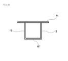
- each of the web members 12 coupled to the inside of the flange member 11 is brought in to direct contact with the flange member 11 at a right angle and coupled thereto by welding, but the other side of each of the web members 12 may be connected by another horizontal reinforcing member 16 as shown in FIG. 6C .
- a box-shaped space is created at the bottom of the flange member 11, thus obtaining more structurally stable strength.
Landscapes
- Engineering & Computer Science (AREA)
- Architecture (AREA)
- Civil Engineering (AREA)
- Structural Engineering (AREA)
- Health & Medical Sciences (AREA)
- Epidemiology (AREA)
- Life Sciences & Earth Sciences (AREA)
- Animal Behavior & Ethology (AREA)
- General Health & Medical Sciences (AREA)
- Public Health (AREA)
- Veterinary Medicine (AREA)
- Chemical & Material Sciences (AREA)
- Dispersion Chemistry (AREA)
- Mechanical Engineering (AREA)
- Rod-Shaped Construction Members (AREA)
- Joining Of Building Structures In Genera (AREA)
Applications Claiming Priority (2)
| Application Number | Priority Date | Filing Date | Title |
|---|---|---|---|
| KR1020110004554A KR101118608B1 (ko) | 2011-01-17 | 2011-01-17 | 파이 트러스 구조 |
| PCT/KR2011/010162 WO2012099346A2 (fr) | 2011-01-17 | 2011-12-27 | Structure de ferme utilisant un matériau présentant une section transversale en forme de pi en guise de membrure supérieure |
Publications (1)
| Publication Number | Publication Date |
|---|---|
| EP2666924A2 true EP2666924A2 (fr) | 2013-11-27 |
Family
ID=45840573
Family Applications (1)
| Application Number | Title | Priority Date | Filing Date |
|---|---|---|---|
| EP11856301.4A Withdrawn EP2666924A2 (fr) | 2011-01-17 | 2011-12-27 | Structure de ferme utilisant un matériau présentant une section transversale en forme de pi en guise de membrure supérieure |
Country Status (5)
| Country | Link |
|---|---|
| US (1) | US20130283728A1 (fr) |
| EP (1) | EP2666924A2 (fr) |
| KR (1) | KR101118608B1 (fr) |
| CN (1) | CN103314167A (fr) |
| WO (1) | WO2012099346A2 (fr) |
Cited By (1)
| Publication number | Priority date | Publication date | Assignee | Title |
|---|---|---|---|---|
| WO2021174323A1 (fr) * | 2020-03-02 | 2021-09-10 | Topico Locações De Galpões E Equipamentos Para Industrias S.A. | Structure en treillis, structure en arc et hangar |
Families Citing this family (15)
| Publication number | Priority date | Publication date | Assignee | Title |
|---|---|---|---|---|
| US9366040B2 (en) * | 2011-04-11 | 2016-06-14 | Easytrim Reveals Inc. | Wall panel trim reveal system and method |
| KR101512267B1 (ko) * | 2014-04-10 | 2015-04-14 | 최원복 | 건축구조물용 혼합 트러스형 용접부재 |
| CN205653980U (zh) * | 2015-10-30 | 2016-10-19 | 山东万斯达建筑科技股份有限公司 | 一种折板式桁架梁 |
| CN205653981U (zh) * | 2015-10-30 | 2016-10-19 | 张波 | 一种折板式桁架型钢 |
| USD815302S1 (en) * | 2016-05-16 | 2018-04-10 | Global Products International Group, Llc | Door jamb hinge plate locator |
| USD814660S1 (en) * | 2016-05-16 | 2018-04-03 | Global Products International Group, Llc | Door hinge plate locator |
| GB2567647B (en) * | 2017-10-18 | 2021-09-15 | Netting Services Northern Ltd | Structural beam |
| US11926977B2 (en) * | 2017-11-21 | 2024-03-12 | Allied Steel | Bridge truss system |
| BR102017026394B1 (pt) * | 2017-12-07 | 2022-08-02 | Carlos Alberto De Almeida Borges | Reforço de escudo |
| CN111962949B (zh) * | 2020-08-07 | 2024-06-21 | 北京工业大学 | 一种钢管混凝土柱-H型钢梁-钢支撑-π形连接件组合式中柱中部节点及作法 |
| US11499315B1 (en) * | 2021-06-10 | 2022-11-15 | Harsoyo Lukito | Connectors for use in truss system |
| KR102564471B1 (ko) * | 2021-08-14 | 2023-08-07 | (주)지아이에프 | 와렌트러스 형상으로 조립된 합성 격자거더 교량 |
| CN114411980B (zh) * | 2022-02-25 | 2023-08-18 | 东南大学 | 一种中空夹层内加劲外环板式钢管混凝土梁柱节点 |
| CN114482267B (zh) * | 2022-02-25 | 2024-04-09 | 东南大学 | 一种装配式中空波纹夹层钢管混凝土组合框架结构体系 |
| US20250052273A1 (en) * | 2023-08-09 | 2025-02-13 | Kamal BOUAOUAJA | Connecting element for a supporting structure and method for producing the same |
Family Cites Families (16)
| Publication number | Priority date | Publication date | Assignee | Title |
|---|---|---|---|---|
| US1523106A (en) * | 1920-06-28 | 1925-01-13 | Dornier Claudius | Sheet-metal girder |
| US1693660A (en) * | 1927-12-12 | 1928-12-04 | Norman B Obbard | Truss |
| US2514607A (en) * | 1946-02-07 | 1950-07-11 | Dravo Corp | Truss construction |
| GB1555618A (en) * | 1976-05-05 | 1979-11-14 | Dziewolski R | Rigid assembly joint |
| US4253210A (en) * | 1979-09-10 | 1981-03-03 | Andre Racicot | Metal truss structure |
| WO1992022716A1 (fr) * | 1991-06-19 | 1992-12-23 | Garry Randall Hart | Construction de batiment modulaire |
| JP3003770B2 (ja) * | 1995-09-11 | 2000-01-31 | 新日軽株式会社 | トラス用ラチス材の連結部構造 |
| GB9816180D0 (en) * | 1998-07-25 | 1998-09-23 | Kubik Leszek A | Space frames |
| US6079174A (en) * | 1998-12-04 | 2000-06-27 | Hufcor, Inc. | Wall panel having movable cap |
| JP2001146806A (ja) * | 1999-11-19 | 2001-05-29 | Sankyo Alum Ind Co Ltd | パネル支持装置 |
| US6553736B2 (en) * | 2000-12-26 | 2003-04-29 | Antonio Montanaro | Interlocking truss system |
| KR100416877B1 (ko) * | 2001-07-20 | 2004-01-31 | 한국건설기술연구원 | 개방형 단면을 갖는 철골보 및 이를 이용한 충복 내화형합성보 구조 |
| US8726606B2 (en) * | 2006-05-18 | 2014-05-20 | Paradigm Focus Product Development Inc. | Light steel trusses and truss systems |
| US20100180531A1 (en) | 2009-01-16 | 2010-07-22 | Vernon Eugene Arivett | Truss chord and truss system with ribs and radiuses |
| KR101003000B1 (ko) | 2010-08-13 | 2010-12-21 | 장광윤 | 더블티 트러스 구조 |
| KR101026118B1 (ko) | 2010-10-22 | 2011-04-05 | 최하정 | 지점부의 이차 모멘트에 대응하는 트러스구조물과 이의 제작방법 및 지점부의 이차 모멘트에 대응하는 트러스구조물을 이용한 트러스교와 이의 시공방법 |
-
2011
- 2011-01-17 KR KR1020110004554A patent/KR101118608B1/ko not_active Expired - Fee Related
- 2011-12-27 CN CN2011800651952A patent/CN103314167A/zh active Pending
- 2011-12-27 US US13/979,813 patent/US20130283728A1/en not_active Abandoned
- 2011-12-27 EP EP11856301.4A patent/EP2666924A2/fr not_active Withdrawn
- 2011-12-27 WO PCT/KR2011/010162 patent/WO2012099346A2/fr not_active Ceased
Non-Patent Citations (1)
| Title |
|---|
| See references of WO2012099346A3 * |
Cited By (1)
| Publication number | Priority date | Publication date | Assignee | Title |
|---|---|---|---|---|
| WO2021174323A1 (fr) * | 2020-03-02 | 2021-09-10 | Topico Locações De Galpões E Equipamentos Para Industrias S.A. | Structure en treillis, structure en arc et hangar |
Also Published As
| Publication number | Publication date |
|---|---|
| KR101118608B1 (ko) | 2012-02-27 |
| WO2012099346A3 (fr) | 2012-09-20 |
| WO2012099346A2 (fr) | 2012-07-26 |
| CN103314167A (zh) | 2013-09-18 |
| US20130283728A1 (en) | 2013-10-31 |
Similar Documents
| Publication | Publication Date | Title |
|---|---|---|
| EP2666924A2 (fr) | Structure de ferme utilisant un matériau présentant une section transversale en forme de pi en guise de membrure supérieure | |
| US20090007520A1 (en) | Modular Reinforced Structural Beam and Connecting Member System | |
| KR101156202B1 (ko) | 박스 단면형 박판 부재의 좌굴 보강 구조 | |
| KR102079008B1 (ko) | 단부모멘트 및 휨 저항력이 보강된 보와 기둥의 이-지(ez) 결합구조 | |
| KR20140051434A (ko) | 스팬이 넓은 정적 구조물 | |
| CN110067185B (zh) | 一种钢管-钢板组合腹板钢混组合箱梁 | |
| CA2366099C (fr) | Systeme de fermes a emboitement | |
| US10648167B2 (en) | Slotted joist seat structure and methods of designing and building the structure | |
| US11326337B2 (en) | Building structure, building, and building method | |
| JP2667129B2 (ja) | 鋼・コンクリート複合桁 | |
| KR101373262B1 (ko) | 연결판 교차식 콘크리트 충전 강관기둥 | |
| KR20140115894A (ko) | 변단면 플랜지 철골 보를 이용한 철골 라멘 골조 | |
| KR101825580B1 (ko) | 철골-프리캐스트 콘크리트 합성보 | |
| CN210263635U (zh) | 一种全螺栓连接的桁架式型钢混凝土梁 | |
| CN109610640B (zh) | 一种基于复合柱肢的门式刚架连接结构 | |
| KR101431475B1 (ko) | 지붕보의 횡좌굴 방지수단이 구비된 단위 지붕틀 | |
| KR101732724B1 (ko) | 조립광폭튜브 플랜지를 갖는 공장용 하이브리드 골조 | |
| CN106088755A (zh) | 一种预制装配式大型钢结构矩形仓及矩形群仓 | |
| JP2022102437A (ja) | 連続構造梁及びこれを使用した屋根構造 | |
| CN219411508U (zh) | 一种装配式冷弯薄壁型钢平面桁架结构 | |
| CN119711785B (zh) | 一种装配式钢管桁架加装电梯井结构的施工方法 | |
| JP2007113302A (ja) | 合成梁構造 | |
| KR101003000B1 (ko) | 더블티 트러스 구조 | |
| CN212001911U (zh) | 一种新型钢结构 | |
| CN120622305A (zh) | 下弦为带牛腿吊车梁的吊车桁架结构 |
Legal Events
| Date | Code | Title | Description |
|---|---|---|---|
| PUAI | Public reference made under article 153(3) epc to a published international application that has entered the european phase |
Free format text: ORIGINAL CODE: 0009012 |
|
| 17P | Request for examination filed |
Effective date: 20130801 |
|
| AK | Designated contracting states |
Kind code of ref document: A2 Designated state(s): AL AT BE BG CH CY CZ DE DK EE ES FI FR GB GR HR HU IE IS IT LI LT LU LV MC MK MT NL NO PL PT RO RS SE SI SK SM TR |
|
| DAX | Request for extension of the european patent (deleted) | ||
| STAA | Information on the status of an ep patent application or granted ep patent |
Free format text: STATUS: THE APPLICATION HAS BEEN WITHDRAWN |
|
| 18W | Application withdrawn |
Effective date: 20141210 |