EP2667005A2 - Système inverseur de poussée - Google Patents
Système inverseur de poussée Download PDFInfo
- Publication number
- EP2667005A2 EP2667005A2 EP13165423.8A EP13165423A EP2667005A2 EP 2667005 A2 EP2667005 A2 EP 2667005A2 EP 13165423 A EP13165423 A EP 13165423A EP 2667005 A2 EP2667005 A2 EP 2667005A2
- Authority
- EP
- European Patent Office
- Prior art keywords
- sleeve
- linear electric
- electric motor
- electric motors
- move
- Prior art date
- Legal status (The legal status is an assumption and is not a legal conclusion. Google has not performed a legal analysis and makes no representation as to the accuracy of the status listed.)
- Granted
Links
- 238000000034 method Methods 0.000 claims abstract description 43
- 238000012544 monitoring process Methods 0.000 claims description 2
- 230000008569 process Effects 0.000 description 25
- 238000012423 maintenance Methods 0.000 description 12
- 238000010586 diagram Methods 0.000 description 10
- 238000004891 communication Methods 0.000 description 8
- 230000007246 mechanism Effects 0.000 description 7
- 230000008859 change Effects 0.000 description 6
- 239000012530 fluid Substances 0.000 description 4
- 239000003381 stabilizer Substances 0.000 description 3
- 239000007789 gas Substances 0.000 description 2
- 238000012986 modification Methods 0.000 description 2
- 230000004048 modification Effects 0.000 description 2
- 230000004044 response Effects 0.000 description 2
- 230000001133 acceleration Effects 0.000 description 1
- 230000000903 blocking effect Effects 0.000 description 1
- 238000006243 chemical reaction Methods 0.000 description 1
- 230000000694 effects Effects 0.000 description 1
- 230000005672 electromagnetic field Effects 0.000 description 1
- 230000003993 interaction Effects 0.000 description 1
- 238000002955 isolation Methods 0.000 description 1
- 238000004519 manufacturing process Methods 0.000 description 1
- 230000009347 mechanical transmission Effects 0.000 description 1
- 239000013307 optical fiber Substances 0.000 description 1
- 238000009428 plumbing Methods 0.000 description 1
- 230000001681 protective effect Effects 0.000 description 1
- 239000004065 semiconductor Substances 0.000 description 1
- 239000013589 supplement Substances 0.000 description 1
Images


Classifications
-
- F—MECHANICAL ENGINEERING; LIGHTING; HEATING; WEAPONS; BLASTING
- F02—COMBUSTION ENGINES; HOT-GAS OR COMBUSTION-PRODUCT ENGINE PLANTS
- F02K—JET-PROPULSION PLANTS
- F02K1/00—Plants characterised by the form or arrangement of the jet pipe or nozzle; Jet pipes or nozzles peculiar thereto
- F02K1/54—Nozzles having means for reversing jet thrust
- F02K1/64—Reversing fan flow
- F02K1/70—Reversing fan flow using thrust reverser flaps or doors mounted on the fan housing
- F02K1/72—Reversing fan flow using thrust reverser flaps or doors mounted on the fan housing the aft end of the fan housing being movable to uncover openings in the fan housing for the reversed flow
-
- F—MECHANICAL ENGINEERING; LIGHTING; HEATING; WEAPONS; BLASTING
- F01—MACHINES OR ENGINES IN GENERAL; ENGINE PLANTS IN GENERAL; STEAM ENGINES
- F01D—NON-POSITIVE DISPLACEMENT MACHINES OR ENGINES, e.g. STEAM TURBINES
- F01D17/00—Regulating or controlling by varying flow
- F01D17/20—Devices dealing with sensing elements or final actuators or transmitting means between them, e.g. power-assisted
- F01D17/22—Devices dealing with sensing elements or final actuators or transmitting means between them, e.g. power-assisted the operation or power assistance being predominantly non-mechanical
- F01D17/24—Devices dealing with sensing elements or final actuators or transmitting means between them, e.g. power-assisted the operation or power assistance being predominantly non-mechanical electrical
-
- F—MECHANICAL ENGINEERING; LIGHTING; HEATING; WEAPONS; BLASTING
- F02—COMBUSTION ENGINES; HOT-GAS OR COMBUSTION-PRODUCT ENGINE PLANTS
- F02K—JET-PROPULSION PLANTS
- F02K1/00—Plants characterised by the form or arrangement of the jet pipe or nozzle; Jet pipes or nozzles peculiar thereto
- F02K1/54—Nozzles having means for reversing jet thrust
- F02K1/76—Control or regulation of thrust reversers
- F02K1/763—Control or regulation of thrust reversers with actuating systems or actuating devices; Arrangement of actuators for thrust reversers
-
- F—MECHANICAL ENGINEERING; LIGHTING; HEATING; WEAPONS; BLASTING
- F05—INDEXING SCHEMES RELATING TO ENGINES OR PUMPS IN VARIOUS SUBCLASSES OF CLASSES F01-F04
- F05D—INDEXING SCHEME FOR ASPECTS RELATING TO NON-POSITIVE-DISPLACEMENT MACHINES OR ENGINES, GAS-TURBINES OR JET-PROPULSION PLANTS
- F05D2220/00—Application
- F05D2220/70—Application in combination with
- F05D2220/76—Application in combination with an electrical generator
- F05D2220/77—Application in combination with an electrical generator of the linear type
-
- F—MECHANICAL ENGINEERING; LIGHTING; HEATING; WEAPONS; BLASTING
- F05—INDEXING SCHEMES RELATING TO ENGINES OR PUMPS IN VARIOUS SUBCLASSES OF CLASSES F01-F04
- F05D—INDEXING SCHEME FOR ASPECTS RELATING TO NON-POSITIVE-DISPLACEMENT MACHINES OR ENGINES, GAS-TURBINES OR JET-PROPULSION PLANTS
- F05D2250/00—Geometry
- F05D2250/40—Movement of components
- F05D2250/41—Movement of components with one degree of freedom
-
- F—MECHANICAL ENGINEERING; LIGHTING; HEATING; WEAPONS; BLASTING
- F05—INDEXING SCHEMES RELATING TO ENGINES OR PUMPS IN VARIOUS SUBCLASSES OF CLASSES F01-F04
- F05D—INDEXING SCHEME FOR ASPECTS RELATING TO NON-POSITIVE-DISPLACEMENT MACHINES OR ENGINES, GAS-TURBINES OR JET-PROPULSION PLANTS
- F05D2270/00—Control
- F05D2270/60—Control system actuates means
- F05D2270/62—Electrical actuators
-
- Y—GENERAL TAGGING OF NEW TECHNOLOGICAL DEVELOPMENTS; GENERAL TAGGING OF CROSS-SECTIONAL TECHNOLOGIES SPANNING OVER SEVERAL SECTIONS OF THE IPC; TECHNICAL SUBJECTS COVERED BY FORMER USPC CROSS-REFERENCE ART COLLECTIONS [XRACs] AND DIGESTS
- Y02—TECHNOLOGIES OR APPLICATIONS FOR MITIGATION OR ADAPTATION AGAINST CLIMATE CHANGE
- Y02T—CLIMATE CHANGE MITIGATION TECHNOLOGIES RELATED TO TRANSPORTATION
- Y02T50/00—Aeronautics or air transport
- Y02T50/60—Efficient propulsion technologies, e.g. for aircraft
Definitions
- the present disclosure relates generally to aircraft and, in particular, to controlling movement aircraft. Still more particularly, the present disclosure relates to a method and apparatus for reversing thrust in an aircraft using a thrust reverser system.
- the passenger aircraft When a typical commercial or military sized aircraft lands, the passenger aircraft may land at a speed from about 140 mph to about 160 mph. These aircraft may weigh from about 80,000 pounds to over 800,000 pounds. Reducing the velocity of an aircraft of these weights and at these speeds may be challenging. Therefore, these aircraft typically require robust systems that can handle the force of slowing down and stopping the passenger aircraft.
- reducing the speed of the aircraft to bring the aircraft to a stopped position may involve many different mechanisms.
- one type of system used to reduce the speed of the aircraft is a landing gear system. These landing gear systems use breaks to slow down the aircraft.
- the aircraft brakes are designed to absorb large amounts of energy to reduce the speed of the aircraft.
- Control surface systems may be used to reduce the speed of the aircraft after landing.
- ground spoilers may be deployed after the aircraft lands to slow down the speed of the aircraft.
- Thrust reverser systems are employed on engines to change the direction of thrust.
- the direction of thrust is changed from a direction aft of the aircraft to a direction toward the front or forward part of the aircraft.
- Thrust reverser systems may include sections such as sleeves that open at the rear of an engine. With a thrust reverser system, a sleeve covering cascades may be moved in an aftward direction.
- the cascades are an array of structures that direct airflow in an engine. These cascades, when exposed, may direct airflow out through the side of the engine and in a forward direction rather than the airflow flowing in an aft direction out of the engine.
- blockers or other structures when the sleeve is moved, blockers or other structures also may block the opening through which the exhaust typically flows out of the engine. These blocking structures along with the cascades may direct air in the forward direction to reduce the speed of the aircraft.
- sleeves and other components are typically moved using hydraulic systems, motors, actuators, valves and plumbing components that add undesired weight and complexity to the aircraft. With the number of components used to move the sleeves, maintenance may be more time consuming and expensive than desired. Also, the aircraft and the engine may weigh more and may be more expensive to manufacture than desired.
- the invention involves an apparatus that includes a sleeve configured to move between a first position and a second position, wherein the sleeve exposes a cascade when in the second position; at least one linear electric motor connected to the sleeve and configured to move the sleeve between the first position and the second position; and a controller configured to control operation of the at least one linear electric motor to move the sleeve between the first position and the second position.
- the controller is configured to control operation of the at least one linear electric motor to move the sleeve between the first position and the second position with a desired number of speeds.
- the apparatus may include a sensor system configured to measure a position of the sleeve.
- the controller may be configured to synchronize the at least one linear electric motor to move the sleeve.
- the controller may be configured to compensate for a linear electric motor in the at least one linear electric motor not functioning as desired.
- the controller may be further configured to control operation of a group of remaining linear electric motors in the at least one linear electric motor to move the sleeve between the first position and the second position taking into account load changes caused by the linear electric motor to maintain a load on the group of remaining linear electric motors below a selected load.
- the controller may cause the linear electric motor to operate in a mode in which a member that is connected to the sleeve floats.
- the controller may be configured to stop the sleeve in at least one of the first position and the second position.
- the controller may be configured to reduce a speed of the at least one linear electric motor while moving the sleeve between the first position and the second position to maintain a load on the at least one linear electric motor caused by moving the sleeve below a selected
- the invention includes a thrust reverser system comprising a sleeve configured to move between a first position and a second position, wherein the sleeve exposes a cascade when in the second position; and at least one linear electric motor having a base end connected to an engine structure and a member directly connected to the sleeve and configured to move the sleeve between the first position and the second position.
- the thrust reverser system may include a plurality of linear electric motors having a base end connected to an engine structure; and a member directly connected to the sleeve and configured to move the sleeve between the first position and the second position.
- the thrust reverser system may also include a sensor system configured to detect a load on the at least one linear electric motor while moving the sleeve and measure a position of the sleeve; and a controller configured to control operation of the at least one linear electric motor to move the sleeve between the first position and the second position and control a speed at which the at least one linear electric motor moves the sleeve to maintain a load on the at least one linear electric motor below a selected load.
- a controller can be configured to stop the sleeve in at least one of the first position and the second position.
- a controller can be configured to compensate for a linear electric motor in the at least one linear electric motor not functioning as desired.
- the invention involves a method for operating a thrust reverser system for an aircraft, the method includes moving a sleeve on an engine in the thrust reverser system from a first position to a second position using a linear electric motor connected to the sleeve and to a structure of the engine, wherein the moving of the sleeve to a second position exposes a cascade such that exhaust gasses generated by the engine pass through the cascade.
- the method may also include moving the sleeve from the first position to the second position using a plurality of linear electric motors.
- the method may also include determining whether a load on a plurality of linear electric motors is greater than a selected load; and adjusting a speed of the plurality of linear electric motors to reduce the load on the plurality of linear electric motors when the load is equal to or greater than the selected load.
- the selected load may be one that is greater than a desired load for the plurality of linear electric motors. Operation of the linear electric motor may be controlled by a controller.
- Moving the sleeve on the engine in the thrust reverser system from the first position to the second position using the plurality of linear electric motors connected to the sleeve may involve sending a command to the plurality of linear electric motors to move the sleeve in a direction from the first position towards the second position; monitoring a position of the sleeve; and halting operation of the plurality of linear electric motors to halt movement of the sleeve when the second position is reached.
- an apparatus comprises a sleeve, at least one linear electric motor connected to the sleeve, and a controller.
- the sleeve is configured to move between a first position and a second position.
- the sleeve exposes a cascade when in the second position.
- the at least one linear electric motor is configured to move the sleeve between the first position and the second position.
- the controller is configured to control operation of the at least one linear electric motor to move the sleeve between the first position and the second position.
- a thrust reverser system comprises a sleeve and at least one linear electric motor.
- the sleeve is configured to move between a first position and a second position.
- the sleeve exposes a cascade when in the second position.
- the at least one linear electric motor has a base end connected to an engine structure and a member directly connected to the sleeve.
- the at least one linear electric motor is configured to move the sleeve between the first position and the second position.
- a method for operating a thrust reverser system for an aircraft is present.
- a sleeve on an engine in the thrust reverser system is moved from a first position to a second position using a linear electric motor connected to the sleeve and to the structure of the engine.
- the sleeve is moved to a second position and exposes a cascade such that exhaust gasses generated by the engine pass through the cascade.
- the illustrative embodiments recognize and take into account one or more different considerations.
- hydraulic systems used to control a sleeve for a thrust reverser system include a reservoir, a hydraulic fluid pump, directional control valves, isolation valves, tubes, seals, mechanical sink shafts, sink locks, position sensors, and other components. These different components add to the complexity of a hydraulic system used to move the sleeve in a thrust reverser system.
- the illustrative embodiments recognize and take into account that the use of interfaces such as mechanical linkages may add to the complexity of a mechanism used to move sleeves in a thrust reverser system.
- the illustrative embodiments also recognize and take into account that a hydraulic system also may not provide as much precision as desired in moving a thrust reverser.
- the illustrative embodiments also recognize and take into account that in addition to the complexity, hydraulic systems may have increased maintenance needs and leaks that may result in undesired fluids entering different components of the engine that also may require maintenance.
- electro-mechanical systems may be used in place of hydraulic systems. These electro-mechanical systems, however, still include gears and other components as an interface between the motor and the sleeve.
- the illustrative embodiments also recognize and take into account that with currently used electro-mechanical motors, the gears and other components may require maintenance more often than desired.
- the illustrative embodiments provide a method and apparatus for moving a sleeve in a thrust reverser system.
- mechanical interfaces between the motor and the sleeve are not used.
- an electric motor may be directly connected to the sleeve.
- the electric motor used to move the sleeve is a linear electric motor and, in particular, a digital linear electric motor.
- aircraft 100 has wing 102 and wing 104 attached to body 106.
- Aircraft 100 includes engine 108 attached to wing 102 and engine 110 attached to wing 104.
- Body 106 has tail section 112. Horizontal stabilizer 114, horizontal stabilizer 116, and vertical stabilizer 118 are attached to tail section 112 of body 106.
- Aircraft 100 is an example of an aircraft in which thrust reverser system 120 may be implemented in accordance with an illustrative embodiment.
- a thrust reverser system 120 may be implemented in engine 108 and engine 110.
- Thrust reverser system 120 may redirect the flow of engine exhaust gases and effectively change the thrust generated by engine 108 and engine 110 from an aft direction as indicated by arrow 122 to a forward direction as indicated by arrow 124.
- thrust reverser system 120 may be implemented in a manner that reduces maintenance as compared to hydraulic systems used in currently available thrust reverser systems. Further, the illustrative examples may be implemented in a manner that reduces the use of complex mechanical linkages, complex mechanical transmissions, or both.
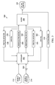
- thrust reverser system 200 is an example of a thrust reverser system that may be used to implement thrust reverser system 120 in aircraft 100 in Figure 1 .
- thrust reverser system 200 may be associated with engine 202.
- association is a physical association in these depicted examples.
- a first component, thrust reverser system 200 may be considered to be associated with a second component, engine 202, by being secured to the second component, bonded to the second component, mounted to the second component, welded to the second component, fastened to the second component, and/or connected to the second component in some other suitable manner.
- the first component also may be connected to the second component using a third component.
- the first component may also be considered to be associated with the second component by being formed as part of and/or an extension of the second component.
- Thrust reverser system 200 may operate to change the direction of thrust 204 from substantially aft 206 to substantially forward 208. Thrust 204 is generated by airflow through engine 202 in these illustrative examples. Airflow may include other gases as well as air that enter engine 202.
- thrust reverser system 200 includes number of sleeves 210, movement system 212, and controller 214.
- Number of sleeves 210 is associated with engine 202 and may move to change the direction of thrust 204.
- Movement system 212 is configured to move number of sleeves 210 on engine 202.
- the operation of movement system 212 is controlled by controller 214.
- Controller 214 may be implemented using hardware, software, or a combination of the two.
- the operations performed by the components may be implemented in the program code configured to be run on a processor unit.
- the hardware may include circuits that operate to perform the operations in the components.
- the hardware for controller 214 may take the form of a computer system, a processor unit, a circuit system, an integrated circuit, an application specific integrated circuit (ASIC), a programmable logic device, or some other suitable type of hardware configured to perform a number of operations.
- ASIC application specific integrated circuit
- the device is configured to perform the number of operations.
- the device may be reconfigured at a later time or may be permanently configured to perform the number of operations.
- Examples of programmable logic devices include, for example, a programmable logic array, a programmable array logic, a field programmable logic array, a field programmable gate array, and other suitable hardware devices.
- the processes may be implemented in organic components integrated with inorganic components and/or may be comprised entirely of organic components excluding a human being. For example, the processes may be implemented as circuits in organic semiconductors.
- Controller 214 is in communication with movement system 212 using number of communications links 216.
- number of communications links 216 is one or more communications links.
- number of communications links 216 may be comprised of at least one of a wire, an optical fiber, a wireless link, and other suitable types of communications links.
- the phrase "at least one of”, when used with a list of items, means different combinations of one or more of the listed items may be used and only one of each item in the list may be needed.
- "at least one of item A, item B, and item C" may include, without limitation, item A or item A and item B. This example also may include item A, item B, and item C, or item B and item C.
- "at least one of” may be, for example, without limitation, two of item A, one of item B, and ten of item C; four of item B and seven of item C; and other suitable combinations.
- sleeve 218 is a sleeve within number of sleeves 210.
- Sleeve 218 is moveable between first position 220 and second position 222. Movement of sleeve 218 is controlled by movement system 212. Further, movement system 212 also may maintain the position of sleeve 218 when sleeve 218 is not moving. This position may be first position 220, second position 222, or some position between the two.
- Cascades 224 are structures that direct airflow. Cascades 224 may take various forms. For example, cascades 224 may be airfoils, channels through a structure, or other suitable types of structures.
- cascades 224 are exposed.
- cascades 224 are configured to direct airflow in a direction that is substantially forward 208 when sleeve 218 is in second position 222.
- cascades 224 may be partially exposed such that cascades 224 direct thrust 204 in a direction that is substantially forward 208. In this position, thrust 204 also may still be directed in a direction that is substantially aft 206.
- movement system 212 includes number of electric motors 226.
- number of electric motors 226 may take the form of number of linear electric motors 228.
- An electric motor is a hardware device that converts electrical energy into mechanical energy.
- a linear electric motor is an electric motor that generates movement that is linear as opposed to rotational movement. In other words, a linear electric motor may cause movement along a straight line.
- Number of electric motors 226 may be connected to structure 230 in engine 202 and to sleeve 218. As depicted, the connection is a direct connection.
- a direct connection is a connection that does not use linkages, gear systems, or other moving parts.
- the direct connection may include other components between number of electric motors 226 and sleeve 218, structure 230, or both that are non-moving parts in these illustrative examples. In particular, these are non-moving parts that are used to aid in moving sleeve 218 between first position 220 and second position 222.
- controller 214 is configured to control operation of number of electric motors 226 when moving sleeve 218.
- Number of electric motors 226 may move sleeve 218 at number of speeds 232 and with number of loads 234. In other words, depending on the alignment or positioning of number of electric motors 226, different electric motors in number of electric motors 226 may operate at different speeds when moving sleeve 218.
- connection of number of electric motors 226 to sleeve 218 and other sources of load may result in number of electric motors 226 having number of loads 234 applied during movement of sleeve 218.
- Different loads in number of loads 234 may be different for different electric motors in number of electric motors 226 when moving sleeve 218.
- Number of loads 234 may be on number of electric motors 226 may be detected by sensor system 242.
- controller 214 is configured to send commands 236 over number of communications links 216 to number of electric motors 226 to cause number of electric motors 226 to move to number of positions 238.
- the movement of electric motors 226 to number of positions 238 is configured to cause movement of sleeve 218 between first position 220 and second position 222 or to other positions in between the two.
- Number of electric motors 226 may send back information such as number of loads 234 and number of positions 238 to controller 214.
- portions of sensor system 242 may be located in or part of number of electric motors 226. This information may be used by controller 214 to control the operation of number of electric motors 226. Controller 214 may use this information to synchronize number of electric motors 226 to move sleeve 218. In other words, operation of number of electric motors 226 may be controlled such that sleeve 218 moves between first position 220 and second position 222 in a desired manner. This synchronization may reduce loads on sleeve 218, number of electric motors 226, or both.
- controller 214 may control number of speeds 232 such that number of loads 234 does not exceed selected load 240.
- different types of number of electric motors 226 may be used.
- number of electric motors 226 may be selected to operate with number of loads 234 that is less than selected load 240.
- controller 214 may send commands 236 to control operation of number of electric motors 226 such that number of loads 234 on number of electric motors 226 is less than selected load 240.
- number of loads 234 on number of electric motors 226 may be substantially the same for most of the movement of sleeve 218.
- a spike in these loads may increase above the loads designed for number of electric motors 226. In other words, the increase in the load may only be for a short distance or time.
- controller 214 may control number of speeds 232 such that number of loads 234 remains below selected load 240 such that the spike does not increase wear on number of electric motors 226.
- slowing number of speeds 232 may maintain number of loads 234 at a level below selected load 240.
- smaller electric motors may be selected for number of electric motors 226 than would be needed if number of electric motors 226 is selected to take into account spikes in number of loads 234.
- thrust reverser system 200 also may include sensor system 242.
- Sensor system 242 is associated with number of sleeves 210.
- sensor system 242 may comprise number of sensors 244 in which each sensor in number of sensors 244 is configured to monitor a sleeve in number of sleeves 210.
- Sensor 246 in number of sensors 244 in sensor system 242 may, for example, detect position 248 of sleeve 218.
- Position 248 identified by sensor system 242 may supplement number of positions 238 sent from number of electric motors 226 to controller 214. In some cases, position 248 may be used in place of number of positions 238.
- thrust reverser system 200 With thrust reverser system 200, less maintenance may be needed with the use of number of electric motors 226. Further, the connection of number of electric motors 226 without the use of components such as linkages, gears, and other moving components that translate movement from number of electric motors 226 to movement of sleeve 218 may reduce the complexity of thrust reverser system 200. Further, with the use of number of electric motors 226, issues associated with fluids and other components in hydraulics systems may be reduced or avoided.
- number of electric motors 226 may provide for more precision in moving sleeve 218. Also, the size and weight of number of electric motors 226 may be reduced through the use of selected load 240 as a threshold to manage number of loads 234 encountered by number of electric motors 226 when moving sleeve 218.
- thrust reverser system 200 in Figure 2 is not meant to imply physical or architectural limitations to the manner in which a thrust reverser system may be implemented.
- Other components in addition to or in place of the ones illustrated may be used. Some components may be unnecessary.
- the blocks are presented to illustrate some functional components. One or more of these blocks may be combined, divided, or combined and divided into different blocks when implemented in an illustrative embodiment.
- thrust reverser system 200 may include other components in addition to the ones depicted in Figure 2 .
- block structures may be present in thrust reverser system 200 that are configured to reduce or block airflow toward a direction that is aft 206. These structures may increase airflow through cascades 224 to increase thrust in a direction that is substantially forward 208.
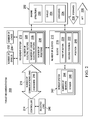
- FIG. 3 an illustration of a control diagram for a thrust reverser system is depicted in accordance with an illustrative embodiment.
- a control diagram for thrust reverser system 300 is depicted.
- Thrust reverser system 300 is one example of an implementation for thrust reverser system 200 shown in a conceptual block form in Figure 2 .
- Thrust reverser system 300 includes controller 302, summing node 303, linear electric motor 304, linear electric motor 306, sleeve 308, and position sensor 310.
- Controller 302 is configured to receive inputs, such as desired speed 312 and desired position 314.
- Desired speed 312 is a speed that is desired for the movement of sleeve 308 to desired position 314.
- Desired position 314 may be a position such as first position 220 and second position 222 in Figure 2 , or any position in between the two.
- controller 302 In response to receiving these inputs, controller 302 sends commands to linear electric motor 304 and linear electric motor 306. Controller 302 is an example of controller 214 in Figure 2 . Linear electric motor 304 and linear electric motor 306 are examples of linear electric motors in number of linear electric motors 228 in Figure 2 . These commands are commands identifying acceleration for these linear electric motors. These commands may be varied during movement of sleeve 308 to maintain a desired load on the linear electric motors.
- Sleeve 308 is an example of sleeve 218 in number of sleeves 210 in Figure 2 .
- feedback may be received through position detector 316 and load cell 318 for linear electric motor 304.
- Feedback also may be received through position detector 320 and load cell 322 for linear electric motor 306.
- Position detector 316 and position detector 320 send information about the position of linear electric motor 304 and linear electric motor 306, respectively.
- Load cell 318 and load cell 322 send information about loads for linear electric motor 304 and linear electric motor 306, respectively. This information about position and load are received by controller 302.
- position detector 316 and load cell 318 may be part of linear electric motor 304 or may be separate sensors.
- position detector 320 and load cell 322 may be part of linear electric motor 306 or separate components depending on the particular implementation.
- the load information is used to ensure that the load does not exceed a desired load for the linear electric motors. Further, the load information also is used to maintain a desired load on the linear electric motors. For example, the load may be maintained at a consistent level in these illustrative examples.
- the position information is used to identify the current position of each linear electric motor.
- the position of the linear electric motor may correlate to actual position 324 of sleeve 308.
- sleeve 308 may be moved to desired position 314.
- moving sleeve 308 past desired position 314 also may be reduced or avoided through the information received from position detector 316 and position detector 320.
- sleeve 308 may not move to an undesired position that may cause an undesired load on other components in the engine.
- controller 302 also may be configured to maintain linear electric motor 304 and linear electric motor 306 in desired position 314 when actual position 324 reaches desired position 314. In other words, linear electric motor 304 and linear electric motor 306 may be locked to prevent inadvertent movement of sleeve 308 when sleeve 308 is in desired position 314.
- linear electric motor 304 and linear electric motor 306 may be commanded to maintain a particular position.
- a locking mechanism may physically lock linear electric motor 304 and linear electric motor 306 into a particular position.
- movement by linear electric motor 304 and linear electric motor 306 may be prevented by a locking mechanism that engages sleeve 308 instead of linear electric motor 304 and linear electric motor 306.
- the locking mechanism (not shown) may be a physical locking mechanism external to linear electric motor 304 and linear electric motor 306 or may be one internal to linear electric motor 304 and linear electric motor 306 that is controlled by controller 214. In this manner, controller 214 may stop the sleeve 218 in at least one of the first position 220 and the second position 222.
- position sensor 310 is a sensor configured to identify actual position 324 of sleeve 308.
- Position sensor 310 is an example of sensor 246 in number of sensors 244 in sensor system 242 in Figure 2 .
- Actual position 324 is sent back to controller 302.
- Actual position 324 is compared to desired position 314 and may be used as another piece of information to determine whether sleeve 308 has reached desired position 314.
- Actual position 324 provided by position sensor 310 may be summed at summing node 303. In this manner, when the difference between desired position 314 and actual position 324 reaches zero, sleeve 308 is considered to be at desired position 314. In other illustrative examples, this comparison may be made within controller 302.
- linear electric motor 304 and linear electric motor 306 may be identified and taken into account. For example, if linear electric motor 306 does not move as desired, linear electric motor 306 may be commanded to "float". In other words, linear electric motor 306 may change position in response to movement of sleeve 308 without actively moving. In this example, linear electric motor 304 may be commanded to move to desired position 314 through commands sent by controller 302.
- thrust reverser system 300 may operate to move sleeve 308 to desired position 314 even though linear electric motor 306 does not operate as desired.
- This type of adaptability may reduce undesired operation, undesired wear, or other undesired effects that may occur by continuing to use linear electric motor 306.
- control diagram for thrust reverser system 300 is not meant to limit the manner in which different thrust reverser systems may be implemented.
- other thrust reverser systems may have other numbers of linear electric motors connected to sleeve 308.
- three, four, or some other number of linear electric motors may be used.
- position sensor 310 may be omitted and actual position 324 of sleeve 308 may be identified through position information for linear electric motor 304 and linear electric motor 306.
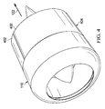
- FIG. 4 an illustration of an engine for an aircraft is depicted in accordance with an illustrative embodiment.
- engine 110 for aircraft 100 is shown.
- engine 110 includes sleeve 400 and sleeve 402.
- sleeve 400 and sleeve 402 are shown in first position 404.
- first position 404 is a substantially closed position.
- thrust is in the direction of arrow 122 which is an aft direction with respect to aircraft 100 in Figure 1 .
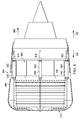
- FIG. 5 an illustration of an engine for an aircraft is depicted in accordance with an illustrative embodiment.
- sleeve 400 and sleeve 402 are shown in second position 500.
- Second position 500 is a substantially open position. In this position, cascades 502 are exposed. In this position, cascades 502 direct airflow in the direction of arrow 124 toward the front of aircraft 100 in Figure 1 .
- movement system 504 is configured to move sleeve 400 and sleeve 402 into second position 500 from first position 404. Further, movement system 504 also may move these sleeves back to first position 404 from second position 500.
- movement system 504 includes linear electric motor 600, linear electric motor 602, linear electric motor 604, linear electric motor 606, linear electric motor 608, and linear electric motor 610.
- Linear electric motors 600, 602, and 604 are connected to sleeve 400 (not shown).
- Linear electric motors 606, 608, and 610 are connected to sleeve 402.
- linear electric motors are also connected to a structure in engine 110.
- the structure may be a cascade support ring, an engine housing, or other suitable structure.
- linear electric motor 600 has base 612 and member 614.
- Linear electric motor 602 has base 616 and member 618.
- Linear electric motor 604 has base 620 and member 622.
- Linear electric motor 606 has base 624 and member 626.
- Linear electric motor 608 has base 628 and member 630.
- Linear electric motor 610 has base 632 and member 634.
- the bases are connected to the structure in engine 110 while the members are connected to sleeve 400 and sleeve 402.
- the members are moveable members and may be moved to different positions to cause sleeve 400 and sleeve 402 to move between first position 404 in Figure 4 and second position 500 in Figure 5 .
- base 612 of linear electric motor 600, base 616 of linear electric motor 602, and base 620 of linear electric motor 604 are connected to wiring harness 636.
- base 624 of linear electric motor 606, base 628 of linear electric motor 608, and base 632 of linear electric motor 610 are connected to wiring harness 638.
- These wiring harnesses may be connected to a controller to provide communications between the controller and these linear electric motors.
- a wiring harness may include one or more wires inside a protective cover.
- FIG. 7 an illustration of an exposed view of an engine with a movement system configured to move a sleeve for a thrust reverser system is depicted in accordance with an illustrative embodiment.
- movement system 504 is shown installed in engine 110.
- linear electric motor 600 linear electric motor 602, and linear electric motor 604 are depicted.
- base 612, base 616, and base 620 are connected to cascade ring 700.
- Member 614, member 618, and member 622 are connected to sleeve 400. These connections are not visible in this exposed view.
- sleeve 400 is in first position 404 such that cascades 502 are not exposed.
- First position 404 is a closed position in this example. In this position, thrust is substantially in the direction of arrow 122 as opposed to arrow 124.
- FIG 8 an illustration of an exposed view of an engine with a movement system configured to move a sleeve for a thrust reverser system is depicted in accordance with an illustrative embodiment.
- member 614, member 618, and member 622 have extended from base 612, base 616, and base 620 in the direction of arrow 800.
- cascades 502 are partially exposed.
- FIG. 9 an illustration of an exposed view of an engine with a movement system configured to move a sleeve for a thrust reverser system is depicted in accordance with an illustrative embodiment.
- member 614, member 618, and member 622 have extended from base 612, base 616, and base 620 in the direction of arrow 800 such that sleeve 400 is in second position 500 which is an open position in this depicted example.
- cascades 502 are illustrated as being exposed as much as possible with sleeve 400 in this position.
- more of the thrust is substantially directed in the direction of arrow 124 instead of the direction of arrow 122.
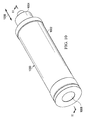
- linear electric motor 1000 comprises base 1002 and member 1004.
- Member 1004 is moveable in the direction of arrow 1006.
- the movement of member 1004 occurs through motor 1008 located inside of base 1002.
- motor 1008 is configured to move member 1004 in the direction of arrow 1006 without needing gears, linkages, or other moving parts that may increase maintenance needs for linear electric motor 1000.
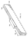
- FIG. 11 an illustration of a cross-sectional view of a linear electric motor is depicted in accordance with an illustrative embodiment.
- linear electric motor 1000 is shown in a cross-sectional view taken along lines 11-11 in Figure 10 .
- member 1004 may take the form of a hollow tube that may move in the direction of arrow 1006. This movement may occur through an interaction between magnet system 1100 and coil system 1102 in motor 1008.
- coil system 1102 uses electrical energy to generate magnetic fields. These magnetic fields interact with the magnetic fields in magnet system 1100 to cause linear movement in the direction of arrow 1006.
- member 1004 may extend or retract with respect to base 1002 of linear electric motor 1000.
- coil system 1102 is associated with housing 1108 for base 1002.
- Magnet system 1100 is moveable along pole 1110. Movement of magnet system 1100 along pole 1110 causes movement of member 1004.
- the movement of member 1004 occurs using forces caused by electromagnetic fields. These forces result in linear movement in the direction of arrow 1006 by attaching member 1004 to a structure, such as a sleeve, the sleeve may be moved without needing additional components such as gears, linkages, or other similar components.
- base 1002 may also include position detector 1104 and load cell 1106.
- position detector 1104 in load cell 1106 is shown as part of linear electric motor 1000. In other illustrative examples, these components may be external and separate from linear electric motor 1000.
- linear electric motor 1000 may be implemented using any currently available electric motor that converts electrical energy into mechanical energy in which the mechanical energy is directed linearly.
- linear electric motors may be used that may use stators, opposing coils, or other components in place of or in addition to magnet system 1100.
- linear electric motor 1200 comprises base 1202 and member 1204.
- Member 1204 may be connected to a sleeve.
- Base 1202 may be connected to another structure in an engine.
- linear electric motor 1200 may include coils, stators, and magnets that use electro-magnetic forces to move member 1204.
- linear electric motor 1300 comprises base 1302 and member 1304. Movement of member 1304 may be caused through the conversion of electrical energy into mechanical energy in which electro-magnetic forces are used to cause the movement. Member 1304 may be moved in the direction of arrow 1306.
- base 1302 may be connected to a structure on an engine, while member 1304 may be connected to a sleeve.
- Figures 6-9 illustrate the use of three linear electric motors with each sleeve, other numbers of linear electric motors may be used.
- a sleeve may be moved using two linear electric motors, four linear electric motors, or some other number of linear electric motors depending on the implementation.
- Two sleeves, sleeve 400 and sleeve 402 are show for engine 110 in Figure 4 and Figure 5 . In other illustrative examples, only a single sleeve may be present. In still other examples, more than two sleeves may be present for engine 110.
- Figure 1 and Figures 4 -13 may be combined with components in Figure 2 and Figure 3 , used with components in Figure 2 and Figure 3 , or a combination of the two. Additionally, some of the components in Figures 1 and Figures 4-13 may be illustrative examples of how components shown in block form in Figure 2 and Figure 3 can be implemented as physical structures.
- FIG 14 an illustration of a flowchart of a process for operating a thrust reverser system for an aircraft is depicted in accordance with an illustrative embodiment.
- the process illustrated in Figure 14 may be implemented using thrust reverser system 200 in Figure 2 or thrust reverser system 300 in Figure 3 .
- the process begins by receiving a request to move a sleeve to a position that causes a direction of thrust generated by an engine for an aircraft to change from an aft direction to a forward direction (operation 1400).
- the process moves the sleeve on the engine in the thrust reverser system from a first position to a second position using a number of linear electric motors connected to the sleeve (operation 1402) with the process terminating thereafter.
- the second position is one that causes thrust generated by the engine for the aircraft to be directed in a substantially opposite direction.
- the direction is changed from an aft direction to a forward direction in this example.
- the same process may be performed to move the sleeve from the second position back to the first position.
- the thrust is directed in an aft direction.
- FIG 15 an illustration of a flowchart of a process for moving a sleeve in a thrust reverser system is depicted in accordance with an illustrative embodiment. This process may be implemented in thrust reverser system 200 in Figure 2 and thrust reverser system 300 in Figure 3 .
- the process begins by sending commands to a number of linear electric motors to cause movement of a sleeve toward a desired position (operation 1500).
- the process receives data about the position of the sleeve and a number of loads on the number of linear electric motors (operation 1502).
- the position information about the sleeve may be calculated from the position of the linear electric motors. In other illustrative examples, the position information may be obtained from a sensor associated with the sleeve.
- the information about the number of loads is received from the number of linear electric motors in this illustrative example.
- FIG 16 an illustration of a flowchart of a process for operating linear electric motors to move a sleeve is depicted in accordance with an illustrative embodiment. This process may be implemented in thrust reverser system 200 in Figure 2 and thrust reverser system 300 in Figure 3 .
- the process begins by determining whether the linear electric motors are functioning as desired (operation 1600).
- a controller such as controller 302 in Figure 3 , may make the determination in operation 1600. This determination may be made based on data received from the linear electric motors or a lack of data received from the linear electric motors. For example, data may indicate whether a linear electric motor is moving or responding as expected to commands sent to the linear electric motor. Lack of data may indicate that the linear electric motor is not functioning. Undesired operation may be reported such that maintenance may be performed on a linear electric motor that is identified as not operating as desired.
- the process terminates. Otherwise, the process places the linear electric motor that is not functioning as desired into a float mode (operation 1602). In operation 1602, the linear electric motor is controlled such that the member connected to the sleeve moves freely. In other words, the linear electric motor does not generate any force to move the member or maintain the member in a particular position.
- the process then controls operation of a group of remaining linear electric motors in the linear electric motors to move the sleeve between the first position and the second position taking into account load changes caused by the linear electric motor that is not operating as desired (operation 1604), with the process terminating thereafter.
- a "group" when used with reference to items means one or more items.
- a group of remaining linear electric motors is one or more remaining linear electric motors.
- these load changes may be taken into account such that the load on the group of linear electric motors is below a selected load such as selected load 240 in Figure 2 .
- each block in the flowcharts or block diagrams may represent a module, segment, function, and/or a portion of an operation or step.
- one or more of the blocks may be implemented as program code, in hardware, or a combination of the program code and hardware.
- the hardware may, for example, take the form of integrated circuits that are manufactured or configured to perform one or more operations in the flowcharts or block diagrams.
- the function or functions noted in the blocks may occur out of the order noted in the figures.
- two blocks shown in succession may be executed substantially concurrently, or the blocks may sometimes be performed in the reverse order, depending upon the functionality involved.
- other blocks may be added in addition to the illustrated blocks in a flowchart or block diagram.
- the illustrative embodiments provide a method and apparatus for moving a sleeve in a thrust reverser system.
- linear electric motors are used to move the sleeve.
- These linear electric motors may be directly connected to the sleeve.
- linkages, gears, or other moving components may be absent in the connection. This type of connection may reduce the amount of maintenance needed for a thrust reverser system.
- the movement of a sleeve may occur more quickly and precisely as compared to hydraulics systems used to move a sleeve.
- the illustrative examples may control operation of the linear electric motors such that the loads on the linear electric motors remain below a selected load.
- the selected load may be one that may result in increased maintenance for the linear electric motors.
- the selected load may be one in which the linear electric motors are unable to support during movement of the sleeve. As a result, smaller linear electric motors may be used, which may result in less weight and a lower cost.
Landscapes
- Engineering & Computer Science (AREA)
- Mechanical Engineering (AREA)
- General Engineering & Computer Science (AREA)
- Chemical & Material Sciences (AREA)
- Combustion & Propulsion (AREA)
- Linear Motors (AREA)
- Control Of Linear Motors (AREA)
Applications Claiming Priority (1)
| Application Number | Priority Date | Filing Date | Title |
|---|---|---|---|
| US13/480,299 US9482180B2 (en) | 2012-05-24 | 2012-05-24 | Thrust reverser system |
Publications (3)
| Publication Number | Publication Date |
|---|---|
| EP2667005A2 true EP2667005A2 (fr) | 2013-11-27 |
| EP2667005A3 EP2667005A3 (fr) | 2015-07-15 |
| EP2667005B1 EP2667005B1 (fr) | 2019-08-07 |
Family
ID=48325381
Family Applications (1)
| Application Number | Title | Priority Date | Filing Date |
|---|---|---|---|
| EP13165423.8A Active EP2667005B1 (fr) | 2012-05-24 | 2013-04-25 | Système inverseur de poussée |
Country Status (5)
| Country | Link |
|---|---|
| US (1) | US9482180B2 (fr) |
| EP (1) | EP2667005B1 (fr) |
| CN (1) | CN103423029B (fr) |
| BR (1) | BR102013012747B1 (fr) |
| CA (1) | CA2807905C (fr) |
Families Citing this family (6)
| Publication number | Priority date | Publication date | Assignee | Title |
|---|---|---|---|---|
| US20150090810A1 (en) * | 2013-02-11 | 2015-04-02 | Spirit Aerosystems, Inc. | Thrust reverser hydraulic actuation system with servo synchronization |
| US20160290283A1 (en) * | 2015-03-30 | 2016-10-06 | Honeywell International Inc. | Fluid-powered thrust reverser actuation system with electromechanical speed control |
| EP3193003A1 (fr) * | 2016-01-15 | 2017-07-19 | Goodrich Actuation Systems Ltd. | Architecture de système de commande d'inverseur de poussée |
| US10794327B2 (en) * | 2018-03-21 | 2020-10-06 | Honeywell International Inc. | Systems and methods for thrust reverser with temperature and fluid management |
| EP4253747B1 (fr) | 2022-03-31 | 2026-04-29 | Goodrich Actuation Systems SAS | Système de verrouillage pour un inverseur de poussée |
| FR3149296A1 (fr) * | 2023-06-05 | 2024-12-06 | Safran Electronics & Defense | Système d'actionnement et de freinage d'un système avionique |
Family Cites Families (23)
| Publication number | Priority date | Publication date | Assignee | Title |
|---|---|---|---|---|
| US3829020A (en) | 1973-06-13 | 1974-08-13 | Boeing Co | Translating sleeve variable area nozzle and thrust reverser |
| US4852805A (en) | 1983-12-30 | 1989-08-01 | The Boeing Company | Hybrid thrust reverser cascade basket and method |
| GB8920013D0 (en) * | 1989-09-05 | 1989-10-18 | Kelly H P G | Improvements in or relating to the control of linear motors |
| FR2755730B1 (fr) * | 1996-11-14 | 1999-01-08 | Hispano Suiza Sa | Systeme de commande electrique pour inverseur de poussee de turboreacteur |
| US6519929B2 (en) * | 2001-04-30 | 2003-02-18 | Honeywell International, Inc. | System and method for controlling the deployment of jet engine thrust reversers |
| GB0117904D0 (en) * | 2001-07-23 | 2001-09-12 | Lucas Industries Ltd | Motor control system |
| FR2830051B1 (fr) | 2001-09-27 | 2003-11-07 | Hurel Hispano Le Havre | Systeme de verrouillage sur un inverseur de poussee a grilles |
| US6655125B2 (en) * | 2001-12-05 | 2003-12-02 | Honeywell International Inc. | System architecture for electromechanical thrust reverser actuation systems |
| US6791215B2 (en) | 2002-06-05 | 2004-09-14 | Board Of Regents The University Of Texas System | Fault tolerant linear actuator |
| FR2846375B1 (fr) * | 2002-10-25 | 2006-06-30 | Hispano Suiza Sa | Inverseur de poussee electromacanique pour turboreacteur a asservissement du deplacement des portes |
| GB0327457D0 (en) * | 2003-11-26 | 2003-12-31 | Goodrich Actuation Systems Ltd | Linear actuator |
| US7834494B2 (en) * | 2004-06-04 | 2010-11-16 | The Boeing Company | Fault-tolerant electromechanical actuator having a torque sensing control system |
| US7378765B2 (en) * | 2004-08-09 | 2008-05-27 | Oriental Motor Co., Ltd. | Cylinder-type linear motor and moving part thereof |
| EP1793477B1 (fr) | 2005-12-02 | 2012-02-15 | The Boeing Company | Actionneur électromagnétique tolérant aux défauts avec système de détection et de contrôle de couple |
| GB0705301D0 (en) | 2007-03-20 | 2007-04-25 | Goodrich Actuation Systems Ltd | Actuator arrangement |
| GB0706270D0 (en) | 2007-03-30 | 2007-05-09 | Goodrich Actuation Systems Ltd | Actuator arrangement |
| EP2479414B1 (fr) * | 2007-08-08 | 2015-06-10 | Rohr, Inc. | Tuyère de soufflante à surface variable avec flux de dérivation |
| FR2920204B1 (fr) * | 2007-08-20 | 2009-10-30 | Aircelle Sa | Procede et systeme de commande d'au moins un actionneur de capots d'un inverseur de poussee pour turboreacteur |
| FR2922058B1 (fr) | 2007-10-04 | 2009-12-04 | Aircelle Sa | Actionneur lineaire telescopique pour deplacer un premier et un second elements relativement a un element fixe |
| FR2932226B1 (fr) * | 2008-06-06 | 2013-08-23 | Aircelle Sa | Procede de synchronisation des actionneurs d'un capot mobile d'inverseur de poussee |
| FR2944563B1 (fr) * | 2009-04-16 | 2011-04-22 | Aircelle Sa | Dispositif d'inversion de poussee |
| JP2012090467A (ja) * | 2010-10-21 | 2012-05-10 | Seiko Epson Corp | リニアモーター |
| US9303590B2 (en) * | 2012-05-22 | 2016-04-05 | Spirit Aerosystems, Inc. | Variable area fan nozzle actuation system |
-
2012
- 2012-05-24 US US13/480,299 patent/US9482180B2/en not_active Expired - Fee Related
-
2013
- 2013-02-26 CA CA2807905A patent/CA2807905C/fr active Active
- 2013-04-25 EP EP13165423.8A patent/EP2667005B1/fr active Active
- 2013-05-23 CN CN201310193712.5A patent/CN103423029B/zh not_active Expired - Fee Related
- 2013-05-23 BR BR102013012747-7A patent/BR102013012747B1/pt not_active IP Right Cessation
Non-Patent Citations (1)
| Title |
|---|
| None |
Also Published As
| Publication number | Publication date |
|---|---|
| EP2667005B1 (fr) | 2019-08-07 |
| CN103423029A (zh) | 2013-12-04 |
| BR102013012747A2 (pt) | 2015-06-09 |
| CA2807905C (fr) | 2017-05-16 |
| CN103423029B (zh) | 2017-07-25 |
| EP2667005A3 (fr) | 2015-07-15 |
| BR102013012747B1 (pt) | 2022-03-22 |
| CA2807905A1 (fr) | 2013-11-24 |
| US20130313337A1 (en) | 2013-11-28 |
| US9482180B2 (en) | 2016-11-01 |
Similar Documents
| Publication | Publication Date | Title |
|---|---|---|
| EP2667005B1 (fr) | Système inverseur de poussée | |
| US11053889B2 (en) | Thrust reverser flow limiting valve | |
| EP3051112B1 (fr) | Inverseur de poussée à cascade déployable en translation et à porte de blocage cachée | |
| US10450061B2 (en) | Servo actuators | |
| CN101784964B (zh) | 控制一涡轮喷气发动机的推力反向器整流罩的至少一致动器的方法与系统 | |
| EP2439139A2 (fr) | Actionneur hydraulique d'aeronef | |
| US20160222889A1 (en) | Distributed electrical architecture | |
| US20130336816A1 (en) | Aircraft actuator hydraulic system | |
| EP2865851A1 (fr) | Système d'actionnement à inverseur de poussée hybride entraîné par un moteur hydraulique rotatif avec amortissement de fin de course | |
| US8907595B2 (en) | Aircraft engine nacelle comprising a mobile cowl moved by electric motors | |
| US11255294B2 (en) | Thrust reverser velocity control valve | |
| US20110296812A1 (en) | Thrust reverser actuation system architecture | |
| CN101025128A (zh) | 一种轴对称矢量喷管a9作动应急复位液压系统 | |
| Behbahani et al. | Control strategy for electro-mechanical actuators versus hydraulic actuation systems for aerospace applications | |
| CN101784782B (zh) | 控制一涡轮喷气发动机的推力反向器整流罩的至少一致动器的系统 | |
| EP3018328B1 (fr) | Liaison de manchon pour inverseur de poussée | |
| CN109204848B (zh) | 伸缩式辅助进气装置 | |
| EP4390177B1 (fr) | Dispositif d'amortissement | |
| US20190161172A1 (en) | Mode valve assembly |
Legal Events
| Date | Code | Title | Description |
|---|---|---|---|
| PUAI | Public reference made under article 153(3) epc to a published international application that has entered the european phase |
Free format text: ORIGINAL CODE: 0009012 |
|
| AK | Designated contracting states |
Kind code of ref document: A2 Designated state(s): AL AT BE BG CH CY CZ DE DK EE ES FI FR GB GR HR HU IE IS IT LI LT LU LV MC MK MT NL NO PL PT RO RS SE SI SK SM TR |
|
| AX | Request for extension of the european patent |
Extension state: BA ME |
|
| PUAL | Search report despatched |
Free format text: ORIGINAL CODE: 0009013 |
|
| AK | Designated contracting states |
Kind code of ref document: A3 Designated state(s): AL AT BE BG CH CY CZ DE DK EE ES FI FR GB GR HR HU IE IS IT LI LT LU LV MC MK MT NL NO PL PT RO RS SE SI SK SM TR |
|
| AX | Request for extension of the european patent |
Extension state: BA ME |
|
| RIC1 | Information provided on ipc code assigned before grant |
Ipc: F01D 17/24 20060101ALI20150609BHEP Ipc: F02K 1/72 20060101AFI20150609BHEP Ipc: F02K 1/76 20060101ALI20150609BHEP |
|
| 17P | Request for examination filed |
Effective date: 20151228 |
|
| RBV | Designated contracting states (corrected) |
Designated state(s): AL AT BE BG CH CY CZ DE DK EE ES FI FR GB GR HR HU IE IS IT LI LT LU LV MC MK MT NL NO PL PT RO RS SE SI SK SM TR |
|
| STAA | Information on the status of an ep patent application or granted ep patent |
Free format text: STATUS: EXAMINATION IS IN PROGRESS |
|
| 17Q | First examination report despatched |
Effective date: 20171030 |
|
| GRAP | Despatch of communication of intention to grant a patent |
Free format text: ORIGINAL CODE: EPIDOSNIGR1 |
|
| STAA | Information on the status of an ep patent application or granted ep patent |
Free format text: STATUS: GRANT OF PATENT IS INTENDED |
|
| INTG | Intention to grant announced |
Effective date: 20190215 |
|
| GRAS | Grant fee paid |
Free format text: ORIGINAL CODE: EPIDOSNIGR3 |
|
| GRAA | (expected) grant |
Free format text: ORIGINAL CODE: 0009210 |
|
| STAA | Information on the status of an ep patent application or granted ep patent |
Free format text: STATUS: THE PATENT HAS BEEN GRANTED |
|
| AK | Designated contracting states |
Kind code of ref document: B1 Designated state(s): AL AT BE BG CH CY CZ DE DK EE ES FI FR GB GR HR HU IE IS IT LI LT LU LV MC MK MT NL NO PL PT RO RS SE SI SK SM TR |
|
| REG | Reference to a national code |
Ref country code: GB Ref legal event code: FG4D |
|
| REG | Reference to a national code |
Ref country code: CH Ref legal event code: EP Ref country code: AT Ref legal event code: REF Ref document number: 1164256 Country of ref document: AT Kind code of ref document: T Effective date: 20190815 |
|
| REG | Reference to a national code |
Ref country code: DE Ref legal event code: R096 Ref document number: 602013058681 Country of ref document: DE |
|
| REG | Reference to a national code |
Ref country code: IE Ref legal event code: FG4D |
|
| REG | Reference to a national code |
Ref country code: NL Ref legal event code: MP Effective date: 20190807 |
|
| REG | Reference to a national code |
Ref country code: LT Ref legal event code: MG4D |
|
| PG25 | Lapsed in a contracting state [announced via postgrant information from national office to epo] |
Ref country code: NL Free format text: LAPSE BECAUSE OF FAILURE TO SUBMIT A TRANSLATION OF THE DESCRIPTION OR TO PAY THE FEE WITHIN THE PRESCRIBED TIME-LIMIT Effective date: 20190807 Ref country code: BG Free format text: LAPSE BECAUSE OF FAILURE TO SUBMIT A TRANSLATION OF THE DESCRIPTION OR TO PAY THE FEE WITHIN THE PRESCRIBED TIME-LIMIT Effective date: 20191107 Ref country code: HR Free format text: LAPSE BECAUSE OF FAILURE TO SUBMIT A TRANSLATION OF THE DESCRIPTION OR TO PAY THE FEE WITHIN THE PRESCRIBED TIME-LIMIT Effective date: 20190807 Ref country code: LT Free format text: LAPSE BECAUSE OF FAILURE TO SUBMIT A TRANSLATION OF THE DESCRIPTION OR TO PAY THE FEE WITHIN THE PRESCRIBED TIME-LIMIT Effective date: 20190807 Ref country code: NO Free format text: LAPSE BECAUSE OF FAILURE TO SUBMIT A TRANSLATION OF THE DESCRIPTION OR TO PAY THE FEE WITHIN THE PRESCRIBED TIME-LIMIT Effective date: 20191107 Ref country code: PT Free format text: LAPSE BECAUSE OF FAILURE TO SUBMIT A TRANSLATION OF THE DESCRIPTION OR TO PAY THE FEE WITHIN THE PRESCRIBED TIME-LIMIT Effective date: 20191209 Ref country code: FI Free format text: LAPSE BECAUSE OF FAILURE TO SUBMIT A TRANSLATION OF THE DESCRIPTION OR TO PAY THE FEE WITHIN THE PRESCRIBED TIME-LIMIT Effective date: 20190807 Ref country code: SE Free format text: LAPSE BECAUSE OF FAILURE TO SUBMIT A TRANSLATION OF THE DESCRIPTION OR TO PAY THE FEE WITHIN THE PRESCRIBED TIME-LIMIT Effective date: 20190807 |
|
| REG | Reference to a national code |
Ref country code: AT Ref legal event code: MK05 Ref document number: 1164256 Country of ref document: AT Kind code of ref document: T Effective date: 20190807 |
|
| PG25 | Lapsed in a contracting state [announced via postgrant information from national office to epo] |
Ref country code: LV Free format text: LAPSE BECAUSE OF FAILURE TO SUBMIT A TRANSLATION OF THE DESCRIPTION OR TO PAY THE FEE WITHIN THE PRESCRIBED TIME-LIMIT Effective date: 20190807 Ref country code: GR Free format text: LAPSE BECAUSE OF FAILURE TO SUBMIT A TRANSLATION OF THE DESCRIPTION OR TO PAY THE FEE WITHIN THE PRESCRIBED TIME-LIMIT Effective date: 20191108 Ref country code: AL Free format text: LAPSE BECAUSE OF FAILURE TO SUBMIT A TRANSLATION OF THE DESCRIPTION OR TO PAY THE FEE WITHIN THE PRESCRIBED TIME-LIMIT Effective date: 20190807 Ref country code: IS Free format text: LAPSE BECAUSE OF FAILURE TO SUBMIT A TRANSLATION OF THE DESCRIPTION OR TO PAY THE FEE WITHIN THE PRESCRIBED TIME-LIMIT Effective date: 20191207 Ref country code: RS Free format text: LAPSE BECAUSE OF FAILURE TO SUBMIT A TRANSLATION OF THE DESCRIPTION OR TO PAY THE FEE WITHIN THE PRESCRIBED TIME-LIMIT Effective date: 20190807 Ref country code: ES Free format text: LAPSE BECAUSE OF FAILURE TO SUBMIT A TRANSLATION OF THE DESCRIPTION OR TO PAY THE FEE WITHIN THE PRESCRIBED TIME-LIMIT Effective date: 20190807 |
|
| PG25 | Lapsed in a contracting state [announced via postgrant information from national office to epo] |
Ref country code: TR Free format text: LAPSE BECAUSE OF FAILURE TO SUBMIT A TRANSLATION OF THE DESCRIPTION OR TO PAY THE FEE WITHIN THE PRESCRIBED TIME-LIMIT Effective date: 20190807 |
|
| PG25 | Lapsed in a contracting state [announced via postgrant information from national office to epo] |
Ref country code: AT Free format text: LAPSE BECAUSE OF FAILURE TO SUBMIT A TRANSLATION OF THE DESCRIPTION OR TO PAY THE FEE WITHIN THE PRESCRIBED TIME-LIMIT Effective date: 20190807 Ref country code: EE Free format text: LAPSE BECAUSE OF FAILURE TO SUBMIT A TRANSLATION OF THE DESCRIPTION OR TO PAY THE FEE WITHIN THE PRESCRIBED TIME-LIMIT Effective date: 20190807 Ref country code: DK Free format text: LAPSE BECAUSE OF FAILURE TO SUBMIT A TRANSLATION OF THE DESCRIPTION OR TO PAY THE FEE WITHIN THE PRESCRIBED TIME-LIMIT Effective date: 20190807 Ref country code: RO Free format text: LAPSE BECAUSE OF FAILURE TO SUBMIT A TRANSLATION OF THE DESCRIPTION OR TO PAY THE FEE WITHIN THE PRESCRIBED TIME-LIMIT Effective date: 20190807 Ref country code: IT Free format text: LAPSE BECAUSE OF FAILURE TO SUBMIT A TRANSLATION OF THE DESCRIPTION OR TO PAY THE FEE WITHIN THE PRESCRIBED TIME-LIMIT Effective date: 20190807 Ref country code: PL Free format text: LAPSE BECAUSE OF FAILURE TO SUBMIT A TRANSLATION OF THE DESCRIPTION OR TO PAY THE FEE WITHIN THE PRESCRIBED TIME-LIMIT Effective date: 20190807 |
|
| PG25 | Lapsed in a contracting state [announced via postgrant information from national office to epo] |
Ref country code: CZ Free format text: LAPSE BECAUSE OF FAILURE TO SUBMIT A TRANSLATION OF THE DESCRIPTION OR TO PAY THE FEE WITHIN THE PRESCRIBED TIME-LIMIT Effective date: 20190807 Ref country code: SK Free format text: LAPSE BECAUSE OF FAILURE TO SUBMIT A TRANSLATION OF THE DESCRIPTION OR TO PAY THE FEE WITHIN THE PRESCRIBED TIME-LIMIT Effective date: 20190807 Ref country code: IS Free format text: LAPSE BECAUSE OF FAILURE TO SUBMIT A TRANSLATION OF THE DESCRIPTION OR TO PAY THE FEE WITHIN THE PRESCRIBED TIME-LIMIT Effective date: 20200224 Ref country code: SM Free format text: LAPSE BECAUSE OF FAILURE TO SUBMIT A TRANSLATION OF THE DESCRIPTION OR TO PAY THE FEE WITHIN THE PRESCRIBED TIME-LIMIT Effective date: 20190807 |
|
| REG | Reference to a national code |
Ref country code: DE Ref legal event code: R097 Ref document number: 602013058681 Country of ref document: DE |
|
| PLBE | No opposition filed within time limit |
Free format text: ORIGINAL CODE: 0009261 |
|
| STAA | Information on the status of an ep patent application or granted ep patent |
Free format text: STATUS: NO OPPOSITION FILED WITHIN TIME LIMIT |
|
| PG2D | Information on lapse in contracting state deleted |
Ref country code: IS |
|
| 26N | No opposition filed |
Effective date: 20200603 |
|
| PG25 | Lapsed in a contracting state [announced via postgrant information from national office to epo] |
Ref country code: SI Free format text: LAPSE BECAUSE OF FAILURE TO SUBMIT A TRANSLATION OF THE DESCRIPTION OR TO PAY THE FEE WITHIN THE PRESCRIBED TIME-LIMIT Effective date: 20190807 |
|
| PG25 | Lapsed in a contracting state [announced via postgrant information from national office to epo] |
Ref country code: MC Free format text: LAPSE BECAUSE OF FAILURE TO SUBMIT A TRANSLATION OF THE DESCRIPTION OR TO PAY THE FEE WITHIN THE PRESCRIBED TIME-LIMIT Effective date: 20190807 |
|
| REG | Reference to a national code |
Ref country code: CH Ref legal event code: PL |
|
| PG25 | Lapsed in a contracting state [announced via postgrant information from national office to epo] |
Ref country code: LI Free format text: LAPSE BECAUSE OF NON-PAYMENT OF DUE FEES Effective date: 20200430 Ref country code: LU Free format text: LAPSE BECAUSE OF NON-PAYMENT OF DUE FEES Effective date: 20200425 Ref country code: CH Free format text: LAPSE BECAUSE OF NON-PAYMENT OF DUE FEES Effective date: 20200430 |
|
| REG | Reference to a national code |
Ref country code: BE Ref legal event code: MM Effective date: 20200430 |
|
| PG25 | Lapsed in a contracting state [announced via postgrant information from national office to epo] |
Ref country code: BE Free format text: LAPSE BECAUSE OF NON-PAYMENT OF DUE FEES Effective date: 20200430 |
|
| PG25 | Lapsed in a contracting state [announced via postgrant information from national office to epo] |
Ref country code: IE Free format text: LAPSE BECAUSE OF NON-PAYMENT OF DUE FEES Effective date: 20200425 |
|
| PG25 | Lapsed in a contracting state [announced via postgrant information from national office to epo] |
Ref country code: MT Free format text: LAPSE BECAUSE OF FAILURE TO SUBMIT A TRANSLATION OF THE DESCRIPTION OR TO PAY THE FEE WITHIN THE PRESCRIBED TIME-LIMIT Effective date: 20190807 Ref country code: CY Free format text: LAPSE BECAUSE OF FAILURE TO SUBMIT A TRANSLATION OF THE DESCRIPTION OR TO PAY THE FEE WITHIN THE PRESCRIBED TIME-LIMIT Effective date: 20190807 |
|
| PG25 | Lapsed in a contracting state [announced via postgrant information from national office to epo] |
Ref country code: MK Free format text: LAPSE BECAUSE OF FAILURE TO SUBMIT A TRANSLATION OF THE DESCRIPTION OR TO PAY THE FEE WITHIN THE PRESCRIBED TIME-LIMIT Effective date: 20190807 |
|
| P01 | Opt-out of the competence of the unified patent court (upc) registered |
Effective date: 20230516 |
|
| PGFP | Annual fee paid to national office [announced via postgrant information from national office to epo] |
Ref country code: FR Payment date: 20230425 Year of fee payment: 11 Ref country code: DE Payment date: 20230427 Year of fee payment: 11 |
|
| PGFP | Annual fee paid to national office [announced via postgrant information from national office to epo] |
Ref country code: GB Payment date: 20230427 Year of fee payment: 11 |
|
| REG | Reference to a national code |
Ref country code: DE Ref legal event code: R119 Ref document number: 602013058681 Country of ref document: DE |
|
| GBPC | Gb: european patent ceased through non-payment of renewal fee |
Effective date: 20240425 |
|
| PG25 | Lapsed in a contracting state [announced via postgrant information from national office to epo] |
Ref country code: DE Free format text: LAPSE BECAUSE OF NON-PAYMENT OF DUE FEES Effective date: 20241105 |
|
| PG25 | Lapsed in a contracting state [announced via postgrant information from national office to epo] |
Ref country code: GB Free format text: LAPSE BECAUSE OF NON-PAYMENT OF DUE FEES Effective date: 20240425 |
|
| PG25 | Lapsed in a contracting state [announced via postgrant information from national office to epo] |
Ref country code: FR Free format text: LAPSE BECAUSE OF NON-PAYMENT OF DUE FEES Effective date: 20240430 |
|
| PG25 | Lapsed in a contracting state [announced via postgrant information from national office to epo] |
Ref country code: GB Free format text: LAPSE BECAUSE OF NON-PAYMENT OF DUE FEES Effective date: 20240425 Ref country code: FR Free format text: LAPSE BECAUSE OF NON-PAYMENT OF DUE FEES Effective date: 20240430 Ref country code: DE Free format text: LAPSE BECAUSE OF NON-PAYMENT OF DUE FEES Effective date: 20241105 |