EP2667355B1 - Objekterkennungssystem und Verfahren unter Verwendung einer Kamera und eines vielzonigen Temperatursensors - Google Patents
Objekterkennungssystem und Verfahren unter Verwendung einer Kamera und eines vielzonigen Temperatursensors Download PDFInfo
- Publication number
- EP2667355B1 EP2667355B1 EP13168576.0A EP13168576A EP2667355B1 EP 2667355 B1 EP2667355 B1 EP 2667355B1 EP 13168576 A EP13168576 A EP 13168576A EP 2667355 B1 EP2667355 B1 EP 2667355B1
- Authority
- EP
- European Patent Office
- Prior art keywords
- temperature
- intensity
- hue
- data
- saturation
- Prior art date
- Legal status (The legal status is an assumption and is not a legal conclusion. Google has not performed a legal analysis and makes no representation as to the accuracy of the status listed.)
- Active
Links
Images


Classifications
-
- G—PHYSICS
- G06—COMPUTING OR CALCULATING; COUNTING
- G06T—IMAGE DATA PROCESSING OR GENERATION, IN GENERAL
- G06T7/00—Image analysis
- G06T7/10—Segmentation; Edge detection
- G06T7/174—Segmentation; Edge detection involving the use of two or more images
-
- G—PHYSICS
- G06—COMPUTING OR CALCULATING; COUNTING
- G06T—IMAGE DATA PROCESSING OR GENERATION, IN GENERAL
- G06T7/00—Image analysis
- G06T7/10—Segmentation; Edge detection
- G06T7/11—Region-based segmentation
-
- G—PHYSICS
- G06—COMPUTING OR CALCULATING; COUNTING
- G06T—IMAGE DATA PROCESSING OR GENERATION, IN GENERAL
- G06T2207/00—Indexing scheme for image analysis or image enhancement
- G06T2207/10—Image acquisition modality
- G06T2207/10048—Infrared image
-
- G—PHYSICS
- G06—COMPUTING OR CALCULATING; COUNTING
- G06T—IMAGE DATA PROCESSING OR GENERATION, IN GENERAL
- G06T2207/00—Indexing scheme for image analysis or image enhancement
- G06T2207/30—Subject of image; Context of image processing
- G06T2207/30248—Vehicle exterior or interior
- G06T2207/30252—Vehicle exterior; Vicinity of vehicle
- G06T2207/30261—Obstacle
Definitions
- This disclosure generally relates to object detection for vehicle collision avoidance, and more particularly relates to a way to combine or fuse information from a visible light camera and a multiple zone temperature sensor so a vehicle operator can more readily detect an object proximate to the vehicle.
- Vehicle operator warning systems that alert vehicle operator of objects that may be a collision hazard are known. These systems typically provide the operator an audio and/or visual warning of an impending or potential collision, preferably with sufficient reaction time for the vehicle operator to respond to the warning and make appropriate countermeasures to prevent the collision.
- Rear view camera systems that allow the operator to view areas behind the vehicle are also known. These systems help the operator to detect objects blocked from view by the rear portion of the vehicle, or are located in areas commonly known as blind spots. However, even if the vehicle is equipped with a rear view camera system, the operator may not be able to discern potential obstacles displayed by the system. For example, the wide range of ambient lighting conditions experienced by the vehicle, combined with the wide range of reflectivity values of potential objects can make object identification and or classification difficult.
- Thermal imaging cameras or infrared cameras have also been used in automotive applications for object detection. However, such cameras have undesirably high cost. Also, some operators have difficulty interpreting what is being indicated in the thermal image as they often resemble an antiquated black and white television display.
- US Patent Application Publication US 20100013615 discloses a method of classifying objects in an image by objects density and colour.
- US Patent Application Publication US2009050806 discloses a combined visible light and IR combined image camera.
- US Patent US 5001558 describes a night vision system with colour video camera.
- European Patent EP 2083410 describes an abject detection system including a thermal imaging detector
- a controller (30) for a system (10) configured to provide a notification to an operator (20) of a vehicle (12) that an object (14) is proximate to the vehicle (12), said system (10) comprising a visible light camera (16) mounted on the vehicle (12) effective to have a camera field of view (22), and configured to output image data (26) indicative of visible light color and visible light intensity detected by pixels in the camera (16), and a multiple zone temperature sensor (18) mounted on the vehicle (12) effective to have a sensor field of view (24) similar to the camera field of view (22), and configured to output temperature data (28) indicative of a zone temperature for each of the multiple zones, said controller (30) configured to
- system (10) said system (10) further comprising a warning indicator (36) coupled to the controller (30) effective to generate a warning signal (38) when the detected object (62) is detected.
- a warning indicator (36) coupled to the controller (30) effective to generate a warning signal (38) when the detected object (62) is detected.
- a method to provide a notification to an operator of a vehicle that an object is proximate to the vehicle is provided.
- the notification is based on image data from a visible light camera mounted on the vehicle effective to have a camera field of view, and a multiple zone temperature sensor mounted on the vehicle effective to have a sensor field of view similar to the camera field of view.
- the method includes the steps of :
- said method (300) further comprises generating a warning signal (38) when the detected object (62) is detected.
- said method (300) wherein said method (300) further comprises increasing the number of hue data cells designated as the hue object (50) based on one or more of a hue object (50) shape and a hue object (50) size.
- said method (300) further comprises increasing the number of saturation data cells designated as the saturation object (50) based on one or more of a saturation object (50) shape and a saturation object (50) size.
- said method (300) further comprises increasing the number of intensity data cells designated as the intensity object (14) based on one or more of an intensity object (14) shape and an intensity object (14) size.
- said method (300) further comprises increasing the number of temperature data (28) cells designated as the temperature object (60) based on one or more of a temperature object (60) shape and a temperature object (60) size.
- the method (300), wherein the step (305) of designating a detected object (62) based on an object (14) map includes determining that the detected object (62) persists for a time longer than a persistence time threshold
- the method (300), wherein the step (305) of designating as a detected object (62) an area on an object (14) map includes determining that the detected object (62) moves at a speed less than a speed threshold.
- determining a temperature map (56) includes:
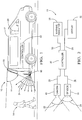
- Fig. 1 illustrates a non-limiting example of a system 10 generally configured to provide an operator 20 of a vehicle 12 a notification that an object 14 is proximate to the vehicle 12.
- the object 14 is a child that is located behind the vehicle 12.
- the system 10 is also useful to detect an adult, an animal, other vehicle, or any obstruction that the vehicle 12 may collide with.
- the system 10 includes a visible light camera 16 and a multiple zone temperature sensor 18.
- the camera 16 is mounted on the vehicle 12 in order to have a camera field of view 22 useful to detect objects that may not be readily seen by the operator 20.
- the camera field of view 22 is directed behind the vehicle 12.
- the system 10 could be configured to detect an object beside or in front of the vehicle 12.
- the sensor 18 is mounted on the vehicle 12 in order to have a sensor field of view 24 that is also useful to detect objects that may not be readily seen by the operator 20 because, for example, the object 14 is behind the vehicle 12.
- the camera 16 and the sensor 18 are illustrated as being substantially separated only for the purpose of illustration. It is recognized that the camera 16 and the sensor 18 are preferably co-located so that both have essentially the same field of view. If the camera 16 and sensor 18 are separated, known image processing techniques may be used to transform the apparent fields of view to substantially correspond. As used herein, having the sensor field of view 24 similar to the camera field of view 22 means that if the object 14 is present in one field of view at a location where the vehicle 12 may, for example, back into or over the object 14, the object 14 is also present in the other field of view.
- Fig. 2 further illustrates a non-limiting example of the system 10.
- the camera 16 is generally configured to output image data 26 indicative of visible light color, for example hue and saturation, and visible light intensity detected by pixels (not shown) in the camera 16.
- a suitable resolution for the camera may be provide by a pixel array characterized as 640 by 480 for a total of 307,200 pixels. Cameras of higher and lower resolution are commercially available from a wide variety of sources. The camera needs to have sufficient resolution so when the image data 26 is displayed to the operator 20, there is sufficient detail for the operator 20 to discern what is being displayed.
- the multiple zone temperature sensor or the sensor 18 is generally configured to output temperature data 28 indicative of a zone temperature for each individual zone of the multiple zones in the sensor field of view 24.
- the individual zones are indicated by the plurality of arrows shown within the sensor field of view 24.
- the individual zones may each be relatively small regions that result in detection gaps between the individual zones, or the zones may be sized and shaped so most or all locations in the sensor field of view 24 are covered by one of the individual zones, or the zones may be sized and shaped so there is some overlap of the individual zones so some locations are covered by more than one of the individual zones. It should be appreciated that while Fig.
- the sensor 18 may include an array of a plurality of thermopile sensors such as those available from Heimann Sensor GmbH located in Dresden, Germany. Using such arrays of thermopile sensors instead of an infrared (IR) camera is preferred to keep the cost of the system 10 low, an important factor for automotive applications.
- IR infrared
- thermopile array of 32 by 31 thermopiles may be configured to view 992 distinct temperature zones in the sensor field of view 24.
- the multiple zone temperature sensor or the sensor 18 is a non-imaging thermal detector and is distinguished from an infrared camera at least because the resolution of the sensor 18 is too low for the operator 20 to discern what is being displayed by an image based solely on the temperature data 28. In other words, the resolution of the sensor 18 is too coarse for the temperature data 28 to form a meaningful image for the operator 20.
- Imaging thermal detectors are a multi-element array of thermal detectors with the capacity to form a visual, electronic or other representation of an object with sufficient fidelity to enable understanding of its shape or other spatial characteristics, such as height, width, or area.
- a multi-element array of thermal detectors without the capacity to form spatial representation of an object is non-imaging.”
- the image data 26 and the temperature data 28 are combined or fused in a way so the operator 20 can more easily discern if an object 14 is present in the camera field of view 22.
- the system 10 fuses the visible light based image conveyed in the image data 26 with the coarse resolution information in the temperature data 28 to enhance what is displayed to the operator 20.
- a multiple zone temperature sensor the sensor 18
- IR infrared
- an image displayed to the operator 20 may include highlighted regions that direct the operator's attention to the image of the object 14 shown on the display. Highlighting may help the operator 20 to more quickly and/or easily detect the object 14 when compared to rear view camera systems that only display visible light information, e.g. only display the image data 26. Examples of highlighting include flashing and/or blinking areas that appear to be overlays of the object 14, brightness sequencing of the area around or at the object 14, changing the color tint at or around the object 14, and/or placing an icon overlay near or at the object 14 to better discriminate the presence of the object 14 and thus enhance an alert/warning to the operator 20 of an object 14 that may not have been noticed otherwise.
- the system 10 may include a controller 30 configured to receive the image data 26 characterized as visible light image data from the camera 16.
- the image data 26 is indicative of visible light color and visible light intensity of the scene in the camera field of view 22 as detected by pixels in the camera 16.
- the controller 30 is also configured to receive the temperature data 28 from the multiple zone temperature sensor (the sensor 18).
- the temperature data 28 includes a zone temperature value for each of the multiple zones in the sensor field of view 24.
- the controller 30 may include a processor such as a microprocessor or other control circuitry as should be evident to those in the art.
- the controller 30 may include memory, including non-volatile memory, such as electrically erasable programmable read-only memory (EEPROM) for storing one or more routines, thresholds and captured data.
- EEPROM electrically erasable programmable read-only memory
- the one or more routines may be executed by the processor to perform steps for processing signals received by the controller 30 for combining or fusing the image data 26 and the temperature data 28 as described herein.
- the system 10 may also include a display 32 configured to display an image to the operator 20 that corresponds to a display signal 34 output by the controller 30.
- Devices suitable for the display 32 are commercially available.
- the display 32 may be located anywhere in the vehicle 12 where the operator 20 can readily view the display 32; for example as part of an instrument display panel directly forward of the operator, or as part of a centralized instrumentation arrangement between the operator seat and passenger seat, or as part of a rear-view mirror assembly.
- the system 10 may also include a warning indicator 36 such as an indicator light, audible alarm, or vibrating device coupled to the steering wheel or the operator's seat.
- the warning indicator 36 is configured receive a warning signal 38 from the controller 30, and in response to the warning indicator 36 output a light, sound, haptic, or other action to attract the attention of the operator 20 when the object 14 is detected.
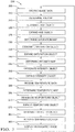
- Fig. 3 illustrates a method 300 to provide a notification to an operator 20 of a vehicle 12 that an object 14 is proximate to the vehicle 12.
- the notification is generally based on image data 26 from a visible light camera 16 mounted on the vehicle 12 in a manner effective to have a camera field of view 22 of a particular area about the vehicle 12.
- the notification is also based on temperature data 28 from a multiple zone temperature sensor 18 mounted on the vehicle 12 in a manner effective to have a sensor field of view 24 similar to the camera field of view 22.
- the system 10 seeks to detect the object 14 by examining various arrays of data cells that indicate attributes such as the hue values, saturation values, and intensity values as detected by pixels of the camera. If the resolution of the camera is greater than is necessary to detect the object 14, the values stored in each data cell of the various data arrays may be based on more than one pixel.
- the examination of these various arrays is directed to detecting a potential object by looking for instances of clusters of data having certain shapes, sizes, contrasts with surrounding backgrounds, and/or absolute values.
- temperature zone data from the sensor 18 is stored in arrays and similarly examined for instances of clusters of data having certain shapes, sizes, contrasts, and/or absolute values. Then various combinations of these arrays or maps of the image data 26 and the temperature data 28 are compared, in effect 'overlaid' on one another, to look for instances where a potential object is present in more than one map.
- Fig. 4 illustrates a non-limiting example of an example scene 40 depicting a driveway 42 and a lawn 44 behind the vehicle 12 that is occupied by an object 14 depicted in this example as a child.
- the image data 26 and the temperature data 28 show the same perspective of the scene 40 because both the camera 16 and the sensor 18 are co-located, or the signals from the camera 16 and the sensor 18 have been processed so the perspectives appear the same or very similar.
- the example child is wearing a shirt 46 and shorts 48 that are red in color, and the child's face and legs are exposed.
- step 305 may include receiving visible light image data 26 from the camera 16.
- the image data 26 includes data indicative of the color of the visible light, for example hue (denotes the degree or dominant wavelength of a measured color) and saturation (denotes the amount of color contained compared to white light), and visible light intensity (denotes the brightness of the light) detected by pixels in the camera 16.
- hue denotes the degree or dominant wavelength of a measured color
- saturation denotes the amount of color contained compared to white light
- visible light intensity denotes the brightness of the light
- Step 310, DETERMINE HUE MAP may include determining a hue map characterized as an array of hue data cells. These data cells may be locations in memory within the controller 30.
- each hue data cell has a hue value based on a hue characteristic of a portion of the image data detected by of one or more of the pixels in the camera 16 corresponding to the portion of camera field of view 22.
- the hue value may be a number between zero (0) and three hundred sixty (360) where zero is used to designate red, one hundred twenty (120) is used to designate green, two hundred forty (240) is used to designate blue, three hundred sixty (360) is used to designate violet, and other intermediate values are used to designate colors of the color spectrum as is well known.
- Step 315 may include designating a hue object on an area of the hue map where a cluster of hue data cells are present that have notable hue values relative to a hue threshold and may depict a potential object having a notable size and shape.
- a hue object may be designated because a cluster of hue data cells have a hue value notably different than surrounding hue values.
- the hue values of the clusters may differ from the hue values of the backgrounds by a notable amount, for example the hue value of the clusters may differ from the background by an amount greater than 30.
- a hue object may be designated only on the basis of the hue value and regardless of how a particular hue value differs from a perceived background.
- a hue object may be designated simply because the hue values of a cluster of hue data cells is less than 20 and so is substantially red, or the hue values correspond to various flesh tones.
- a cluster of data cells may be designated a hue object because the cluster is neither too small because the object is too small or too far away to be a concern, or too large, for example when the entire camera field of view is red because the vehicle is backed against a red building.
- the specific thresholds are determined based on the area covered by the camera field of view 22, the resolution or number of pixels of the camera 16, where the camera 16 is mounted on the vehicle 12, range based upon vehicle movement mechanics, operator reaction time, and many other considerations including empirical testing, as will be recognized by those in the art.
- Fig. 5 illustrates a non-limiting example of a hue object 50 present on a hue map 52 corresponding to the child (object 14) illustrated in Fig. 4 .
- the driveway 42 and lawn 44 of Fig. 4 are not depicted by the hue map 52 because they would be excluded by object detection rules based on hue value, size, and/or shape of the driveway 42 and the lawn 44.
- the illustration suggests that the hue value for the shirt and shorts is different than the hue value for the face and legs.
- the effects of pixilation are not shown only for the purpose of simplifying the illustrations.
- Step 320 EXPAND HUE OBJECT
- Step 320 EXPAND HUE OBJECT
- expanding the number of data cells associated with a potential object helps to avoid a failure to detect small objects because of misalignment of the camera field of view 22 and the sensor field of view 24.
- the percentage or degree of expansion will typically be greater for small potential objects as compared to large potential objects.
- Fig. 6 illustrates a non-limiting example of the effect of expanding the hue object 50 to become an expanded hue object 54.
- a way to accomplish this is to change the hue values of data cells on the hue map 52 proximate to and outside the hue object 50 to a data cell value that corresponds to that of the hue object 50.
- the illustration suggests that all of the data cell hue values of the expanded hue object 54 are the same only for the purpose of simplifying the illustration.
- the expanded hue object 54 could be depicted by data cell values that help to maintain the distinction of the data cells for the shirt 46 and shorts 48 from the face and legs of the child.
- a potential object will appear smaller on a map of the image the further away the potential object is from the camera 16.
- the location of the bottom of the potential object on the map may be used as an indication of a distance between the camera 16 and the potential object.
- the location on the map of the bottom of the potential object may also be used to determine the percentage or degree of expansion that should be applied to an object.
- images of long narrow objects such as flag poles and curbs may be expanded to a different percentage or degree of expansion than an object having an aspect ratio closer to one-to-one such as a child standing behind the vehicle.
- the amount or factor of expansion applied to an object may be greater at the bottom than at the top in order to compensate for the lower rows of an object map being potentially closer to the camera 16 than the upper rows of the object map.
- Step 325, DETERMINE SATURATION MAP may include d) determining a saturation map characterized as an array of saturation data cells, wherein each saturation data cell has a saturation value based on a saturation characteristic of the image data detected by of one or more of the pixels.
- the saturation value may be indicated by a number between 0 and 100 corresponding to a percentage of color saturation detected by the corresponding pixel in the camera 16.
- Step 330 DESIGNATE SATUATION OBJECT, may include e) designating a saturation object on an area of the saturation map where a cluster of saturation data cells are present that have notable saturation values relative to a saturation threshold.
- Fig. 4 as the example scene 40
- Fig. 5 may also be used as an example saturation map (52) depicting a saturation object (50).
- the saturation object may be determined based on a cluster of saturation data cells having saturation values that stand in distinct contrast to the saturation values associated with the surrounding background.
- the saturation value of the shirt 46 and shorts 48, or the saturation values associated with the flesh tones of the child's face and legs may be notably different that the saturation values for the driveway 42.
- the saturation values for the shirt 46 and the shorts 48 may be such that only those objects are designated as a saturation object because some flesh tones of some persons would not have particularly notable saturation values.
- Step 335 EXPAND SATURATION OBJECT, like the other expand steps, is an optional step that may include increasing the number of saturation data cells designated as part of the saturation object based on one or more of a saturation object shape and a saturation object size.
- an expanded saturation object may be comparable to the expanded hue object of Fig. 6 , and that the advantage of expanding the saturation object is the same as the hue object, that being reducing the risk of failing to have a saturation object intersect with a portion of the thermal object described below.
- Step 340, DETERMINE INTENSITY MAP may include f) determining an intensity map characterized as an array of intensity data cells, wherein each intensity data cell has an intensity value based on an intensity characteristic of the image data detected by of one or more of the pixels.
- the intensity value may be expressed as a number between 0 and 100 to indicate a relative value, or the intensity value may be expressed as a number corresponding to a particular unit of intensity measure per unit area such as illuminance in lumens per square centimeter.
- Step 345 DESIGNATE INTENSITY OBJECT
- the intensity object may be determined based on a cluster of intensity data cells having intensity values that stand in distinct contrast to the intensity values associated with the surrounding background. For example the intensity value of the shirt 46 and shorts 48, or the intensity values associated with the flesh tones of the child's face and legs, may be notably different than the intensity values for the driveway 42.
- the intensity values for the shirt 46 and the shorts 48 may be such that only those objects are designated as a saturation object because some flesh tones of some persons would not have particularly notable intensity values.
- Step 350 EXPAND INTENSITY OBJECT, like the other expand steps, is an optional step that may include increasing the number of intensity data cells designated as the intensity object based on one or more of an intensity object shape and an intensity object size.
- an expanded intensity object may be comparable to the expanded hue object of Fig. 6 , and that the advantage of expanding the intensity object is the same as the hue object, that being reducing the risk of failing to have an intensity object intersect with a portion of the thermal object described below.
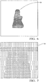
- Step 355, RECEIVE TEMPERATURE DATA may include h) receiving temperature data from the multiple zone temperature sensor (the sensor 18), wherein said temperature data includes a zone temperature value for each of the multiple zones.
- Fig. 7 illustrates a non-limiting example of temperature values detected by a 32 by 31 thermopile array. It is understood that the zone temperature values would correspond to an actual temperature; however, for the purpose of simplifying the illustration, the thermopiles directed to areas corresponding to the driveway 42 are labeled as '0', the thermopiles directed to areas corresponding to the lawn 44 are labeled as '1', the thermopiles directed to areas corresponding to the object 14 are labeled as 'X'.
- Step 360 DETERMINE TEMPERATURE MAP, may include i) determining a temperature map 56 characterized as an array of temperature data cells, wherein each temperature data cell has a temperature value based on a temperature characteristic of one or more of the multiple zones. Determining the temperature map 56 may include determining a background temperature value based on the zone temperature value of at least one zone, or the average value of several selected zones, or based on an average value of all the temperature zones. Determining a differential temperature value for each zone may be based on a difference between the background temperature value and the corresponding zone temperature value.
- Step 365, DESIGNATE TEMPERATURE OBJECT may include j) designating a temperature object 60 ( Fig. 8 ) on an area of the temperature map where a cluster of temperature data cells are present that have notable temperature values relative to a temperature threshold.
- the temperature data illustrated in Fig. 7 may be converted into a thermal binary map 58 based on a comparison of the differential temperature value to a differential temperature threshold value.
- Fig. 8 illustrates a non-limiting example of the temperature object 60 based on such the thermal binary map that may arise based on the example scene 40 of Fig. 4 .
- Step 370 EXPAND TEMPERATURE OBJECT, like the other expand steps, is an optional step that may include increasing the number of temperature data cells designated as the temperature object 60 based on one or more of a temperature object shape and a temperature object size.
- an expanded intensity object may be comparable to the expanded hue object of Fig. 6 ; however the expanded temperature object may still have the highly pixelated shape shown in Fig. 8 , or other image processing may be used to give the expanded temperature object a more rounded, smooth shape.
- the advantage of expanding the temperature object is the same as the hue object, that being reducing the risk of failing to have the temperature object intersect with a portion of the camera based objects (hue, saturation, and intensity) described above.
- Step 375, DESIGNATE DETECTED OBJECT may include k) designating a detected object 62 on an area of an object map where the hue object, the intensity object, and the temperature object intersect, or where the saturation object, the intensity object, and the temperature object intersect.
- Fig. 9 illustrates a non-limiting example of the detected object 62 at the intersection of the expanded hue object 54 and the temperature object 60.
- the intensity object is not illustrated only for the purpose of simplifying the illustration, but it should be understood that the intensity object could be exactly the same as the hue object. If the intensity object were different than the hue object, then it is expected that the intersection area would likely be smaller.
- Designating the detected object 62 may include other tests such as determining that the detected object 62 persists for a time longer than a persistence time threshold, for example more than 0.1 seconds, or more than three frames when the image frame rate is thirty frames per second. Designating the detected object 62 may include determining that the detected object moves at a speed less than a speed threshold representative of an object's maximum movement. This may be helpful to determine that an object will be out of the way of the vehicle 12 when backing, and so does not need to be brought to the attention of the operator 20.
- Step 380 may include the controller 30 generating or outputting a warning signal 38 when the detected object 62 is detected or confirmed.
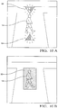
- Step 385, DISPLAY HIGHLIGHTED IMAGE may include 1) displaying on a display 32 an image from the camera 16 that includes a highlighted area selected based on the detected object 62.
- the display 32 may show an image comparable the example scene 40 shown in Fig 4 , and then highlighting a region of the image by A) flashing a red triangle 64 above and/or below the object 14 ( Fig. 10A ), B) overlaying the object 14 with a flashing red tinted region corresponding to the expanded hue object 54 shown Fig. 6 , or the temperature object 60 shown in Fig. 8 , or C) overlay the object 14 with a rectangle 66 ( Fig. 10B ) or other polygon suitable to attract the attention of the operator 20 and make it easier to for the operator to identify what the system 10 has determined is at risk of a collision.
- a system 10, a controller 30 for the system 10 and a method 300 to provide a notification to an operator 20 of a vehicle 12 that an object 14 is proximate to the vehicle 12 is provided.
- the system 10 enhances what is shown on the display 32 by fusing information from a visible light camera 16 and a multiple zone temperature sensor 18 to improve object detection and highlight the image on the display in a way so the operator 20 can more readily identify the object 14.
- potential objects detected by the camera 16 and/or the sensor 18 may be expanded to increase the likelihood that data maps of the expanded potential objects will be more likely to have intersecting potential objects and thereby reduce the risk of failing to detect an object due to misalignment of the camera 16 and sensor 18 fields of view.
Landscapes
- Engineering & Computer Science (AREA)
- Computer Vision & Pattern Recognition (AREA)
- Physics & Mathematics (AREA)
- General Physics & Mathematics (AREA)
- Theoretical Computer Science (AREA)
- Traffic Control Systems (AREA)
- Image Analysis (AREA)
- Image Processing (AREA)
Claims (13)
- Eine Steuervorrichtung (30) für ein System (10), die konfiguriert ist zum Vorsehen einer Benachrichtigung an einen Bediener (20) eines Fahrzeugs (12), dass sich ein Objekt (14) in der Nähe des Fahrzeugs (12) befindet, wobei das System (10) eine an dem Fahrzeug (12) angebrachte Kamera (16) für sichtbares Licht aufweist, die wirksam ist, um ein Kamerasichtfeld (22) zu haben, und konfiguriert ist zum Ausgeben von Bilddaten (26), die eine Farbe des sichtbaren Lichts und eine Intensität des sichtbaren Lichts angeben, die durch Pixel in der Kamera (16) erfasst werden, und einen an dem Fahrzeug (12) angebrachten Mehrzonentemperatursensor (18), der wirksam ist, um ein Sensorsichtfeld (24) ähnlich zu dem Kamerasichtfeld (22) zu haben, und konfiguriert ist zum Ausgeben von Temperaturdaten (28), die eine Zonentemperatur für jede der mehreren Zonen angeben, wobei die Steuervorrichtung (30) konfiguriert ist zuma) Empfangen von sichtbares-Licht-Bilddaten (26) von der Kamera (16), wobei die Bilddaten (26) eine Farbe des sichtbaren Lichts und eine Intensität des sichtbaren Lichts angeben, die durch Pixel in der Kamera (16) erfasst werden;b) Bestimmen einer Farbtonkarte (52), die als ein Array von Farbtondatenzellen gekennzeichnet ist, wobei jede Farbtondatenzelle einen Farbtonwert hat, der auf einer Farbtoncharakteristik der Bilddaten (26) basiert, erfasst von einem oder mehreren der Pixel;c) Bezeichnen eines Farbtonobjekts (50) in einem Bereich der Farbtonkarte (52), wo ein Cluster von Farbdatenzellen vorhanden ist, die beachtenswerte Farbtonwerte relativ zu einer Farbtonschwelle haben;d) Bestimmen einer Sättigungskarte (52), die als ein Array von Sättigungsdatenzellen gekennzeichnet ist, wobei jede Sättigungsdatenzelle einen Sättigungswert hat, der auf einer Sättigungscharakteristik der Bilddaten (26) basiert, erfasst von einem oder mehreren der Pixel;e) Bezeichnen eines Sättigungsobjekts (50) in einem Bereich der Sättigungskarte (52), wo ein Cluster von Sättigungsdatenzellen vorhanden ist, die beachtenswerte Sättigungswerte relativ zu einer Sättigungsschwelle haben;f) Bestimmen einer Intensitätskarte, die als ein Array von Intensitätsdatenzellen gekennzeichnet ist, wobei jede Intensitätsdatenzelle einen Intensitätswert hat, der auf einer Intensitätscharakteristik der Bilddaten (26) basiert, erfasst von einem oder mehreren der Pixel;g) Bezeichnen eines Intensitätsobjekts (14) in einem Bereich der Intensitätskarte, wo ein Cluster von Intensitätsdatenzellen vorhanden ist, die beachtenswerte Intensitätswerte relativ zu einer Intensitätsschwelle haben;h) Empfangen von Temperaturdaten (28) von dem Mehrzonentemperatursensor (18), wobei die Temperaturdaten (28) einen Zonentemperaturwert für jede der mehreren Zonen umfassen;i) Bestimmen einer Temperaturkarte (56), die als ein Array von Temperaturdaten(28)-Zellen gekennzeichnet ist, wobei jede Temperaturdaten(28)-Zelle einen Temperaturwert hat, der auf einer Temperaturcharakteristik von einer oder mehreren der mehreren Zonen basiert;j) Bezeichnen eines Temperaturobjekts (60) in einem Bereich der Temperaturkarte (56), wo ein Cluster von Temperaturdaten(28)-Zellen vorhanden ist, die beachtenswerte Temperaturwerte relativ zu einer Temperaturschwelle haben;k) Bezeichnen eines erfassten Objekts (62) in einem Bereich einer Objekt(14)-Karte, wo sich das Farbtonobjekt (50), das Intensitätsobjekt (14) und das Temperaturobjekt (60) schneiden, oder wo sich das Sättigungsobjekt (50), das Intensitätsobjekt (14) und das Temperaturobjekt (60) schneiden; undl) Ausgeben eines Anzeigesignals (34) entsprechend einem Bild von der Kamera (16), das einen hervorgehobenen Bereich umfasst, der basierend auf dem erfassten Objekt (62) ausgewählt ist.
- Ein System (10) zum Vorsehen einer Benachrichtigung an einen Bediener (20) eines Fahrzeugs (12), dass sich ein Objekt (14) in der Nähe des Fahrzeugs (12) befindet, wobei das System (10) aufweist:eine Kamera (16) für sichtbares Licht, die an dem Fahrzeug (12) angebracht ist, die wirksam ist, um ein Kamerasichtfeld (22) zu haben, und konfiguriert ist zum Ausgeben von Bilddaten (26), die eine Farbe des sichtbaren Lichts und eine Intensität des sichtbaren Lichts angeben, die durch Pixel in der Kamera (16) erfasst werden;einen Mehrzonentemperatursensor (18), der an dem Fahrzeug (12) angebracht ist, der wirksam ist, um ein Sensorsichtfeld (24) ähnlich zu dem Kamerasichtfeld (22) zu haben,und konfiguriert ist zum Ausgeben von Temperaturdaten (28), die eine Zonentemperatur für jede der mehreren Zonen angibt; undeine Steuervorrichtung (30) gemäß Anspruch 1.
- Das System (10) gemäß Anspruch 2, wobei die Kamera (16) mehr als 100.000 Pixel hat und der Mehrzonen-Wärmesensor (18) weniger als 1000 Zonen hat.
- Das System (10) gemäß Anspruch 2 oder Anspruch 3, wobei das System (10) weiter eine Warnanzeige (36) aufweist, die mit der Steuervorrichtung (30) gekoppelt ist, die wirksam ist zum Erzeugen eines Warnsignals (38), wenn das erfasste Objekt (62) erfasst wird.
- Ein Verfahren (300) zum Vorsehen einer Benachrichtigung an einen Bediener (20) eines Fahrzeugs (12), dass sich ein Objekt (14) in der Nähe des Fahrzeugs (12) befindet, wobei die Benachrichtigung auf Bilddaten (26) von einer Kamera (16) für sichtbares Licht basiert, die an dem Fahrzeug (12) angebracht ist, die wirksam ist, um ein Kamerasichtfeld (22) zu haben, und einen an dem Fahrzeug (12) angebrachten Mehrzonentemperatursensor (18), der wirksam ist, um ein Sensorsichtfeld (24) ähnlich zu dem Kamerasichtfeld (22) zu haben, wobei das Verfahren (300) aufweist:a) Empfangen von sichtbares-Licht-Bilddaten (26) von der Kamera (16), wobei die Bilddaten (26) eine Farbe des sichtbaren Lichts und eine Intensität des sichtbaren Lichts angeben, die durch Pixel in der Kamera (16) erfasst werden;b) Bestimmen einer Farbtonkarte (52), die als ein Array von Farbtondatenzellen gekennzeichnet ist, wobei jede Farbtondatenzelle einen Farbtonwert hat, der auf einer Farbtoncharakteristik der Bilddaten (26) basiert, erfasst von einem oder mehreren der Pixel;c) Bezeichnen eines Farbtonobjekts (50) in einem Bereich der Farbtonkarte (52), wo ein Cluster von Farbtondatenzellen vorhanden ist, die beachtenswerte Farbtonwerte relativ zu einer Farbtonschwelle haben;d) Bestimmen einer Sättigungskarte (52), die als ein Array von Sättigungsdatenzellen gekennzeichnet ist, wobei jede Sättigungsdatenzelle einen Sättigungswert hat, der auf einer Sättigungscharakteristik der Bilddaten (26) basiert, erfasst von einem oder mehreren der Pixel;e) Bezeichnen eines Sättigungsobjekts (50) in einem Bereich der Sättigungskarte (52), wo ein Cluster von Sättigungsdatenzellen vorhanden ist, die beachtenswerte Sättigungswerte relativ zu einer Sättigungsschwelle haben;f) Bestimmen einer Intensitätskarte, die als ein Array von Intensitätsdatenzellen gekennzeichnet ist, wobei jede Intensitätsdatenzelle einen Intensitätswert hat, der auf einer Intensitätscharakteristik der Bilddaten (26) basiert, erfasst von einem oder mehreren der Pixel;g) Bezeichnen eines Intensitätsobjekts (14) in einem Bereich der Intensitätskarte, wo ein Cluster von Intensitätsdatenzellen vorhanden ist, die beachtenswerte Intensitätswerte relativ zu einer Intensitätsschwelle haben;h) Empfangen von Temperaturdaten (28) von dem Mehrzonentemperatursensor (18), wobei die Temperaturdaten (28) einen Zonentemperaturwert für jede der mehreren Zonen umfassen;i) Bestimmen einer Temperaturkarte (56), die als ein Array von Temperaturdaten(28)-Zellen gekennzeichnet ist, wobei jede Temperaturdaten(28)-Zelle einen Temperaturwert hat, der auf einer Temperaturcharakteristik von einer oder mehreren der mehreren Zonen basiert;j) Bezeichnen eines Temperaturobjekts (60) in einem Bereich der Temperaturkarte (56), wo ein Cluster von Temperaturdaten(28)-Zellen vorhanden ist, die beachtenswerte Temperaturwerte relativ zu einer Temperaturschwelle haben;k) Bezeichnen eines erfassten Objekts (62) in einem Bereich einer Objekt(14)-Karte, wo sich das Farbtonobjekt (50), das Intensitätsobjekt (14) und das Temperaturobjekt (60) schneiden, oder wo sich das Sättigungsobjekt (50), das Intensitätsobjekt (14) und das Temperaturobjekt (60) schneiden; undl) Anzeigen auf einer Anzeige (32) eines Bilds von der Kamera (16), das einen hervorgehobenen Bereich umfasst, der basierend auf dem erfassten Objekt (62) ausgewählt ist.
- Das Verfahren (300) gemäß Anspruch 5, wobei das Verfahren (300) weiter ein Erzeugen eines Warnsignals (38) aufweist, wenn das erfasste Objekt (62) erfasst wird.
- Das Verfahren (300) gemäß Anspruch 5 oder 6, wobei das Verfahren (300) weiter aufweist ein Erhöhen der Anzahl von Farbtondatenzellen, die als das Farbtonobjekt (50) bezeichnet sind basierend auf einem oder mehreren aus einer Form des Farbtonobjekts (50) und einer Größe des Farbtonobjekts (50).
- Das Verfahren (300) gemäß den Ansprüchen 5 bis 7, wobei das Verfahren (300) weiter aufweist ein Erhöhen der Anzahl der Sättigungsdatenzellen, die als das Sättigungsobjekt (50) bezeichnet sind basierend auf einem oder mehreren aus einer Form des Sättigungsobjekts (50) und / oder einer Größe des Sättigungsobjekts (50).
- Das Verfahren (300) gemäß Anspruch 5 bis 8, wobei das Verfahren (300) weiter aufweist ein Erhöhen der Anzahl von Intensitätsdatenzellen, die als das Intensitätsobjekt (14) bezeichnet sind basierend auf einem oder mehreren aus einer Form des Intensitätsobjekts (14) und einer Größe des Intensitätsobjekts (14).
- Das Verfahren (300) gemäß Anspruch 5 bis 9, wobei das Verfahren (300) weiter aufweist ein Erhöhen der Anzahl von Temperaturdaten(28)-Zellen, die als das Temperaturobjekt (60) bezeichnet sind basierend auf einem oder mehreren aus einer Form des Temperaturobjekts (60) und einer Größe des Temperaturobjekts (60).
- Das Verfahren (300) gemäß Anspruch 5 bis 10, wobei der Schritt (305) des Bezeichnens eines erfassten Objekts (62) basierend auf einer Objekt(14)-Karte ein Bestimmen umfasst, dass das erfasste Objekt (62) länger als eine Fortdauerzeitschwelle besteht.
- Das Verfahren (300) gemäß Anspruch 5 bis 11, wobei der Schritt (305) des Bezeichnens, als ein erfasstes Objekt (62), eines Bereichs auf einer Objekt(14)-Karte ein Bestimmen umfasst, dass sich das erfasste Objekt (62) mit einer Geschwindigkeit bewegt, die langsamer ist als eine Geschwindigkeitsschwelle.
- Das Verfahren (300) gemäß Anspruch 5 bis 12, wobei das Bestimmen einer Temperaturkarte (56) umfasst:Bestimmen eines Hintergrundtemperaturwerts basierend auf dem Zonentemperaturwert von zumindest einer Zone;Bestimmen eines Differenztemperaturwerts für jede Zone basierend auf einer Differenz zwischen dem Hintergrundtemperaturwert und dem entsprechenden Zonentemperaturwert; undErzeugen einer thermischen Binärkarte (58) basierend auf einem Vergleich des Differenztemperaturwerts mit einem Differenztemperaturschwellenwert.
Applications Claiming Priority (1)
| Application Number | Priority Date | Filing Date | Title |
|---|---|---|---|
| US13/477,122 US8659408B2 (en) | 2012-05-22 | 2012-05-22 | Object detection system and method using a camera and a multiple zone temperature sensor |
Publications (3)
| Publication Number | Publication Date |
|---|---|
| EP2667355A2 EP2667355A2 (de) | 2013-11-27 |
| EP2667355A3 EP2667355A3 (de) | 2017-01-18 |
| EP2667355B1 true EP2667355B1 (de) | 2019-02-13 |
Family
ID=48537768
Family Applications (1)
| Application Number | Title | Priority Date | Filing Date |
|---|---|---|---|
| EP13168576.0A Active EP2667355B1 (de) | 2012-05-22 | 2013-05-21 | Objekterkennungssystem und Verfahren unter Verwendung einer Kamera und eines vielzonigen Temperatursensors |
Country Status (2)
| Country | Link |
|---|---|
| US (1) | US8659408B2 (de) |
| EP (1) | EP2667355B1 (de) |
Families Citing this family (17)
| Publication number | Priority date | Publication date | Assignee | Title |
|---|---|---|---|---|
| EP2544161B1 (de) * | 2010-03-03 | 2014-12-24 | Honda Motor Co., Ltd. | Vorrichtung zur überwachung des umgebungsbereichs eines fahrzeugs |
| CN104797913A (zh) * | 2012-09-21 | 2015-07-22 | 杭州美盛红外光电技术有限公司 | 热像诊断装置和热像诊断方法 |
| US9304042B2 (en) * | 2013-01-18 | 2016-04-05 | Delphi Technologies, Inc. | Foreign object detection system and method suitable for source resonator of wireless energy transfer system |
| JP5842110B2 (ja) * | 2013-10-10 | 2016-01-13 | パナソニックIpマネジメント株式会社 | 表示制御装置、表示制御プログラム、および記録媒体 |
| US10298859B2 (en) * | 2013-11-01 | 2019-05-21 | Flir Systems Ab | Enhanced visual representation of infrared data values |
| DE102013019305B4 (de) * | 2013-11-16 | 2024-10-02 | HELLA GmbH & Co. KGaA | Verfahren und Vorrichtung zur Bestimmung mindestens eines Steuersignals zur Steuerung einer Klimatisierungseinrichtung und Fahrzeug damit |
| US10544012B2 (en) | 2016-01-29 | 2020-01-28 | Manitowoc Crane Companies, Llc | Visual outrigger monitoring system |
| US11130658B2 (en) | 2016-11-22 | 2021-09-28 | Manitowoc Crane Companies, Llc | Optical detection and analysis of a counterweight assembly on a crane |
| US10366541B2 (en) | 2017-07-21 | 2019-07-30 | Ford Global Technologies, Llc | Vehicle backup safety mapping |
| DE102017122711A1 (de) * | 2017-09-29 | 2019-04-04 | Claas E-Systems Kgaa Mbh & Co. Kg | Verfahren für den Betrieb einer selbstfahrenden landwirtschaftlichen Arbeitsmaschine |
| DE102018203641A1 (de) * | 2018-03-12 | 2019-09-12 | Audi Ag | Verfahren zum kontaktlosen Laden einer Fahrzeugbatterie, Vorrichtung zum Überwachen eines kontaktlosen Ladevorgangs einer Fahrzeugbatterie sowie Kraftfahrzeug |
| CN111699680B (zh) * | 2018-03-15 | 2022-03-01 | Jvc建伍株式会社 | 行车记录仪、显示控制方法以及存储介质 |
| JP7020563B2 (ja) * | 2018-09-18 | 2022-02-16 | 株式会社Ihi | 異物検出装置及び送電装置 |
| US12358763B2 (en) | 2018-11-07 | 2025-07-15 | Manitowoc Crane Companies, Llc | System for determining crane status using optical and/or electromagnetic sensors |
| EP3671262B1 (de) * | 2018-12-21 | 2023-05-17 | Easymile | Verfahren und system zur handhabung von blindbereichen von abtastschichten von redundanten sensoren in einem fahrzeug |
| US12126937B2 (en) * | 2020-05-12 | 2024-10-22 | Truemeeting, Ltd. | Method and system for virtual 3D communications having multiple participants per camera |
| CN112818816B (zh) * | 2021-01-27 | 2024-03-01 | 杭州海康威视数字技术股份有限公司 | 一种温度检测方法、装置及设备 |
Family Cites Families (9)
| Publication number | Priority date | Publication date | Assignee | Title |
|---|---|---|---|---|
| US5001558A (en) | 1985-06-11 | 1991-03-19 | General Motors Corporation | Night vision system with color video camera |
| JPH01296785A (ja) | 1988-05-24 | 1989-11-30 | Fujitsu Ltd | 画像重畳装置 |
| AUPN374495A0 (en) | 1995-06-23 | 1995-07-13 | Vision Systems Limited | Security sensor arrangement |
| US7042345B2 (en) * | 1996-09-25 | 2006-05-09 | Christ G Ellis | Intelligent vehicle apparatus and method for using the apparatus |
| US20100013615A1 (en) * | 2004-03-31 | 2010-01-21 | Carnegie Mellon University | Obstacle detection having enhanced classification |
| US8531562B2 (en) * | 2004-12-03 | 2013-09-10 | Fluke Corporation | Visible light and IR combined image camera with a laser pointer |
| US7439507B2 (en) | 2005-12-29 | 2008-10-21 | Delphi Technologies, Inc. | Apparatus and method for thermal side detection in a vehicle |
| US7932835B2 (en) * | 2008-01-25 | 2011-04-26 | Delphi Technologies, Inc. | Vehicle zone detection system and method |
| US20100277298A1 (en) | 2009-04-29 | 2010-11-04 | Delphi Technologies, Inc. | Detection system and method thereof |
-
2012
- 2012-05-22 US US13/477,122 patent/US8659408B2/en active Active
-
2013
- 2013-05-21 EP EP13168576.0A patent/EP2667355B1/de active Active
Non-Patent Citations (1)
| Title |
|---|
| None * |
Also Published As
| Publication number | Publication date |
|---|---|
| EP2667355A2 (de) | 2013-11-27 |
| US20130314221A1 (en) | 2013-11-28 |
| EP2667355A3 (de) | 2017-01-18 |
| US8659408B2 (en) | 2014-02-25 |
Similar Documents
| Publication | Publication Date | Title |
|---|---|---|
| EP2667355B1 (de) | Objekterkennungssystem und Verfahren unter Verwendung einer Kamera und eines vielzonigen Temperatursensors | |
| US11745755B2 (en) | Vehicular driving assist system with driver monitoring | |
| US10896335B2 (en) | Adaptive transparency of virtual vehicle in simulated imaging system | |
| CN102782740B (zh) | 车辆周围监测装置 | |
| KR101888960B1 (ko) | 도로 평탄도 측정 장치 및 방법 | |
| US9691283B2 (en) | Obstacle alert device | |
| CN108859959A (zh) | 车辆环境成像系统和方法 | |
| US20120050024A1 (en) | Vehicle camera system | |
| US20150239396A1 (en) | Method and information system for filtering object information | |
| US11708032B2 (en) | Driving support device | |
| US11745654B2 (en) | Method and apparatus for object alert for rear vehicle sensing | |
| EP3002158B1 (de) | Heckkamera mit gps zur bildspeicherung und -wiederauffindung | |
| JP2009025910A (ja) | 障害物検出装置、障害物検出システム及び障害物検出方法 | |
| EP3185179A1 (de) | Optisches mehrfach-bildgeber-fahrzeugsensorsystem | |
| EP2869021B1 (de) | Optisches Fahrzeugsensorsystem mit mehreren Bildgebern | |
| US10540756B2 (en) | Vehicle vision system with lens shading correction | |
| JP2011227657A (ja) | 車両の周辺を監視する装置 | |
| JP2009154775A (ja) | 注意喚起装置 | |
| US20160107576A1 (en) | Multiple imager vehicle optical sensor system | |
| KR20160034669A (ko) | 차량의 주변 감시 장치 및 방법 | |
| US10688929B2 (en) | Driving assistance system and method of enhancing a driver's vision | |
| WO2022195970A1 (ja) | 警告装置及び警告方法 | |
| CN112470465A (zh) | 俯瞰图像生成装置、俯瞰图像生成方法以及程序 | |
| WO2024249384A1 (en) | Aid to pavement marking detection in wet conditions | |
| Fang et al. | A New Night Visionary Pedestrian Detection and Warning Systems |
Legal Events
| Date | Code | Title | Description |
|---|---|---|---|
| PUAI | Public reference made under article 153(3) epc to a published international application that has entered the european phase |
Free format text: ORIGINAL CODE: 0009012 |
|
| AK | Designated contracting states |
Kind code of ref document: A2 Designated state(s): AL AT BE BG CH CY CZ DE DK EE ES FI FR GB GR HR HU IE IS IT LI LT LU LV MC MK MT NL NO PL PT RO RS SE SI SK SM TR |
|
| AX | Request for extension of the european patent |
Extension state: BA ME |
|
| PUAL | Search report despatched |
Free format text: ORIGINAL CODE: 0009013 |
|
| AK | Designated contracting states |
Kind code of ref document: A3 Designated state(s): AL AT BE BG CH CY CZ DE DK EE ES FI FR GB GR HR HU IE IS IT LI LT LU LV MC MK MT NL NO PL PT RO RS SE SI SK SM TR |
|
| AX | Request for extension of the european patent |
Extension state: BA ME |
|
| RIC1 | Information provided on ipc code assigned before grant |
Ipc: G06T 7/00 20170101AFI20161209BHEP |
|
| STAA | Information on the status of an ep patent application or granted ep patent |
Free format text: STATUS: REQUEST FOR EXAMINATION WAS MADE |
|
| 17P | Request for examination filed |
Effective date: 20170718 |
|
| RBV | Designated contracting states (corrected) |
Designated state(s): AL AT BE BG CH CY CZ DE DK EE ES FI FR GB GR HR HU IE IS IT LI LT LU LV MC MK MT NL NO PL PT RO RS SE SI SK SM TR |
|
| GRAP | Despatch of communication of intention to grant a patent |
Free format text: ORIGINAL CODE: EPIDOSNIGR1 |
|
| STAA | Information on the status of an ep patent application or granted ep patent |
Free format text: STATUS: GRANT OF PATENT IS INTENDED |
|
| INTG | Intention to grant announced |
Effective date: 20180827 |
|
| RAP1 | Party data changed (applicant data changed or rights of an application transferred) |
Owner name: APTIV TECHNOLOGIES LIMITED |
|
| GRAS | Grant fee paid |
Free format text: ORIGINAL CODE: EPIDOSNIGR3 |
|
| GRAA | (expected) grant |
Free format text: ORIGINAL CODE: 0009210 |
|
| STAA | Information on the status of an ep patent application or granted ep patent |
Free format text: STATUS: THE PATENT HAS BEEN GRANTED |
|
| AK | Designated contracting states |
Kind code of ref document: B1 Designated state(s): AL AT BE BG CH CY CZ DE DK EE ES FI FR GB GR HR HU IE IS IT LI LT LU LV MC MK MT NL NO PL PT RO RS SE SI SK SM TR |
|
| REG | Reference to a national code |
Ref country code: GB Ref legal event code: FG4D |
|
| REG | Reference to a national code |
Ref country code: CH Ref legal event code: EP Ref country code: AT Ref legal event code: REF Ref document number: 1096633 Country of ref document: AT Kind code of ref document: T Effective date: 20190215 |
|
| REG | Reference to a national code |
Ref country code: IE Ref legal event code: FG4D |
|
| REG | Reference to a national code |
Ref country code: DE Ref legal event code: R096 Ref document number: 602013050707 Country of ref document: DE |
|
| REG | Reference to a national code |
Ref country code: LT Ref legal event code: MG4D |
|
| REG | Reference to a national code |
Ref country code: NL Ref legal event code: MP Effective date: 20190213 |
|
| PG25 | Lapsed in a contracting state [announced via postgrant information from national office to epo] |
Ref country code: LT Free format text: LAPSE BECAUSE OF FAILURE TO SUBMIT A TRANSLATION OF THE DESCRIPTION OR TO PAY THE FEE WITHIN THE PRESCRIBED TIME-LIMIT Effective date: 20190213 Ref country code: SE Free format text: LAPSE BECAUSE OF FAILURE TO SUBMIT A TRANSLATION OF THE DESCRIPTION OR TO PAY THE FEE WITHIN THE PRESCRIBED TIME-LIMIT Effective date: 20190213 Ref country code: FI Free format text: LAPSE BECAUSE OF FAILURE TO SUBMIT A TRANSLATION OF THE DESCRIPTION OR TO PAY THE FEE WITHIN THE PRESCRIBED TIME-LIMIT Effective date: 20190213 Ref country code: NO Free format text: LAPSE BECAUSE OF FAILURE TO SUBMIT A TRANSLATION OF THE DESCRIPTION OR TO PAY THE FEE WITHIN THE PRESCRIBED TIME-LIMIT Effective date: 20190513 Ref country code: PT Free format text: LAPSE BECAUSE OF FAILURE TO SUBMIT A TRANSLATION OF THE DESCRIPTION OR TO PAY THE FEE WITHIN THE PRESCRIBED TIME-LIMIT Effective date: 20190613 Ref country code: NL Free format text: LAPSE BECAUSE OF FAILURE TO SUBMIT A TRANSLATION OF THE DESCRIPTION OR TO PAY THE FEE WITHIN THE PRESCRIBED TIME-LIMIT Effective date: 20190213 |
|
| PG25 | Lapsed in a contracting state [announced via postgrant information from national office to epo] |
Ref country code: GR Free format text: LAPSE BECAUSE OF FAILURE TO SUBMIT A TRANSLATION OF THE DESCRIPTION OR TO PAY THE FEE WITHIN THE PRESCRIBED TIME-LIMIT Effective date: 20190514 Ref country code: BG Free format text: LAPSE BECAUSE OF FAILURE TO SUBMIT A TRANSLATION OF THE DESCRIPTION OR TO PAY THE FEE WITHIN THE PRESCRIBED TIME-LIMIT Effective date: 20190513 Ref country code: HR Free format text: LAPSE BECAUSE OF FAILURE TO SUBMIT A TRANSLATION OF THE DESCRIPTION OR TO PAY THE FEE WITHIN THE PRESCRIBED TIME-LIMIT Effective date: 20190213 Ref country code: IS Free format text: LAPSE BECAUSE OF FAILURE TO SUBMIT A TRANSLATION OF THE DESCRIPTION OR TO PAY THE FEE WITHIN THE PRESCRIBED TIME-LIMIT Effective date: 20190613 Ref country code: RS Free format text: LAPSE BECAUSE OF FAILURE TO SUBMIT A TRANSLATION OF THE DESCRIPTION OR TO PAY THE FEE WITHIN THE PRESCRIBED TIME-LIMIT Effective date: 20190213 Ref country code: LV Free format text: LAPSE BECAUSE OF FAILURE TO SUBMIT A TRANSLATION OF THE DESCRIPTION OR TO PAY THE FEE WITHIN THE PRESCRIBED TIME-LIMIT Effective date: 20190213 |
|
| REG | Reference to a national code |
Ref country code: AT Ref legal event code: MK05 Ref document number: 1096633 Country of ref document: AT Kind code of ref document: T Effective date: 20190213 |
|
| PG25 | Lapsed in a contracting state [announced via postgrant information from national office to epo] |
Ref country code: ES Free format text: LAPSE BECAUSE OF FAILURE TO SUBMIT A TRANSLATION OF THE DESCRIPTION OR TO PAY THE FEE WITHIN THE PRESCRIBED TIME-LIMIT Effective date: 20190213 Ref country code: AL Free format text: LAPSE BECAUSE OF FAILURE TO SUBMIT A TRANSLATION OF THE DESCRIPTION OR TO PAY THE FEE WITHIN THE PRESCRIBED TIME-LIMIT Effective date: 20190213 Ref country code: EE Free format text: LAPSE BECAUSE OF FAILURE TO SUBMIT A TRANSLATION OF THE DESCRIPTION OR TO PAY THE FEE WITHIN THE PRESCRIBED TIME-LIMIT Effective date: 20190213 Ref country code: DK Free format text: LAPSE BECAUSE OF FAILURE TO SUBMIT A TRANSLATION OF THE DESCRIPTION OR TO PAY THE FEE WITHIN THE PRESCRIBED TIME-LIMIT Effective date: 20190213 Ref country code: IT Free format text: LAPSE BECAUSE OF FAILURE TO SUBMIT A TRANSLATION OF THE DESCRIPTION OR TO PAY THE FEE WITHIN THE PRESCRIBED TIME-LIMIT Effective date: 20190213 Ref country code: SK Free format text: LAPSE BECAUSE OF FAILURE TO SUBMIT A TRANSLATION OF THE DESCRIPTION OR TO PAY THE FEE WITHIN THE PRESCRIBED TIME-LIMIT Effective date: 20190213 Ref country code: CZ Free format text: LAPSE BECAUSE OF FAILURE TO SUBMIT A TRANSLATION OF THE DESCRIPTION OR TO PAY THE FEE WITHIN THE PRESCRIBED TIME-LIMIT Effective date: 20190213 Ref country code: RO Free format text: LAPSE BECAUSE OF FAILURE TO SUBMIT A TRANSLATION OF THE DESCRIPTION OR TO PAY THE FEE WITHIN THE PRESCRIBED TIME-LIMIT Effective date: 20190213 |
|
| REG | Reference to a national code |
Ref country code: DE Ref legal event code: R097 Ref document number: 602013050707 Country of ref document: DE |
|
| PG25 | Lapsed in a contracting state [announced via postgrant information from national office to epo] |
Ref country code: SM Free format text: LAPSE BECAUSE OF FAILURE TO SUBMIT A TRANSLATION OF THE DESCRIPTION OR TO PAY THE FEE WITHIN THE PRESCRIBED TIME-LIMIT Effective date: 20190213 Ref country code: PL Free format text: LAPSE BECAUSE OF FAILURE TO SUBMIT A TRANSLATION OF THE DESCRIPTION OR TO PAY THE FEE WITHIN THE PRESCRIBED TIME-LIMIT Effective date: 20190213 |
|
| PLBE | No opposition filed within time limit |
Free format text: ORIGINAL CODE: 0009261 |
|
| STAA | Information on the status of an ep patent application or granted ep patent |
Free format text: STATUS: NO OPPOSITION FILED WITHIN TIME LIMIT |
|
| REG | Reference to a national code |
Ref country code: CH Ref legal event code: PL |
|
| PG25 | Lapsed in a contracting state [announced via postgrant information from national office to epo] |
Ref country code: AT Free format text: LAPSE BECAUSE OF FAILURE TO SUBMIT A TRANSLATION OF THE DESCRIPTION OR TO PAY THE FEE WITHIN THE PRESCRIBED TIME-LIMIT Effective date: 20190213 |
|
| 26N | No opposition filed |
Effective date: 20191114 |
|
| PG25 | Lapsed in a contracting state [announced via postgrant information from national office to epo] |
Ref country code: LI Free format text: LAPSE BECAUSE OF NON-PAYMENT OF DUE FEES Effective date: 20190531 Ref country code: CH Free format text: LAPSE BECAUSE OF NON-PAYMENT OF DUE FEES Effective date: 20190531 Ref country code: MC Free format text: LAPSE BECAUSE OF FAILURE TO SUBMIT A TRANSLATION OF THE DESCRIPTION OR TO PAY THE FEE WITHIN THE PRESCRIBED TIME-LIMIT Effective date: 20190213 |
|
| REG | Reference to a national code |
Ref country code: BE Ref legal event code: MM Effective date: 20190531 |
|
| PG25 | Lapsed in a contracting state [announced via postgrant information from national office to epo] |
Ref country code: LU Free format text: LAPSE BECAUSE OF NON-PAYMENT OF DUE FEES Effective date: 20190521 Ref country code: SI Free format text: LAPSE BECAUSE OF FAILURE TO SUBMIT A TRANSLATION OF THE DESCRIPTION OR TO PAY THE FEE WITHIN THE PRESCRIBED TIME-LIMIT Effective date: 20190213 |
|
| PG25 | Lapsed in a contracting state [announced via postgrant information from national office to epo] |
Ref country code: TR Free format text: LAPSE BECAUSE OF FAILURE TO SUBMIT A TRANSLATION OF THE DESCRIPTION OR TO PAY THE FEE WITHIN THE PRESCRIBED TIME-LIMIT Effective date: 20190213 |
|
| PG25 | Lapsed in a contracting state [announced via postgrant information from national office to epo] |
Ref country code: IE Free format text: LAPSE BECAUSE OF NON-PAYMENT OF DUE FEES Effective date: 20190521 |
|
| PG25 | Lapsed in a contracting state [announced via postgrant information from national office to epo] |
Ref country code: BE Free format text: LAPSE BECAUSE OF NON-PAYMENT OF DUE FEES Effective date: 20190531 |
|
| PG25 | Lapsed in a contracting state [announced via postgrant information from national office to epo] |
Ref country code: CY Free format text: LAPSE BECAUSE OF FAILURE TO SUBMIT A TRANSLATION OF THE DESCRIPTION OR TO PAY THE FEE WITHIN THE PRESCRIBED TIME-LIMIT Effective date: 20190213 |
|
| PG25 | Lapsed in a contracting state [announced via postgrant information from national office to epo] |
Ref country code: HU Free format text: LAPSE BECAUSE OF FAILURE TO SUBMIT A TRANSLATION OF THE DESCRIPTION OR TO PAY THE FEE WITHIN THE PRESCRIBED TIME-LIMIT; INVALID AB INITIO Effective date: 20130521 Ref country code: MT Free format text: LAPSE BECAUSE OF FAILURE TO SUBMIT A TRANSLATION OF THE DESCRIPTION OR TO PAY THE FEE WITHIN THE PRESCRIBED TIME-LIMIT Effective date: 20190213 |
|
| PG25 | Lapsed in a contracting state [announced via postgrant information from national office to epo] |
Ref country code: MK Free format text: LAPSE BECAUSE OF FAILURE TO SUBMIT A TRANSLATION OF THE DESCRIPTION OR TO PAY THE FEE WITHIN THE PRESCRIBED TIME-LIMIT Effective date: 20190213 |
|
| P01 | Opt-out of the competence of the unified patent court (upc) registered |
Effective date: 20230424 |
|
| REG | Reference to a national code |
Ref country code: DE Ref legal event code: R081 Ref document number: 602013050707 Country of ref document: DE Owner name: APTIV TECHNOLOGIES AG, CH Free format text: FORMER OWNER: APTIV TECHNOLOGIES LIMITED, ST. MICHAEL, BB |
|
| PGFP | Annual fee paid to national office [announced via postgrant information from national office to epo] |
Ref country code: DE Payment date: 20250422 Year of fee payment: 13 |
|
| PGFP | Annual fee paid to national office [announced via postgrant information from national office to epo] |
Ref country code: FR Payment date: 20250513 Year of fee payment: 13 |
|
| PGFP | Annual fee paid to national office [announced via postgrant information from national office to epo] |
Ref country code: GB Payment date: 20260313 Year of fee payment: 14 |