EP2667467A1 - Blendentüranordnung für eine elektrische Tafel - Google Patents
Blendentüranordnung für eine elektrische Tafel Download PDFInfo
- Publication number
- EP2667467A1 EP2667467A1 EP13168649.5A EP13168649A EP2667467A1 EP 2667467 A1 EP2667467 A1 EP 2667467A1 EP 13168649 A EP13168649 A EP 13168649A EP 2667467 A1 EP2667467 A1 EP 2667467A1
- Authority
- EP
- European Patent Office
- Prior art keywords
- compartment door
- electrical
- barrier panel
- panel
- housing
- Prior art date
- Legal status (The legal status is an assumption and is not a legal conclusion. Google has not performed a legal analysis and makes no representation as to the accuracy of the status listed.)
- Granted
Links
Images




Classifications
-
- H—ELECTRICITY
- H02—GENERATION; CONVERSION OR DISTRIBUTION OF ELECTRIC POWER
- H02B—BOARDS, SUBSTATIONS OR SWITCHING ARRANGEMENTS FOR THE SUPPLY OR DISTRIBUTION OF ELECTRIC POWER
- H02B1/00—Frameworks, boards, panels, desks, casings; Details of substations or switching arrangements
- H02B1/26—Casings; Parts thereof or accessories therefor
- H02B1/30—Cabinet-type casings; Parts thereof or accessories therefor
- H02B1/38—Hinged covers or doors
Definitions
- the field of the invention relates generally to a door assembly for an electrical panel, and more particularly, to shutter door assemblies for electrical panels that allow selective access to electrical connections of the electrical panel.
- Electrical panels are typically metallic boxes that house multiple electrical connections, fuses, circuit breakers and other electrical distribution devices. Electrical panels may be commonly referred to as a circuit breaker panel, a breaker panel, a load center, a service panel, a breaker box, an electrical box or the like.
- electrical panels typically include one or more plug-in type receptacles that allow a user to connect a cable to the receptacle.
- the receptacles are accessible by a hinged solid metal plate door that must be opened to provide access to the receptacles.
- the metal plate door acts as a protective covering for the receptacles when not in use.
- the door can not be fully closed due to cable entry, which creates a safety hazard.
- animals may enter and cause damage.
- the panel may also be exposed to potential environmental damage or vandalism damage when the door is fully or partially open.
- an electrical panel in one aspect, includes a housing configured to house one or more electrical components that are accessible from outside the housing.
- a shutter door assembly is coupled to the housing.
- the shutter door assembly comprises a compartment door and a barrier panel slidably coupled to the compartment door.
- the barrier panel is configured to be placed in a closed position that obstructs access to the one or more electrical components through the compartment door and an open position that provides access to the one or more electrical components through the compartment door.
- a shutter door assembly for an electrical panel housing includes a compartment door configured to be coupled to the housing and having at least one opening.
- the shutter door includes a barrier panel having at least one opening slidably coupled to the compartment door.
- the barrier panel is configured to be placed in a closed position that blocks the at least one compartment door opening and an open position wherein the at least one barrier panel opening is in alignment with the at least one compartment door opening.
- a method of assembling an electrical panel includes providing a housing configured to house at least one electrical component. The method further includes coupling a shutter door assembly to the housing.
- the shutter door assembly has a compartment door having at least one opening and a barrier panel slidably coupled to the compartment door.
- the barrier panel is configured to be placed in a closed position that obstructs access to the at least one electrical component through the compartment door and an open position that provides access to the at least one electrical component through the compartment door.
- Figs. 1 and 7 illustrate an electrical panel 100 including a shutter door assembly 102.
- electrical panel 100 has a box shaped housing 104 defining a cavity therein for housing electrical components.
- a faceplate 106 is attached to a front of electrical panel 100.
- electrical panel 100 houses one or more electrical components (not shown) within the cavity of housing 104.
- One or more of the electrical components are connected to a receptacle 108 ( Fig. 7 ), for example by wiring or electrical cable (not shown).
- at least one receptacle 108 has a connector 110 ( Fig. 7 ) accessible from outside housing 104.
- at least one of connectors 110 are disposed on an outside surface of faceplate 106.
- connectors 110 are electrical connectors, such as quick-connect type electrical connectors. However, connectors 110 may be any type of connectors that allow electrical panel 100 to function as disclosed herein.
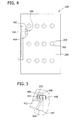
- Fig. 2 illustrates an embodiment of shutter door assembly 102.
- shutter door assembly 102 includes a compartment door 200 and a barrier panel 202, which is slidably coupled to compartment door 200.
- compartment door 200 includes one or more openings 204 extending therethrough that are aligned with connectors 110 (shown in Fig. 1 ) when shutter door assembly 102 is coupled to housing 104 (shown in Fig. 1 ). Openings 204 provide access to connectors 110 from outside housing 104.
- openings 204 are circular.
- openings 104 may be any shape that allows access to connectors 110.
- openings 204 have a shape that corresponds to a cross-sectional shape of connectors 110, for example, if connectors have a hexagonal cross-sectional shape, openings 204 will also have a hexagonal cross-sectional shape. In yet other embodiments, openings 204 are sized such that when a connecting device (not shown) passes through opening 204 to connect to connector 110, the connecting device substantially fills and/or seals opening 204.
- Shutter door assembly 102 is coupled to faceplate 106 by a coupler 206 that is attached to compartment door 200 and faceplate 106.
- Shutter door assembly 102 allows a user to access connectors 110 by sliding barrier panel 202 as described below so that connectors 110 are accessible while compartment door 200 is closed.
- coupler 206 is a hinge that allows shutter door assembly 102 to pivot relative to faceplate 106 and provides additional access to connectors 110.
- coupler 206 may be another type of fastener that attaches compartment door 200 to faceplate 106.
- Fig. 3 illustrates a rear view of shutter door assembly 100.
- Barrier panel 202 is slidably coupled to an inner side of compartment door 200 proximal to faceplate 106.
- barrier panel 202 includes a plurality of openings 300 that align with openings 204 of compartment door 200 in at least one position (e.g., an open position).
- openings 300 are complimentary with openings 204.
- barrier panel 202 is a solid panel having no openings.
- barrier panel 202 is slidably coupled to compartment door 200 via guide brackets 302 that are configured to enable barrier panel 202 to move from a closed position (shown in Figs.
- barrier panel 202 is positioned such that openings 204 are blocked by solid portions of barrier panel 202, to an open position (shown in Fig. 2 ) in which at least one opening 204 is not blocked by a solid portion of barrier panel 202.
- Guide brackets 302 maintain barrier panel 202 in a predetermined alignment with compartment door 200 during sliding.
- the open position corresponds to a position of barrier panel 202 relative to compartment door 200 such that openings 300 are aligned with openings 204, for example as shown in Fig. 2 .
- barrier panel 202 is positioned relative to compartment door 200 such that upper edge 304 is located below at least one opening 204 or lower edge 306 is located above at least one opening 204 to provide access to connectors 110.
- shutter door assembly 100 is substantially or completely watertight, such that water cannot enter through openings 204 and contact connectors 110.
- Fig. 4 illustrates a front view of shutter door assembly 100 in a closed position.
- barrier panel 202 includes a protrusion 400 and compartment door 200 includes a slot 402.
- Protrusion 400 is configured to project outwardly through slot 402, which enables a user to grasp protrusion 400, for example for use as a handle to move barrier panel 202 relative to compartment door 200.
- slot 402 is defined by an upper edge, a lower edge and a pair of side edges, and is sized such that protrusion 400 rests on a lower edge 404 when barrier panel 202 is in the open position.
- compartment door 200 includes a second protrusion 406 that aligns with protrusion 400 in at least one position.
- protrusion 400 includes a lock hole 410 (shown in Fig. 5 ) and second protrusion 406 includes a second lock hole 408 (shown in Fig. 5 ).
- lock hole 410 and second lock hole 408 are in alignment, for example in the closed position of barrier panel 202, a locking device 412 (shown in Fig. 5 ) may be inserted therethrough to lock barrier panel 202 in the closed position, and thus prevents access to connectors 110 (shown in Fig. 5 ).
- barrier panel 202 is made of a plastic material and compartment door 200 is fabricated from a metal material. In other embodiments at least one of barrier panel 202 and compartment door 200 is fabricated from an insulating material. In still other embodiments, barrier panel 202 and compartment door 200 are made of the same material.
- Fig. 6 is a flow diagram for a method of assembling an electrical panel 100.
- the method includes providing 500 a housing 104 for housing one or more electrical components.
- a faceplate 106 is coupled 502 to housing 104 to define a wall of housing 104.
- At least one electrical component is coupled 504 to a receptacle 108 having a connector 110 on the outside surface of faceplate 106.
- a shutter door assembly 102 is coupled 506 to faceplate 106.
- Shutter door assembly 102 is configured to be placed in a closed position that obstructs access to connector 110 and an open position that does not obstruct access to connector 110.
- a locking device 412 is coupled 508 to shutter door assembly 102.
Landscapes
- Engineering & Computer Science (AREA)
- Power Engineering (AREA)
- Connector Housings Or Holding Contact Members (AREA)
- Distribution Board (AREA)
- Patch Boards (AREA)
- Casings For Electric Apparatus (AREA)
Applications Claiming Priority (1)
| Application Number | Priority Date | Filing Date | Title |
|---|---|---|---|
| US13/479,699 US8791362B2 (en) | 2012-05-24 | 2012-05-24 | Shutter door assembly for an electrical panel |
Publications (2)
| Publication Number | Publication Date |
|---|---|
| EP2667467A1 true EP2667467A1 (de) | 2013-11-27 |
| EP2667467B1 EP2667467B1 (de) | 2018-03-28 |
Family
ID=48537770
Family Applications (1)
| Application Number | Title | Priority Date | Filing Date |
|---|---|---|---|
| EP13168649.5A Active EP2667467B1 (de) | 2012-05-24 | 2013-05-22 | Blendentüranordnung für eine elektrische Tafel |
Country Status (4)
| Country | Link |
|---|---|
| US (1) | US8791362B2 (de) |
| EP (1) | EP2667467B1 (de) |
| KR (1) | KR102099072B1 (de) |
| CN (1) | CN103427344A (de) |
Families Citing this family (14)
| Publication number | Priority date | Publication date | Assignee | Title |
|---|---|---|---|---|
| US11028622B2 (en) * | 2012-02-23 | 2021-06-08 | Adk Electric Corporation | Electrical panelboard guard with coupled members |
| CA2805919C (en) | 2012-02-23 | 2022-07-26 | Adk Electric Corporation | Electrical panelboard guard |
| US9531169B2 (en) | 2014-06-30 | 2016-12-27 | Eaton Corporation | Motor control center units with retractable stabs and interlocks using portal shutters |
| US9451718B2 (en) * | 2014-06-30 | 2016-09-20 | Eaton Corporation | Telescoping panels suitable for motor control center units and related motor control centers |
| CN104507285B (zh) * | 2015-01-09 | 2017-06-30 | 上海优裴伺新能源科技有限公司 | 一种通过风扇降温的电力电气柜装置 |
| CN104507287B (zh) * | 2015-01-09 | 2017-09-19 | 安徽博微智能电气有限公司 | 一种低噪音的电力电气柜装置 |
| US10186847B2 (en) | 2016-11-21 | 2019-01-22 | Eaton Intelligent Power Limited | Motor control center (MCC) units with slidable shutters |
| GB2559795B (en) | 2017-02-20 | 2020-01-22 | Ge Aviat Systems Ltd | Avionics power management panel and door assembly |
| GB2559794A (en) * | 2017-02-20 | 2018-08-22 | Ge Aviat Systems Ltd | Avionics power management panel and door assembly |
| USD826174S1 (en) * | 2017-04-12 | 2018-08-21 | Ascent Products, Llc | Access panel |
| US10742004B2 (en) | 2017-12-20 | 2020-08-11 | Eaton Intelligent Power Limited | Motor control center (MCC) units with retractable power connector and interlocks including a power connector position interlock |
| GB2570675A (en) * | 2018-02-01 | 2019-08-07 | Eaton Intelligent Power Ltd | Switchgear housing |
| CA3073017A1 (en) | 2019-02-22 | 2020-08-22 | Eaton Intelligent Power Limited | Motor control center (mcc) units with dual disconnect switches, dual operator handles, retractable power connector and interlocks |
| KR200495253Y1 (ko) * | 2021-08-11 | 2022-04-08 | 강철수 | 배전반용 도어 |
Citations (4)
| Publication number | Priority date | Publication date | Assignee | Title |
|---|---|---|---|---|
| DE3536855A1 (de) * | 1985-10-16 | 1987-04-16 | Bbc Brown Boveri & Cie | Schaltfeld mit einer leistungsschaltereinheit fuer eine elektrische mittelspannungsschalt- und verteileranlage |
| US5654871A (en) * | 1995-12-11 | 1997-08-05 | General Electric Company | Motor control center providing phase conductor access |
| DE102006012056B3 (de) * | 2006-03-08 | 2007-08-09 | Siemens Ag | Verriegelungsvorrichtung für Betätigungsöffnungen einer Schaltanlage |
| GB2485398A (en) * | 2010-11-15 | 2012-05-16 | Lmr Technologies Ltd | Movable shutter for permitting access to the interior of a cabinet |
Family Cites Families (25)
| Publication number | Priority date | Publication date | Assignee | Title |
|---|---|---|---|---|
| US4591657A (en) * | 1983-07-05 | 1986-05-27 | Masters Larry C | Tamper-proof equipment securing housing |
| US4688146A (en) * | 1986-06-16 | 1987-08-18 | General Electric Company | Molded plastic enclosure for electric service apparatus |
| US5148348A (en) * | 1991-06-17 | 1992-09-15 | Westinghouse Electric Corp. | Polymeric enclosure for electrical apparatus |
| US5419208A (en) * | 1993-01-29 | 1995-05-30 | Upchurch Scientific, Inc. | Multiport selection valve |
| ZA955835B (en) * | 1994-08-31 | 1996-02-21 | Reutech Engineering Services P | Enclosure for a circuit breaker |
| US5783775A (en) * | 1995-06-28 | 1998-07-21 | Cooper Industries, Inc. | Transformer door with corrosion resistant bottom strip |
| JP3369080B2 (ja) * | 1997-07-22 | 2003-01-20 | 富士通株式会社 | 電子装置 |
| DE20111964U1 (de) | 2001-07-19 | 2002-11-28 | Robert Bosch Gmbh, 70469 Stuttgart | Sekundärverriegelung für einen Kabelbaumstecker mit unterschiedlichen Kontaktarten |
| US6893275B2 (en) | 2003-01-29 | 2005-05-17 | Koncept Technologies Inc. | Electrical receptacle with shutter |
| DE10337055A1 (de) | 2003-08-12 | 2005-03-10 | Tyco Electronics Amp Gmbh | Elektrisches Fahrzeugtürgriff-Steckverbindungssystem |
| US7064641B2 (en) | 2004-05-18 | 2006-06-20 | Eaton Corporation | Cathedral door shutter assembly |
| US7324332B1 (en) * | 2004-09-07 | 2008-01-29 | Brent Shelton | Electrical enclosure |
| US7455538B2 (en) | 2005-08-31 | 2008-11-25 | Leviton Manufacturing Co., Inc. | Electrical wiring devices with a protective shutter |
| US7348505B2 (en) | 2005-12-21 | 2008-03-25 | General Electric Company | Shutter locking system for draw-out circuit breakers and method of assembly thereof |
| KR100797159B1 (ko) * | 2006-05-11 | 2008-01-23 | 금성제어기 주식회사 | 제어반의 리셉터클 커넥터 설치구조 |
| US7361832B2 (en) * | 2006-06-08 | 2008-04-22 | Dively Robert C | Outdoor electrical enclosure and hinge-less door assembly therefor |
| KR101082733B1 (ko) * | 2007-03-23 | 2011-11-10 | 니폰게이긴조쿠가부시키가이샤 | 전자 기기용 시험 상자 |
| US7619162B2 (en) * | 2007-06-04 | 2009-11-17 | Thomas & Betts International, Inc. | Dual-hinge recessed outdoor box and cover |
| US8018725B2 (en) | 2007-06-07 | 2011-09-13 | Tyco Electronics Corporation | Cable support bracket for an electrical component |
| US7915542B2 (en) | 2007-07-09 | 2011-03-29 | Forbis Robert C | Electrical cable support bracket |
| CN201174451Y (zh) * | 2008-01-29 | 2008-12-31 | 上海益而益电器制造有限公司 | 一种插座安全门装置及具有该安全门装置的插座 |
| JP2010263747A (ja) | 2009-05-11 | 2010-11-18 | Mitsubishi Electric Corp | 真空開閉器 |
| CN101557080B (zh) * | 2009-05-18 | 2011-06-29 | 宁波天安(集团)股份有限公司 | 一种用于高压开关柜的联锁操动装置 |
| GB201001002D0 (en) | 2010-01-22 | 2010-03-10 | Airbus Operations Ltd | A bracket for attaching an electrical cable to a vehicle |
| CN201789225U (zh) * | 2010-03-09 | 2011-04-06 | 福建天宏电气有限公司 | 高压中置柜改进型门结构 |
-
2012
- 2012-05-24 US US13/479,699 patent/US8791362B2/en active Active
-
2013
- 2013-05-22 EP EP13168649.5A patent/EP2667467B1/de active Active
- 2013-05-23 KR KR1020130058443A patent/KR102099072B1/ko active Active
- 2013-05-24 CN CN2013101959228A patent/CN103427344A/zh active Pending
Patent Citations (4)
| Publication number | Priority date | Publication date | Assignee | Title |
|---|---|---|---|---|
| DE3536855A1 (de) * | 1985-10-16 | 1987-04-16 | Bbc Brown Boveri & Cie | Schaltfeld mit einer leistungsschaltereinheit fuer eine elektrische mittelspannungsschalt- und verteileranlage |
| US5654871A (en) * | 1995-12-11 | 1997-08-05 | General Electric Company | Motor control center providing phase conductor access |
| DE102006012056B3 (de) * | 2006-03-08 | 2007-08-09 | Siemens Ag | Verriegelungsvorrichtung für Betätigungsöffnungen einer Schaltanlage |
| GB2485398A (en) * | 2010-11-15 | 2012-05-16 | Lmr Technologies Ltd | Movable shutter for permitting access to the interior of a cabinet |
Also Published As
| Publication number | Publication date |
|---|---|
| CN103427344A (zh) | 2013-12-04 |
| US20130313016A1 (en) | 2013-11-28 |
| EP2667467B1 (de) | 2018-03-28 |
| US8791362B2 (en) | 2014-07-29 |
| KR20130132311A (ko) | 2013-12-04 |
| KR102099072B1 (ko) | 2020-04-09 |
Similar Documents
| Publication | Publication Date | Title |
|---|---|---|
| US8791362B2 (en) | Shutter door assembly for an electrical panel | |
| US8975863B2 (en) | Charging station for use in charging electrically powered vehicles | |
| CA2932228C (en) | Window for bottom access to an electrical meter center | |
| US9564741B1 (en) | One axis shutter with a pin-based bus system for miniature circuit breaker load centers | |
| KR102431932B1 (ko) | 패널 유니트가 구비된 mcc | |
| MX2010008265A (es) | Encerramiento de componente electrico. | |
| CN103548221B (zh) | 用于插入或可抽出单元的触点的柔性盖 | |
| EP2312707B1 (de) | Stromversorgungseinrichtung sowie Verfahren zum Montieren einer Stromversorgungseinrichtung | |
| EP3038127A1 (de) | Sicher zu verwendendes schalttafelverschlusssystem mit schlüssel | |
| KR200455528Y1 (ko) | 통신 보안 시스템 박스 | |
| US7287990B1 (en) | Method and apparatus for grounding a cable | |
| KR200465224Y1 (ko) | 전력 및 통신 통합분전반 | |
| US9437385B1 (en) | Miniature circuit breaker for a no-touch load center | |
| JP6953174B2 (ja) | キャビネット | |
| JP6814675B2 (ja) | 路上低圧分岐箱 | |
| JP4557249B2 (ja) | 分電盤 | |
| US11075506B2 (en) | Maintenance latch for switchgear shutter | |
| JP6869805B2 (ja) | キャビネット | |
| JP2013121227A (ja) | 金属閉鎖形スイッチギヤ | |
| JP2012110223A (ja) | コントロールセンター | |
| CN208209323U (zh) | 一种配电箱 | |
| US20070194672A1 (en) | Compartmentalized power distribution equipment enclosure | |
| JP5341119B2 (ja) | 電子機器の筐体および電源分離型増幅器 | |
| EP3200296B1 (de) | Mobile stromverteilungsanordnung | |
| KR100721987B1 (ko) | 구조가 개선된 광단자함 |
Legal Events
| Date | Code | Title | Description |
|---|---|---|---|
| PUAI | Public reference made under article 153(3) epc to a published international application that has entered the european phase |
Free format text: ORIGINAL CODE: 0009012 |
|
| AK | Designated contracting states |
Kind code of ref document: A1 Designated state(s): AL AT BE BG CH CY CZ DE DK EE ES FI FR GB GR HR HU IE IS IT LI LT LU LV MC MK MT NL NO PL PT RO RS SE SI SK SM TR |
|
| AX | Request for extension of the european patent |
Extension state: BA ME |
|
| 17P | Request for examination filed |
Effective date: 20140527 |
|
| RBV | Designated contracting states (corrected) |
Designated state(s): AL AT BE BG CH CY CZ DE DK EE ES FI FR GB GR HR HU IE IS IT LI LT LU LV MC MK MT NL NO PL PT RO RS SE SI SK SM TR |
|
| 17Q | First examination report despatched |
Effective date: 20140722 |
|
| GRAP | Despatch of communication of intention to grant a patent |
Free format text: ORIGINAL CODE: EPIDOSNIGR1 |
|
| INTG | Intention to grant announced |
Effective date: 20170217 |
|
| GRAJ | Information related to disapproval of communication of intention to grant by the applicant or resumption of examination proceedings by the epo deleted |
Free format text: ORIGINAL CODE: EPIDOSDIGR1 |
|
| INTC | Intention to grant announced (deleted) | ||
| GRAP | Despatch of communication of intention to grant a patent |
Free format text: ORIGINAL CODE: EPIDOSNIGR1 |
|
| INTG | Intention to grant announced |
Effective date: 20170906 |
|
| GRAS | Grant fee paid |
Free format text: ORIGINAL CODE: EPIDOSNIGR3 |
|
| GRAA | (expected) grant |
Free format text: ORIGINAL CODE: 0009210 |
|
| AK | Designated contracting states |
Kind code of ref document: B1 Designated state(s): AL AT BE BG CH CY CZ DE DK EE ES FI FR GB GR HR HU IE IS IT LI LT LU LV MC MK MT NL NO PL PT RO RS SE SI SK SM TR |
|
| REG | Reference to a national code |
Ref country code: GB Ref legal event code: FG4D |
|
| REG | Reference to a national code |
Ref country code: CH Ref legal event code: EP |
|
| REG | Reference to a national code |
Ref country code: AT Ref legal event code: REF Ref document number: 984221 Country of ref document: AT Kind code of ref document: T Effective date: 20180415 |
|
| REG | Reference to a national code |
Ref country code: IE Ref legal event code: FG4D |
|
| REG | Reference to a national code |
Ref country code: DE Ref legal event code: R096 Ref document number: 602013034982 Country of ref document: DE |
|
| PG25 | Lapsed in a contracting state [announced via postgrant information from national office to epo] |
Ref country code: LT Free format text: LAPSE BECAUSE OF FAILURE TO SUBMIT A TRANSLATION OF THE DESCRIPTION OR TO PAY THE FEE WITHIN THE PRESCRIBED TIME-LIMIT Effective date: 20180328 Ref country code: NO Free format text: LAPSE BECAUSE OF FAILURE TO SUBMIT A TRANSLATION OF THE DESCRIPTION OR TO PAY THE FEE WITHIN THE PRESCRIBED TIME-LIMIT Effective date: 20180628 Ref country code: HR Free format text: LAPSE BECAUSE OF FAILURE TO SUBMIT A TRANSLATION OF THE DESCRIPTION OR TO PAY THE FEE WITHIN THE PRESCRIBED TIME-LIMIT Effective date: 20180328 Ref country code: FI Free format text: LAPSE BECAUSE OF FAILURE TO SUBMIT A TRANSLATION OF THE DESCRIPTION OR TO PAY THE FEE WITHIN THE PRESCRIBED TIME-LIMIT Effective date: 20180328 |
|
| REG | Reference to a national code |
Ref country code: NL Ref legal event code: MP Effective date: 20180328 |
|
| REG | Reference to a national code |
Ref country code: LT Ref legal event code: MG4D |
|
| PG25 | Lapsed in a contracting state [announced via postgrant information from national office to epo] |
Ref country code: LV Free format text: LAPSE BECAUSE OF FAILURE TO SUBMIT A TRANSLATION OF THE DESCRIPTION OR TO PAY THE FEE WITHIN THE PRESCRIBED TIME-LIMIT Effective date: 20180328 Ref country code: SE Free format text: LAPSE BECAUSE OF FAILURE TO SUBMIT A TRANSLATION OF THE DESCRIPTION OR TO PAY THE FEE WITHIN THE PRESCRIBED TIME-LIMIT Effective date: 20180328 Ref country code: GR Free format text: LAPSE BECAUSE OF FAILURE TO SUBMIT A TRANSLATION OF THE DESCRIPTION OR TO PAY THE FEE WITHIN THE PRESCRIBED TIME-LIMIT Effective date: 20180629 Ref country code: BG Free format text: LAPSE BECAUSE OF FAILURE TO SUBMIT A TRANSLATION OF THE DESCRIPTION OR TO PAY THE FEE WITHIN THE PRESCRIBED TIME-LIMIT Effective date: 20180628 Ref country code: RS Free format text: LAPSE BECAUSE OF FAILURE TO SUBMIT A TRANSLATION OF THE DESCRIPTION OR TO PAY THE FEE WITHIN THE PRESCRIBED TIME-LIMIT Effective date: 20180328 |
|
| PG25 | Lapsed in a contracting state [announced via postgrant information from national office to epo] |
Ref country code: IT Free format text: LAPSE BECAUSE OF FAILURE TO SUBMIT A TRANSLATION OF THE DESCRIPTION OR TO PAY THE FEE WITHIN THE PRESCRIBED TIME-LIMIT Effective date: 20180328 Ref country code: AL Free format text: LAPSE BECAUSE OF FAILURE TO SUBMIT A TRANSLATION OF THE DESCRIPTION OR TO PAY THE FEE WITHIN THE PRESCRIBED TIME-LIMIT Effective date: 20180328 Ref country code: EE Free format text: LAPSE BECAUSE OF FAILURE TO SUBMIT A TRANSLATION OF THE DESCRIPTION OR TO PAY THE FEE WITHIN THE PRESCRIBED TIME-LIMIT Effective date: 20180328 Ref country code: NL Free format text: LAPSE BECAUSE OF FAILURE TO SUBMIT A TRANSLATION OF THE DESCRIPTION OR TO PAY THE FEE WITHIN THE PRESCRIBED TIME-LIMIT Effective date: 20180328 Ref country code: PL Free format text: LAPSE BECAUSE OF FAILURE TO SUBMIT A TRANSLATION OF THE DESCRIPTION OR TO PAY THE FEE WITHIN THE PRESCRIBED TIME-LIMIT Effective date: 20180328 Ref country code: RO Free format text: LAPSE BECAUSE OF FAILURE TO SUBMIT A TRANSLATION OF THE DESCRIPTION OR TO PAY THE FEE WITHIN THE PRESCRIBED TIME-LIMIT Effective date: 20180328 Ref country code: ES Free format text: LAPSE BECAUSE OF FAILURE TO SUBMIT A TRANSLATION OF THE DESCRIPTION OR TO PAY THE FEE WITHIN THE PRESCRIBED TIME-LIMIT Effective date: 20180328 |
|
| PG25 | Lapsed in a contracting state [announced via postgrant information from national office to epo] |
Ref country code: SM Free format text: LAPSE BECAUSE OF FAILURE TO SUBMIT A TRANSLATION OF THE DESCRIPTION OR TO PAY THE FEE WITHIN THE PRESCRIBED TIME-LIMIT Effective date: 20180328 Ref country code: CZ Free format text: LAPSE BECAUSE OF FAILURE TO SUBMIT A TRANSLATION OF THE DESCRIPTION OR TO PAY THE FEE WITHIN THE PRESCRIBED TIME-LIMIT Effective date: 20180328 Ref country code: SK Free format text: LAPSE BECAUSE OF FAILURE TO SUBMIT A TRANSLATION OF THE DESCRIPTION OR TO PAY THE FEE WITHIN THE PRESCRIBED TIME-LIMIT Effective date: 20180328 |
|
| REG | Reference to a national code |
Ref country code: CH Ref legal event code: PL |
|
| REG | Reference to a national code |
Ref country code: AT Ref legal event code: MK05 Ref document number: 984221 Country of ref document: AT Kind code of ref document: T Effective date: 20180328 |
|
| PG25 | Lapsed in a contracting state [announced via postgrant information from national office to epo] |
Ref country code: PT Free format text: LAPSE BECAUSE OF FAILURE TO SUBMIT A TRANSLATION OF THE DESCRIPTION OR TO PAY THE FEE WITHIN THE PRESCRIBED TIME-LIMIT Effective date: 20180730 |
|
| REG | Reference to a national code |
Ref country code: DE Ref legal event code: R097 Ref document number: 602013034982 Country of ref document: DE |
|
| REG | Reference to a national code |
Ref country code: BE Ref legal event code: MM Effective date: 20180531 |
|
| PG25 | Lapsed in a contracting state [announced via postgrant information from national office to epo] |
Ref country code: AT Free format text: LAPSE BECAUSE OF FAILURE TO SUBMIT A TRANSLATION OF THE DESCRIPTION OR TO PAY THE FEE WITHIN THE PRESCRIBED TIME-LIMIT Effective date: 20180328 Ref country code: DK Free format text: LAPSE BECAUSE OF FAILURE TO SUBMIT A TRANSLATION OF THE DESCRIPTION OR TO PAY THE FEE WITHIN THE PRESCRIBED TIME-LIMIT Effective date: 20180328 Ref country code: MC Free format text: LAPSE BECAUSE OF FAILURE TO SUBMIT A TRANSLATION OF THE DESCRIPTION OR TO PAY THE FEE WITHIN THE PRESCRIBED TIME-LIMIT Effective date: 20180328 |
|
| PLBE | No opposition filed within time limit |
Free format text: ORIGINAL CODE: 0009261 |
|
| STAA | Information on the status of an ep patent application or granted ep patent |
Free format text: STATUS: NO OPPOSITION FILED WITHIN TIME LIMIT |
|
| REG | Reference to a national code |
Ref country code: IE Ref legal event code: MM4A |
|
| GBPC | Gb: european patent ceased through non-payment of renewal fee |
Effective date: 20180628 |
|
| PG25 | Lapsed in a contracting state [announced via postgrant information from national office to epo] |
Ref country code: CH Free format text: LAPSE BECAUSE OF NON-PAYMENT OF DUE FEES Effective date: 20180531 Ref country code: LI Free format text: LAPSE BECAUSE OF NON-PAYMENT OF DUE FEES Effective date: 20180531 |
|
| 26N | No opposition filed |
Effective date: 20190103 |
|
| PG25 | Lapsed in a contracting state [announced via postgrant information from national office to epo] |
Ref country code: LU Free format text: LAPSE BECAUSE OF NON-PAYMENT OF DUE FEES Effective date: 20180522 |
|
| PG25 | Lapsed in a contracting state [announced via postgrant information from national office to epo] |
Ref country code: GB Free format text: LAPSE BECAUSE OF NON-PAYMENT OF DUE FEES Effective date: 20180628 Ref country code: FR Free format text: LAPSE BECAUSE OF NON-PAYMENT OF DUE FEES Effective date: 20180528 Ref country code: IE Free format text: LAPSE BECAUSE OF NON-PAYMENT OF DUE FEES Effective date: 20180522 |
|
| PG25 | Lapsed in a contracting state [announced via postgrant information from national office to epo] |
Ref country code: BE Free format text: LAPSE BECAUSE OF NON-PAYMENT OF DUE FEES Effective date: 20180531 Ref country code: SI Free format text: LAPSE BECAUSE OF FAILURE TO SUBMIT A TRANSLATION OF THE DESCRIPTION OR TO PAY THE FEE WITHIN THE PRESCRIBED TIME-LIMIT Effective date: 20180328 |
|
| PG25 | Lapsed in a contracting state [announced via postgrant information from national office to epo] |
Ref country code: MT Free format text: LAPSE BECAUSE OF NON-PAYMENT OF DUE FEES Effective date: 20180522 |
|
| PG25 | Lapsed in a contracting state [announced via postgrant information from national office to epo] |
Ref country code: TR Free format text: LAPSE BECAUSE OF FAILURE TO SUBMIT A TRANSLATION OF THE DESCRIPTION OR TO PAY THE FEE WITHIN THE PRESCRIBED TIME-LIMIT Effective date: 20180328 |
|
| PG25 | Lapsed in a contracting state [announced via postgrant information from national office to epo] |
Ref country code: HU Free format text: LAPSE BECAUSE OF FAILURE TO SUBMIT A TRANSLATION OF THE DESCRIPTION OR TO PAY THE FEE WITHIN THE PRESCRIBED TIME-LIMIT; INVALID AB INITIO Effective date: 20130522 |
|
| PG25 | Lapsed in a contracting state [announced via postgrant information from national office to epo] |
Ref country code: MK Free format text: LAPSE BECAUSE OF NON-PAYMENT OF DUE FEES Effective date: 20180328 Ref country code: CY Free format text: LAPSE BECAUSE OF FAILURE TO SUBMIT A TRANSLATION OF THE DESCRIPTION OR TO PAY THE FEE WITHIN THE PRESCRIBED TIME-LIMIT Effective date: 20180328 |
|
| PG25 | Lapsed in a contracting state [announced via postgrant information from national office to epo] |
Ref country code: IS Free format text: LAPSE BECAUSE OF FAILURE TO SUBMIT A TRANSLATION OF THE DESCRIPTION OR TO PAY THE FEE WITHIN THE PRESCRIBED TIME-LIMIT Effective date: 20180728 |
|
| PGFP | Annual fee paid to national office [announced via postgrant information from national office to epo] |
Ref country code: DE Payment date: 20250521 Year of fee payment: 13 |