EP2668063B1 - Fundamentsystem für ladesäulen - Google Patents
Fundamentsystem für ladesäulen Download PDFInfo
- Publication number
- EP2668063B1 EP2668063B1 EP12703993.1A EP12703993A EP2668063B1 EP 2668063 B1 EP2668063 B1 EP 2668063B1 EP 12703993 A EP12703993 A EP 12703993A EP 2668063 B1 EP2668063 B1 EP 2668063B1
- Authority
- EP
- European Patent Office
- Prior art keywords
- charging pole
- adapter element
- foundation member
- charging
- mounting
- Prior art date
- Legal status (The legal status is an assumption and is not a legal conclusion. Google has not performed a legal analysis and makes no representation as to the accuracy of the status listed.)
- Active
Links
Images



Classifications
-
- B—PERFORMING OPERATIONS; TRANSPORTING
- B60—VEHICLES IN GENERAL
- B60L—PROPULSION OF ELECTRICALLY-PROPELLED VEHICLES; SUPPLYING ELECTRIC POWER FOR AUXILIARY EQUIPMENT OF ELECTRICALLY-PROPELLED VEHICLES; ELECTRODYNAMIC BRAKE SYSTEMS FOR VEHICLES IN GENERAL; MAGNETIC SUSPENSION OR LEVITATION FOR VEHICLES; MONITORING OPERATING VARIABLES OF ELECTRICALLY-PROPELLED VEHICLES; ELECTRIC SAFETY DEVICES FOR ELECTRICALLY-PROPELLED VEHICLES
- B60L53/00—Methods of charging batteries, specially adapted for electric vehicles; Charging stations or on-board charging equipment therefor; Exchange of energy storage elements in electric vehicles
- B60L53/30—Constructional details of charging stations
- B60L53/31—Charging columns specially adapted for electric vehicles
-
- E—FIXED CONSTRUCTIONS
- E04—BUILDING
- E04H—BUILDINGS OR LIKE STRUCTURES FOR PARTICULAR PURPOSES; SWIMMING OR SPLASH BATHS OR POOLS; MASTS; FENCING; TENTS OR CANOPIES, IN GENERAL
- E04H12/00—Towers; Masts or poles; Chimney stacks; Water-towers; Methods of erecting such structures
- E04H12/22—Sockets or holders for poles or posts
-
- E—FIXED CONSTRUCTIONS
- E04—BUILDING
- E04H—BUILDINGS OR LIKE STRUCTURES FOR PARTICULAR PURPOSES; SWIMMING OR SPLASH BATHS OR POOLS; MASTS; FENCING; TENTS OR CANOPIES, IN GENERAL
- E04H12/00—Towers; Masts or poles; Chimney stacks; Water-towers; Methods of erecting such structures
- E04H12/22—Sockets or holders for poles or posts
- E04H12/2253—Mounting poles or posts to the holder
- E04H12/2261—Mounting poles or posts to the holder on a flat base
-
- H—ELECTRICITY
- H02—GENERATION; CONVERSION OR DISTRIBUTION OF ELECTRIC POWER
- H02G—INSTALLATION OF ELECTRIC CABLES OR LINES, OR OF COMBINED OPTICAL AND ELECTRIC CABLES OR LINES
- H02G3/00—Installations of electric cables or lines or protective tubing therefor in or on buildings, equivalent structures or vehicles
- H02G3/02—Details
- H02G3/04—Protective tubing or conduits, e.g. cable ladders or cable troughs
- H02G3/0493—Service poles
-
- H—ELECTRICITY
- H02—GENERATION; CONVERSION OR DISTRIBUTION OF ELECTRIC POWER
- H02G—INSTALLATION OF ELECTRIC CABLES OR LINES, OR OF COMBINED OPTICAL AND ELECTRIC CABLES OR LINES
- H02G9/00—Installations of electric cables or lines in or on the ground or water
- H02G9/10—Installations of electric cables or lines in or on the ground or water in cable chambers, e.g. in manhole or in handhole
-
- H—ELECTRICITY
- H02—GENERATION; CONVERSION OR DISTRIBUTION OF ELECTRIC POWER
- H02J—ELECTRIC POWER NETWORKS; CIRCUIT ARRANGEMENTS OR SYSTEMS FOR SUPPLYING OR DISTRIBUTING ELECTRIC POWER; SYSTEMS FOR STORING ELECTRIC ENERGY
- H02J7/00—Circuit arrangements for charging or discharging batteries or for supplying loads from batteries
- H02J7/70—Circuit arrangements for charging or discharging batteries or for supplying loads from batteries characterised by the mechanical construction
-
- H—ELECTRICITY
- H02—GENERATION; CONVERSION OR DISTRIBUTION OF ELECTRIC POWER
- H02G—INSTALLATION OF ELECTRIC CABLES OR LINES, OR OF COMBINED OPTICAL AND ELECTRIC CABLES OR LINES
- H02G9/00—Installations of electric cables or lines in or on the ground or water
- H02G9/02—Installations of electric cables or lines in or on the ground or water laid directly in or on the ground, river-bed or sea-bottom; Coverings therefor, e.g. tile
-
- H—ELECTRICITY
- H02—GENERATION; CONVERSION OR DISTRIBUTION OF ELECTRIC POWER
- H02J—ELECTRIC POWER NETWORKS; CIRCUIT ARRANGEMENTS OR SYSTEMS FOR SUPPLYING OR DISTRIBUTING ELECTRIC POWER; SYSTEMS FOR STORING ELECTRIC ENERGY
- H02J2105/00—Networks for supplying or distributing electric power characterised by their spatial reach or by the load
- H02J2105/30—Networks for supplying or distributing electric power characterised by their spatial reach or by the load the load networks being external to vehicles, i.e. exchanging power with vehicles
- H02J2105/33—Networks for supplying or distributing electric power characterised by their spatial reach or by the load the load networks being external to vehicles, i.e. exchanging power with vehicles exchanging power with road vehicles
- H02J2105/37—Networks for supplying or distributing electric power characterised by their spatial reach or by the load the load networks being external to vehicles, i.e. exchanging power with vehicles exchanging power with road vehicles exchanging power with electric vehicles [EV] or with hybrid electric vehicles [HEV]
-
- Y—GENERAL TAGGING OF NEW TECHNOLOGICAL DEVELOPMENTS; GENERAL TAGGING OF CROSS-SECTIONAL TECHNOLOGIES SPANNING OVER SEVERAL SECTIONS OF THE IPC; TECHNICAL SUBJECTS COVERED BY FORMER USPC CROSS-REFERENCE ART COLLECTIONS [XRACs] AND DIGESTS
- Y02—TECHNOLOGIES OR APPLICATIONS FOR MITIGATION OR ADAPTATION AGAINST CLIMATE CHANGE
- Y02T—CLIMATE CHANGE MITIGATION TECHNOLOGIES RELATED TO TRANSPORTATION
- Y02T10/00—Road transport of goods or passengers
- Y02T10/60—Other road transportation technologies with climate change mitigation effect
- Y02T10/70—Energy storage systems for electromobility, e.g. batteries
-
- Y—GENERAL TAGGING OF NEW TECHNOLOGICAL DEVELOPMENTS; GENERAL TAGGING OF CROSS-SECTIONAL TECHNOLOGIES SPANNING OVER SEVERAL SECTIONS OF THE IPC; TECHNICAL SUBJECTS COVERED BY FORMER USPC CROSS-REFERENCE ART COLLECTIONS [XRACs] AND DIGESTS
- Y02—TECHNOLOGIES OR APPLICATIONS FOR MITIGATION OR ADAPTATION AGAINST CLIMATE CHANGE
- Y02T—CLIMATE CHANGE MITIGATION TECHNOLOGIES RELATED TO TRANSPORTATION
- Y02T10/00—Road transport of goods or passengers
- Y02T10/60—Other road transportation technologies with climate change mitigation effect
- Y02T10/7072—Electromobility specific charging systems or methods for batteries, ultracapacitors, supercapacitors or double-layer capacitors
-
- Y—GENERAL TAGGING OF NEW TECHNOLOGICAL DEVELOPMENTS; GENERAL TAGGING OF CROSS-SECTIONAL TECHNOLOGIES SPANNING OVER SEVERAL SECTIONS OF THE IPC; TECHNICAL SUBJECTS COVERED BY FORMER USPC CROSS-REFERENCE ART COLLECTIONS [XRACs] AND DIGESTS
- Y02—TECHNOLOGIES OR APPLICATIONS FOR MITIGATION OR ADAPTATION AGAINST CLIMATE CHANGE
- Y02T—CLIMATE CHANGE MITIGATION TECHNOLOGIES RELATED TO TRANSPORTATION
- Y02T90/00—Enabling technologies or technologies with a potential or indirect contribution to GHG emissions mitigation
- Y02T90/10—Technologies relating to charging of electric vehicles
- Y02T90/12—Electric charging stations
-
- Y—GENERAL TAGGING OF NEW TECHNOLOGICAL DEVELOPMENTS; GENERAL TAGGING OF CROSS-SECTIONAL TECHNOLOGIES SPANNING OVER SEVERAL SECTIONS OF THE IPC; TECHNICAL SUBJECTS COVERED BY FORMER USPC CROSS-REFERENCE ART COLLECTIONS [XRACs] AND DIGESTS
- Y02—TECHNOLOGIES OR APPLICATIONS FOR MITIGATION OR ADAPTATION AGAINST CLIMATE CHANGE
- Y02T—CLIMATE CHANGE MITIGATION TECHNOLOGIES RELATED TO TRANSPORTATION
- Y02T90/00—Enabling technologies or technologies with a potential or indirect contribution to GHG emissions mitigation
- Y02T90/10—Technologies relating to charging of electric vehicles
- Y02T90/14—Plug-in electric vehicles
Definitions
- the present invention generally relates to infrastructure for electric or plug-in hybrid vehicles, and more specifically devices for anchoring a charging pole to ground.
- Vehicles provided with electric motors and with batteries for powering the electric motors are becoming more and more popular.
- One reason is the ability to drive the vehicles without using combustion engines, thereby avoiding consumption of fossil fuels and emission of combustion gases.
- Modern battery technology makes it possible to store enough energy on board a vehicle to drive it using only battery power, at least shorter distances.
- battery capacity is limited and cost is high and therefore infrastructure for charging the batteries should be readily available such that the vehicle can be charged at the convenience of the driver, for example outside a shopping mall, at a public car park or at work.
- an improved infrastructure for electric vehicles would be advantageous in order to promote the occurrence of electric vehicles.
- An object of the present invention is to provide a novel device for mounting of a charging pole, which enables improved infrastructure for electric vehicles to be deployed at low risk and at low cost.
- a device for mounting of a charging pole comprising a foundation member configured to be installed below ground level, and anchoring means by which the charging pole is mountable to the foundation member and which comprises a detachable adapter element configured to fit the charging pole to the foundation member.
- Such a mounting device promotes deployment of infrastructure for charging of electric vehicles by providing a low-cost, future-proof platform for fitting charging poles from any supplier using virtually any charging technology.
- the adapter element is mounted to the foundation member below the top edge of the foundation member. This is an advantageous feature since the adapter element and the anchoring means between the adapter element and the foundation member are thereby protected by the foundation member, at least from forces coming from the side.
- the positioning of the adapter element and anchoring means inside the foundation member is advantageous since no upwards projection part may obstruct vehicles or persons passing the top of the device.
- Another advantageous feature is that since the adapter element is arranged within the foundation element it is not an obstacle when arranging the surrounding environment, e.g. a sidewalk or a parking lot.
- the device further comprises a protection unit which is attached to the adapter element and which is preferably arranged around the charging pole and extending along at least a portion of the charging pole.
- the protection unit protects the pole from any damage in case a vehicle hits the arrangement. This leads to low reparations costs and undisturbed operation time when the pole can be used for charging batteries of a vehicle.
- the device is configured for pre-installation of the charging pole and it further comprises a removable cover member configured to cover upwardly open spaces of the mounting device and to cover an inner space of the foundation member when the adapter element is detached.
- Such a mounting device promotes deployment of infrastructure for charging of electric vehicles by providing a mounting device which allows convenient and inexpensive post-installation of charging poles, since the cover member may easily be removed to allow access to the anchoring means and cable or cable pipe of said mounting device, such that a charging pole may be attached at low cost and in a short time. Further, such a mounting device allows for a longer time period between installation of the system and the time of installation of a charging pole, since the cover member protects inner parts of the mounting device from weather and damage.
- a foundation system for charging poles for electrically powered vehicles comprises a plurality of mounting devices as defined in the appended device claims.
- Each mounting device is prepared for electrical supply by means of one or more cables or cable pipes installed in ground.
- the mounting devices and the foundation system make it possible to initially install only a few charging poles at a site, such as a car park, and then easily expand the charging capacity on that site by post-fitting charging poles as demand grows.
- a site such as a car park
- post-fitting charging poles there is no need to dig holes in the street, since additional foundation members are already provided below ground and provided with means for easy provision of power to the charging poles.
- no part of the mounting device protrudes above ground level when awaiting mounting of a charging pole, it allows normal utilization of the surface under which the mounting device is buried, without reducing the aesthetics of the site.
- the meaning of 'below ground level' essentially means that it does not protrude above ground level and thereby it does not obstruct pedestrians or traffic.
- the device may be installed below ground with its top surface substantially flush with ground level.
- a method of installing a foundation system comprises the steps of: providing at least one recess in ground, providing a plurality of mounting devices in said at least one recess, providing means for electrical supply to the mounting devices, and restoring ground at said site such that the mounting devices do not protrude above ground level.
- Such a method reduces the need for construction work at a site where deployment of infrastructure for charging of electric vehicles is planned, since substantially all excavating and activities are performed once independently of when charging poles are to be deployed at said site. Hence, there is no need of repeatedly opening up the ground level when installing charging poles.
- a method of installing a charging pole to a foundation system comprises the steps of providing access to the anchoring means of the respective mounting device, providing an adapter element for fitting the charging pole to the foundation member, providing electric supply to the charging pole by means of a cable or cable pipe already provided at the mounting device, and securing the charging pole to the mounting device by means of the anchoring means.
- the foundation member is provided with first coupling means for engagement with a second coupling means of the adapter element.
- the first and second coupling means make it possible to control the relative position and rotation between the foundation member and the adapter and any thereto attached charging pole.
- An aspect of the invention relates to a mounting device for optionally mounting a charging pole to ground.
- a further aspect of the invention relates to a system comprising such mounting devices.
- an aspect of the invention relates to a method of installing the system of the invention, and another aspect of the invention relates to a method of installing a charging pole by means of a system according to the invention.
- Fig. 1 shows four charging poles 1a-d for electric vehicles mounted to ground at a pavement 2 using a system according to an embodiment of the invention.
- An electric vehicle 3 is parked next to one of the poles 1d and is connected to the pole 1 such that batteries (not shown) of the vehicle 3 can be charged.
- the poles 1a-d are connected to a grid connection 4 by four connection cables 5a-d installed below ground, preferably protected by conventional cable pipes (not shown) commonly used for underground cable installation.
- Fig. 2 shows a system according to an embodiment of the invention installed in ground 6.
- a charging pole 1 is mounted to ground using a mounting device 7a according to a first embodiment of the invention.
- the charging pole 1 is connected to a grid connection (not shown) through a cable 5 provided through the mounting device 7a.
- the system comprises a plurality of mounting devices 7a-c installed below ground 6, but only one of them 7a is currently used for mounting a charging pole 1 to ground 6. When needed, additional charging poles may easily be attached to the remaining mounting devices 7b-c without any need of excessive construction work, i.e. without digging up the street/ground 6 again.
- cables 5 and/or cable pipes 8 are connected to each mounting device 7a-c, such that it is easy to provide electricity to charging poles subsequently mounted to the mounting devices 7a-c of the system.
- the inner space below ground in each mounting device 7a-c makes it possible to fit an extra length of cable 5 below ground and to post-install a cable through a cable pipe 8 connected to the mounting device 7a-c during installation of the system.
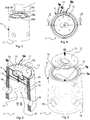
- Figs 3-6 show one of the mounting devices 7 of Fig 2 next to a charging pole 1 ready to be mounted to ground using the mounting device 7.
- the mounting device 7 comprises a substantially hollow cylindrical foundation member 9, preferably made of concrete, and anchoring means 10 by which the charging pole 1 is mountable to the foundation member 9.
- the anchoring means 10 comprises a detachable adapter element 11 configured to fit the charging pole 1 to the foundation member 9.
- a first portion 12 of the detachable adapter element 11 fits with the foundation member 9 and a second portion 13 fits with the charging pole 1.
- the peripheral top edge portion 9a of the foundation member 9 has a circular or annular recess 9b which matches and receives the peripheral portion 11a of the adapter element 11 in a close fit.
- the depth of the annual recess 9b corresponds to the thickness of the adapter element 11 such that the top surface of the same is substantially flush with the annular top surface of the top edge portion 9a of the foundation member 9.
- the first portion 12 is provided with coupling means comprising an aperture or a hole 14 configured to receive a bolt 15 for securing the adapter element 11 to the foundation member 9.
- An anchoring bar 16 is molded into the foundation member 9 for receiving the bolt 15 in a hole 25, and a threaded element 17 is provided by the anchoring bar 16 for engagement with the bolt 15.
- the bolt 15 is centrally located in the mounting device 7, such that the adapter element 11 can be rotated and subsequently fixed to hold the charging pole 1 in a desired position. Further, the anchoring bar 16 may have bent ends for stronger engagement with the foundation member 9.
- the second portion is provided with coupling means comprising four threaded holes 26a-d configured to receive bolts (not shown) for securing the mounting pole 1 to the adapter element 11 through four corresponding holes of the charging pole.
- the foundation member 9 has a plurality of entry openings or holes 18 for receiving an electric cable and/or cable pipe from the side of the mounting device.
- An electric cable 19 (shown in part with dashed lines) may be introduced into the mounting device through one of the entry holes 18 and connected to the charging pole through the inner space of the foundation member 9.
- An advantage of these entry holes 18 is that during installation of mounting devices 7 one does not have to dig as deep in order to be able to fit the cable or cable pipe into the mounting device 7. Of course, the entry holes 18 could be provided through the bottom of the foundation member 9 but then one would have to dig deeper to fit the cable 19 or cable pipe. Further, since there are a plurality of entry holes 18, more cables may be introduced into the mounting device 7 and from several directions.
- a main cable may be coupled to the mounting devices, one after the other, wherein power may be taken from the main cable at each respective mounting device for providing power to charging poles through an additional length of cable. If cables are installed like this, the total length of cable needed for connecting the system to a grid connection may be somewhat reduced as opposed to using a separate cable for each respective mounting pole stretching all the way from the grid connection to the respective pole.
- the entry holes 18 are used for connecting mounting devices 7 via cable pipes for subsequent installation of one or more cables through the cable pipes.
- the design of the charging pole and its foot or base varies depending on the choice of charging pole provider and pole model. Therefore, the upper portion of the adapter element 11 should be designed accordingly to provide suitable coupling means for coupling the charging pole 1 to the adapter element 11.
- the coupling means between the foundation member 9 and the adapter element 11 are designed such that, when the charging pole is forcefully rotated and moved, for example when hit by a car, the adapter element and/or the coupling means deforms and/or breaks without damaging or disrupting the functionality of the foundation member 9.
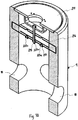
- Figs 7 and 8 show a mounting device 107 according to a second embodiment of the invention.
- This embodiment is similar to the previously described embodiment and therefore like reference numerals are increased by one hundred for easier recognition, for example 107 instead of 7, etc.
- a difference with respect to the previously described embodiment is the design of the anchoring means for attaching the charging pole to the foundation member 9.
- a central passage 120 is provided through the anchoring means 110, such that rotation of the charging pole/adapter element 1/111 will not cause the cable 5 to be cut or damaged between the anchoring bar 116 and the adapter element 111.
- the anchoring bar 116 is provided with a central hole 121 through which the cable 5 to the charging pole passes, and a matching central hole 122 is provided through a mounting plate 123 of the adapter element 111.
- the mounting plate 123 is freely rotatable relatively the rest of the adapter element 111, and may thus be secured to the anchoring bar 116 without preventing adjustability during mounting of a charging pole.
- Two bolts 115 are provided to hold the attachment plate to the anchoring bar 116 and keep them from relative rotation.
- FIG. 10 another type of anchoring bar 216 is provided, as shown in Fig. 10 .
- the anchoring bar 216 has the shape of a straight bar which may be provided with a hollow core, which leads to lower manufacturing cost and less material consumption. Between the two ends of the bar 216, there are three holes 225a-c each of which may receive a bolt 215 when engaging an adapter element 11; 111; 211 to the foundation member 9.
- an adapter element 211 similar to the adapter element 11 shown in Fig. 5 is used.
- This adapter element 11 is provided with a first element 12 which, in this case, includes one hole 14 somewhere in the middle of the first element 12, which corresponds to the hole 225b of the bar 216, for receiving a bolt 215 when mounting the adapter element 211 to the foundation member 9. Since the bar 216 shown in Fig. 10 is provided with more than one hole it is also adapted for receiving the type of mounting plate 123 shown in Fig. 8 which includes, in this case, two possible attachment holes 125, disposed one on each side of the central hole 122, which corresponds to the two holes 225a, 225c of the bar 216. At one end of the threaded holes 225a-c a threaded element 217, which is a protrusion extending in a direction away from the anchoring bar 216, is arranged for anchoring the bolt 215 to the anchoring bar 216.
- the adapter element could be secured to the foundation member by other means than a bolt, such as by welding, adhering, or snap locking (not shown). Releasable engagement is preferred since it allows the adapter element to be temporarily removed to allow it to be modified for fitting a certain type of charging pole or for mending it if it has been damaged. Alternatively, it may be replaced by another adapter element of the same type or of a different type (not shown).
- the foundation member 9 is provided with first coupling means, namely the anchoring bar 16; 116; 216 for engagement with a second coupling means of the adapter element 11; 111; 211, namely the mounting plate 123 and/or the bolt(s) 15; 115; 215. It should be understood that the skilled person, within the scope of the invention, may provide other coupling means for joining the adapter element 11; 111; 211 to the foundation member 9.
- the modularity due to the provision of an adapter element 11; 111; 211 is of advantage since it allows any type of charging pole to be attached to the foundation member 9 without a substantial redesign or exchange of the mounting device. Thereby, the risk of an installed mounting device becoming obsolete is greatly reduced, effectively reducing the risk of investing in deployment of infrastructure for charging of electric vehicles.
- the adapter element 11; 111; 211 is detachable such that it may be removed and optionally exchanged. Hence, an advantage of the system is that it enables easy post installation of charging poles 1 at a low cost.
- a cover member 24 may be provided for covering an upper portion of the foundation member 9 when no adapter element is present, such as by initial installation of a system when the number of installed mounting devices 7, 107 exceeds the number of installed charging poles 1.
- the cover member 24 is adapted to the foundation member 9 such that it covers inner space of the foundation member 9 to which the adapter element is supposed to fit. Thus, people can walk and drive normally on the ground level 6 where the system is installed. Also, sensitive parts inside the mounting device are protected from dirt and rain, for example electric cables that might be present. Extra protection may be provided by providing sealing means between the foundation member 9 and the cover member 24.
- the cover member is a circular plate but in other embodiments it may be provided with attachment means for attachment to the foundation member 9, such as snap locking means or means for rotational interlocking with the foundation member 9.
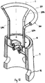
- a protection unit 300 is provided around the charging pole 1, shown in Fig. 2 , for protection of the pole 1 from being hit by vehicles 3.
- the protection unit 300 may comprise an upper ring 310 for surrounding the pole 1, and four legs 320a-d extending along at least a portion of the extension of the pole 1, attaching the ring 310 to the adapter element 11 by means of additional holes, welds or other fastening means (not shown).
- the ring 310 and the four legs 320a-d may be made of any suitable material such as plastic, rubber or metal and may also be made as a solid or a hollow part.
- an advantage of the adapter element 11 is thus that a protection unit 300, or the like, for protection of the charging pole 1 may be attached to the adapter element 11.
- a protection unit 300, or the like, for protection of the charging pole 1 may be attached to the adapter element 11.
- damage to the mounting device 7 is limited to the protection unit 300 and/or adapter element 11.
- only the adapter element 11 will need to be replaced after such an accident and not the whole mounting device 7.
- the mounting device 7 provides lower overall maintenance cost of the infrastructure system, and also higher availability in terms of number of fully functioning charging poles 1, since replacement of the adapter element 11 can be made quickly without digging up, mending or replacing the foundation member 9.
- the system according to the invention may be installed at a site by performing the following method steps:
- a cover member 24 or an adapter element 11; 111; 211 is provided at each respective mounting device 7; 107, depending on if a charging pole 1 is to be initially installed at the mounting device 7; 107 or not.
- the mounting devices 7; 107 are positioned deep enough not to protrude above desired ground level.
- a protection unit 300 may be mounted if there has been an adapter element 11; 111; 211 and a charging pole 1 have been installed.
- a charging pole 1 may be mounted to a mounting device 7 by performing the following method steps:
- Access to the anchoring means 10 may be provided by removing the cover member 24, if present, and/or uncovering the mounting device 7, if covered by paving or the like.
Landscapes
- Engineering & Computer Science (AREA)
- Architecture (AREA)
- Civil Engineering (AREA)
- Structural Engineering (AREA)
- Power Engineering (AREA)
- Transportation (AREA)
- Mechanical Engineering (AREA)
- Charge And Discharge Circuits For Batteries Or The Like (AREA)
- Electric Propulsion And Braking For Vehicles (AREA)
Claims (15)
- Befestigungsvorrichtung für eine Ladesäule, wobei die Ladesäule vorzugsweise angeordnet ist, um ein elektrisch angetriebenes Fahrzeug oder Hybridfahrzeug aufzuladen, wobei die Vorrichtung (7; 107) Folgendes umfasst:(a) ein Fundamentelement (9), das ausgestaltet ist, um unterflur (6) eingebaut zu werden, und(b) ein Verankerungselement (10), mittels dessen die Ladesäule (1) am Fundamentelement (9) befestigt werden kann und das ein lösbares Adapterelement (11; 111; 211) umfasst, das ausgestaltet ist, um die Ladesäule (1) am Fundamentelement (9) anzubringen,dadurch gekennzeichnet, dass das Adapterelement (11; 111; 211) am Fundamentelement (9) unter der Oberkante (9a) des Fundamentelements (9) befestigt ist.
- Vorrichtung nach Anspruch 1, wobei das Fundamentelement (9) hohl ist, und wobei die Befestigung des Adapterelements (11; 111; 211) im Inneren des Fundamentelements (9) angeordnet ist.
- Vorrichtung nach Anspruch 1 oder 2, wobei das Fundamentelement (9) mit ersten Kopplungsmitteln (16, 17; 116, 17; 216, 17) für den Eingriff mit einem zweiten Kopplungsmittel (15; 115, 123; 215) des Adapterelements (11; 111; 211) ausgestattet ist.
- Vorrichtung nach Anspruch 3, wobei die ersten (16, 17; 116, 17; 216, 17) und zweiten (15; 115, 123; 215) Kopplungsmittel einen Vorsprung (5, 15) und eine entsprechende Vertiefung (25, 125) zum gemeinsamen Steuern einer relativen Bewegung zwischen dem Fundamentelement (9) und dem Adapterelement (11; 111; 211) umfassen.
- Vorrichtung nach einem der vorhergehenden Ansprüche, wobei das Adapterelement (11; 111; 211) mit dritten Kopplungsmitteln (26) für den Eingriff mit vierten Kopplungsmitteln der Ladesäule (1) ausgestattet ist.
- Vorrichtung nach Anspruch 5, wobei die dritten (26) und vierten Kopplungsmittel einen Vorsprung und eine entsprechende Vertiefung zum gemeinsamen Steuern einer relativen Bewegung zwischen dem Adapterelement (11; 111; 211) und der Ladesäule (1) umfassen.
- Vorrichtung nach einem der vorhergehenden Ansprüche, wobei eine Durchführung (27) für ein Kabel durch das Fundamentelement (9) bereitgestellt ist.
- Vorrichtung nach einem der vorhergehenden Ansprüche, ferner umfassend eine Schutzeinheit (300), die am Adapterelement (11; 111; 211) befestigt ist.
- Vorrichtung nach Anspruch 8, wobei die Schutzeinheit (300) um die Ladesäule (1) herum angeordnet ist und sich mindestens entlang eines Abschnitts der Ladesäule (1) erstreckt.
- Vorrichtung nach Anspruch 1, die ausgestaltet ist für den Voreinbau der Ladesäule (1) und die ferner ein abnehmbares Abdeckelement (24) umfasst, das ausgestaltet ist, um nach oben offene Räume der Befestigungsvorrichtung (7; 107) abzudecken und um einen Innenraum des Fundamentelements (9) abzudecken, wenn das Adapterelement (11; 111; 211) gelöst ist.
- Vorrichtung nach Anspruch 10, wobei das Abdeckelement (24) ausgestaltet ist, um die offenen Räume vor Regenwasser zu schützen.
- Fundamentsystem für eine Ladesäule, wobei die Ladesäule (1) vorzugsweise angeordnet ist, um elektrisch angetriebene Fahrzeuge oder Hybridfahrzeuge aufzuladen, wobei das System eine Vielzahl von Befestigungsvorrichtungen (7; 107) für Ladesäulen nach einem der vorhergehenden Ansprüche umfasst; wobei jede Befestigungsvorrichtung (7; 107) für Ladesäulen zur elektrischen Versorgung mittels eines oder mehrerer Kabel (5) oder Kabelrohre (8) vorbereitet ist, die im Boden (6) verlegt sind.
- Verfahren für den Einbau mindestens einer Befestigungsvorrichtung für eine Ladesäule nach einem der Ansprüche 1 bis 11, umfassend folgende Schritte:Bereitstellen mindestens einer Vertiefung im Boden (6),Bereitstellen mindestens einer Befestigungsvorrichtung (7; 107) für eine Ladesäule nach einem der Ansprüche 1 bis 11 in der mindestens einen Vertiefung,Bereitstellen von Mitteln zur elektrischen Versorgung (5, 8) der Befestigungsvorrichtungen (7; 107) für Ladesäulen, undWiederherstellen des Bodens (6) an dem Standort, so dass kein Teil der Befestigungsvorrichtungen über Bodenhöhe hinausragt.
- Verfahren für den Einbau einer Ladesäule (1) an einer Befestigungsvorrichtung für eine Ladesäule nach einem der Ansprüche 1 bis 9, umfassend folgende Schritte:Bereitstellen eines Zugangs zu den Verankerungsmitteln (10) der jeweiligen Befestigungsvorrichtung (7; 107),Bereitstellen eines Adapterelements (11; 111; 211) zum Anbringen der Ladesäule (1) an dem Fundamentelement (9), so dass das Adapterelement (11; 111; 211) unter der Oberkante (9a) des Fundamentelements (9) angeordnet ist,Bereitstellen einer elektrischen Versorgung für die Ladesäule (1) mittels eines Kabels (5) oder Kabelrohres (8), das bereits an der Befestigungsvorrichtung (7; 107) bereitgestellt ist, undSichern der Ladesäule (1) an der Befestigungsvorrichtung mittels der Verankerungsmittel (10).
- Verfahren nach Anspruch 13 oder 14, ferner umfassend folgenden Schritt:Ausstatten des Adapterelements (11; 111; 211) mit einer Schutzeinheit (300).
Applications Claiming Priority (2)
| Application Number | Priority Date | Filing Date | Title |
|---|---|---|---|
| SE1150061 | 2011-01-28 | ||
| PCT/EP2012/051370 WO2012101266A2 (en) | 2011-01-28 | 2012-01-27 | Foundation system for charging poles |
Publications (2)
| Publication Number | Publication Date |
|---|---|
| EP2668063A2 EP2668063A2 (de) | 2013-12-04 |
| EP2668063B1 true EP2668063B1 (de) | 2017-01-18 |
Family
ID=45607201
Family Applications (1)
| Application Number | Title | Priority Date | Filing Date |
|---|---|---|---|
| EP12703993.1A Active EP2668063B1 (de) | 2011-01-28 | 2012-01-27 | Fundamentsystem für ladesäulen |
Country Status (3)
| Country | Link |
|---|---|
| US (1) | US9376831B2 (de) |
| EP (1) | EP2668063B1 (de) |
| WO (1) | WO2012101266A2 (de) |
Cited By (2)
| Publication number | Priority date | Publication date | Assignee | Title |
|---|---|---|---|---|
| DE102022001492A1 (de) | 2022-04-28 | 2023-11-02 | Oliver Jauch | Fundamentblock zur Erzeugung eines ortsfesten Ladepunktes für Elektrofahrzeuge sowie Infrastruktur zur Erzeugung zumindest eines solchen Ladepunktes |
| EP4244431B1 (de) * | 2021-05-21 | 2024-01-03 | Unimi Holding AB | Verankerungselement für ladestationsfundament und verfahren zur installation einer ladestation |
Families Citing this family (19)
| Publication number | Priority date | Publication date | Assignee | Title |
|---|---|---|---|---|
| FR3004390B1 (fr) * | 2013-04-16 | 2016-12-09 | Ier Systems | Module de charge pour rechargement electrique d'un vehicule electrique |
| JP6328895B2 (ja) * | 2013-09-10 | 2018-05-23 | トヨタホーム株式会社 | 付加構造物の設置構造 |
| US10224594B2 (en) * | 2016-01-27 | 2019-03-05 | Sabre Industries Inc. | Radio and power pole |
| CN106553561B (zh) * | 2016-11-28 | 2018-10-16 | 深圳市夏瑞科技有限公司 | 一种可便携拆卸安装的新能源汽车充电桩 |
| WO2020245613A1 (en) * | 2019-06-06 | 2020-12-10 | Trevor Palmer | Precast block for housing and routing electrical power cables, an electric vehicle charging station using the block and a manufacturing method |
| CN110789376B (zh) * | 2019-10-23 | 2024-07-23 | 湖南省京湘电力开发有限公司 | 电动车辆充电装置基座 |
| CN110641306B (zh) * | 2019-10-28 | 2024-07-23 | 湖南省京湘电力开发有限公司 | 电动车辆充电装置基座壳体 |
| DE102019007858A1 (de) * | 2019-11-13 | 2021-05-20 | Hauff-Technik Gmbh & Co. Kg | Verwendung eines Anschlussgehäuses |
| WO2021127213A1 (en) | 2019-12-17 | 2021-06-24 | Hubbell Incorporated | Service pole assemblies and fittings for floor mounted service pole integration |
| DE102020117090A1 (de) * | 2020-06-29 | 2021-12-30 | Compleo Charging Solutions Ag | Sockel |
| SE544722C2 (en) | 2020-09-11 | 2022-10-25 | Unimi Holding Ab | A mounting device for a charging station |
| WO2023275521A1 (en) * | 2021-06-28 | 2023-01-05 | Nal Limited | Modular electric vehicle charging foundation system |
| GB2608373B (en) * | 2021-06-28 | 2026-04-22 | Nal Ltd | Modular electric vehicle charging foundation system |
| US20230143736A1 (en) * | 2021-11-08 | 2023-05-11 | GreenCore EV Services LLC | Universal, prefabricated foundation system for electric vehicle charging stations |
| FR3131985B1 (fr) * | 2022-01-17 | 2024-07-26 | Huritaua Faaite | Support en béton comprenant une alvéole d’encastrement d’une portion périphérique d’un socle de coffret, moule de fabrication et procédé de fabrication associés |
| WO2023250496A1 (en) * | 2022-06-24 | 2023-12-28 | Ross Jette | System and method for installing charging dispensers for an electric vehicle |
| GB2620142B (en) * | 2022-06-28 | 2025-09-03 | Yunex Ltd | Electric vehicle charger installation socket |
| GB2620374A (en) * | 2022-06-28 | 2024-01-10 | Yunex Ltd | Electric vehicle charger installation base and method of installation |
| CN118544861B (zh) * | 2024-07-29 | 2024-09-20 | 云南八瑞科技有限公司 | 一种具有防撞着火功能的自断电充电桩 |
Family Cites Families (21)
| Publication number | Priority date | Publication date | Assignee | Title |
|---|---|---|---|---|
| US1001041A (en) * | 1911-03-09 | 1911-08-22 | Edward H Fallows | Locking mechanism for manhole-covers. |
| US2236775A (en) * | 1940-01-11 | 1941-04-01 | Claude H Hunsaker | Equipment foundation of sectional type |
| US3988870A (en) * | 1974-04-25 | 1976-11-02 | Snavely Donald D | Lamp post base |
| DE3380741D1 (en) * | 1983-11-01 | 1989-11-23 | Sven Runo Vilhelm Gebelius | Poleshaped supporting member, and base structure for attachment of same |
| US4716508A (en) | 1985-10-28 | 1987-12-29 | Kramer John F | Outdoor lighting pedestal |
| US4860507A (en) * | 1988-07-15 | 1989-08-29 | Garza Tamez Federico | Structure stabilization system |
| US5263298A (en) * | 1990-01-15 | 1993-11-23 | Ballesteros Angel G | Procedure for making in-situ manholes for underground electric and telephone lines ductwork |
| US5006009A (en) * | 1990-04-27 | 1991-04-09 | Griffin Richard D | Outdoor post assembly |
| IE65270B1 (en) | 1991-03-14 | 1995-10-18 | Square Systems Ltd | Device for supporting a pole |
| US5582720A (en) * | 1995-02-10 | 1996-12-10 | Deming; John P. | Drain closure apparatus |
| US6688806B2 (en) * | 2001-08-21 | 2004-02-10 | Huan-Chang Kuan | Jump-proof manhole-handhole |
| KR100370465B1 (en) * | 2002-08-17 | 2003-02-05 | Hynyang Frame Co Ltd | Structure for supporting guide plate |
| WO2007135119A1 (en) | 2006-05-22 | 2007-11-29 | Square Systems Limited | A device for supporting a pole |
| GB0611332D0 (en) | 2006-06-08 | 2006-07-19 | Elektromotive Ltd | Charging station |
| EP2110478B1 (de) | 2008-04-18 | 2012-09-26 | Square Systems Limited | Vorrichtung zum Halten eines Pfeilers |
| DE102009015605A1 (de) | 2009-04-02 | 2010-10-14 | Siemens Aktiengesellschaft | Verfahren und Schaltungsanordnung zur Kontaktzustandsabfrage |
| DE102009016503A1 (de) | 2009-04-08 | 2010-10-14 | Rwe Ag | Ladesäulensockel für elektrische Ladesäulen |
| DE102009016505A1 (de) * | 2009-04-08 | 2010-10-14 | Rwe Ag | Ladesäule für Elektrofahrzeuge |
| US8111043B2 (en) * | 2009-05-08 | 2012-02-07 | William Gibbens Redmann | Method and apparatus for charging an electric vehicle from a streetlight |
| US8118517B2 (en) * | 2010-03-10 | 2012-02-21 | John Kelley | Manhole cover device |
| EP2551144B1 (de) * | 2010-03-22 | 2016-03-16 | Ingeteam Power Technology, S.A. | Estación de recarga de vehículos eléctricos y sistema de recarga de dichos vehículos |
-
2012
- 2012-01-27 WO PCT/EP2012/051370 patent/WO2012101266A2/en not_active Ceased
- 2012-01-27 EP EP12703993.1A patent/EP2668063B1/de active Active
- 2012-01-27 US US13/982,028 patent/US9376831B2/en active Active
Non-Patent Citations (1)
| Title |
|---|
| None * |
Cited By (3)
| Publication number | Priority date | Publication date | Assignee | Title |
|---|---|---|---|---|
| EP4244431B1 (de) * | 2021-05-21 | 2024-01-03 | Unimi Holding AB | Verankerungselement für ladestationsfundament und verfahren zur installation einer ladestation |
| EP4322348B1 (de) * | 2021-05-21 | 2026-02-04 | Unimi Holding AB | Verankerungselement für ladestationsfundament und verfahren zur installation einer ladestation |
| DE102022001492A1 (de) | 2022-04-28 | 2023-11-02 | Oliver Jauch | Fundamentblock zur Erzeugung eines ortsfesten Ladepunktes für Elektrofahrzeuge sowie Infrastruktur zur Erzeugung zumindest eines solchen Ladepunktes |
Also Published As
| Publication number | Publication date |
|---|---|
| WO2012101266A2 (en) | 2012-08-02 |
| US20130309022A1 (en) | 2013-11-21 |
| EP2668063A2 (de) | 2013-12-04 |
| US9376831B2 (en) | 2016-06-28 |
| WO2012101266A3 (en) | 2012-09-20 |
Similar Documents
| Publication | Publication Date | Title |
|---|---|---|
| US9376831B2 (en) | Foundation system for charging poles | |
| JP7348674B2 (ja) | 電気車両充電ステーション | |
| US9561731B2 (en) | Structural bollard assembly for electric vehicle infrastructure | |
| US20230331104A1 (en) | Kerbside Vehicle Charger | |
| EP2539967B1 (de) | Einlassbaugruppe | |
| CA3067438C (en) | Charging station | |
| US20230365014A1 (en) | Charging station foundation | |
| EP2323237A2 (de) | Elektrofahrzeugladestation | |
| KR101358985B1 (ko) | 안정성 및 시공성이 우수한 지주 정착 구조물 및 그 시공 방법 | |
| WO2018119050A1 (en) | Structural bollard assembly for electric vehicle infrastructure | |
| CN114228550A (zh) | 用于电能的蓄能器装置、充电系统和安装蓄能器装置或充电系统的方法 | |
| KR100947852B1 (ko) | 가로등 등주와 기초의 결합구조 | |
| US20220228324A1 (en) | Curb power source | |
| EP4360177B1 (de) | Ladeanordnung für elektrofahrzeug | |
| EP4322348B1 (de) | Verankerungselement für ladestationsfundament und verfahren zur installation einer ladestation | |
| CN117999188A (zh) | 电动车辆充电站及其接口装置 | |
| CA3217127A1 (en) | Modular charging system | |
| CN213734639U (zh) | 一种智能停车场用充电桩防护组件 | |
| CN111762041A (zh) | 一种预制模块化电动车充电、停车系统 | |
| JP3147534U (ja) | 電源供給型パーキングブロック | |
| KR20150024195A (ko) | 배수홀을 포함하는 헌치부재 및 이를 활용한 교량구조물 | |
| WO2025125726A1 (en) | A charging station and an extendable charging system | |
| SE533511C2 (sv) | Laddstolpe för laddning av elfordon | |
| JP4528269B2 (ja) | 電柱 | |
| CN101591919A (zh) | 一种接线井井盖与井体的连接结构 |
Legal Events
| Date | Code | Title | Description |
|---|---|---|---|
| PUAI | Public reference made under article 153(3) epc to a published international application that has entered the european phase |
Free format text: ORIGINAL CODE: 0009012 |
|
| 17P | Request for examination filed |
Effective date: 20130816 |
|
| AK | Designated contracting states |
Kind code of ref document: A2 Designated state(s): AL AT BE BG CH CY CZ DE DK EE ES FI FR GB GR HR HU IE IS IT LI LT LU LV MC MK MT NL NO PL PT RO RS SE SI SK SM TR |
|
| DAX | Request for extension of the european patent (deleted) | ||
| RIN1 | Information on inventor provided before grant (corrected) |
Inventor name: HOEKFELT, MATHIAS |
|
| GRAP | Despatch of communication of intention to grant a patent |
Free format text: ORIGINAL CODE: EPIDOSNIGR1 |
|
| INTG | Intention to grant announced |
Effective date: 20160811 |
|
| GRAS | Grant fee paid |
Free format text: ORIGINAL CODE: EPIDOSNIGR3 |
|
| GRAA | (expected) grant |
Free format text: ORIGINAL CODE: 0009210 |
|
| AK | Designated contracting states |
Kind code of ref document: B1 Designated state(s): AL AT BE BG CH CY CZ DE DK EE ES FI FR GB GR HR HU IE IS IT LI LT LU LV MC MK MT NL NO PL PT RO RS SE SI SK SM TR |
|
| REG | Reference to a national code |
Ref country code: GB Ref legal event code: FG4D |
|
| REG | Reference to a national code |
Ref country code: CH Ref legal event code: EP |
|
| REG | Reference to a national code |
Ref country code: AT Ref legal event code: REF Ref document number: 862697 Country of ref document: AT Kind code of ref document: T Effective date: 20170215 |
|
| REG | Reference to a national code |
Ref country code: IE Ref legal event code: FG4D |
|
| REG | Reference to a national code |
Ref country code: DE Ref legal event code: R096 Ref document number: 602012027951 Country of ref document: DE |
|
| REG | Reference to a national code |
Ref country code: FR Ref legal event code: PLFP Year of fee payment: 6 |
|
| REG | Reference to a national code |
Ref country code: SE Ref legal event code: TRGR |
|
| REG | Reference to a national code |
Ref country code: NL Ref legal event code: MP Effective date: 20170118 |
|
| REG | Reference to a national code |
Ref country code: LT Ref legal event code: MG4D |
|
| PG25 | Lapsed in a contracting state [announced via postgrant information from national office to epo] |
Ref country code: BE Free format text: LAPSE BECAUSE OF NON-PAYMENT OF DUE FEES Effective date: 20170131 |
|
| REG | Reference to a national code |
Ref country code: NO Ref legal event code: T2 Effective date: 20170118 |
|
| REG | Reference to a national code |
Ref country code: AT Ref legal event code: MK05 Ref document number: 862697 Country of ref document: AT Kind code of ref document: T Effective date: 20170118 |
|
| PG25 | Lapsed in a contracting state [announced via postgrant information from national office to epo] |
Ref country code: NL Free format text: LAPSE BECAUSE OF FAILURE TO SUBMIT A TRANSLATION OF THE DESCRIPTION OR TO PAY THE FEE WITHIN THE PRESCRIBED TIME-LIMIT Effective date: 20170118 |
|
| PG25 | Lapsed in a contracting state [announced via postgrant information from national office to epo] |
Ref country code: HR Free format text: LAPSE BECAUSE OF FAILURE TO SUBMIT A TRANSLATION OF THE DESCRIPTION OR TO PAY THE FEE WITHIN THE PRESCRIBED TIME-LIMIT Effective date: 20170118 Ref country code: LT Free format text: LAPSE BECAUSE OF FAILURE TO SUBMIT A TRANSLATION OF THE DESCRIPTION OR TO PAY THE FEE WITHIN THE PRESCRIBED TIME-LIMIT Effective date: 20170118 Ref country code: IS Free format text: LAPSE BECAUSE OF FAILURE TO SUBMIT A TRANSLATION OF THE DESCRIPTION OR TO PAY THE FEE WITHIN THE PRESCRIBED TIME-LIMIT Effective date: 20170518 Ref country code: GR Free format text: LAPSE BECAUSE OF FAILURE TO SUBMIT A TRANSLATION OF THE DESCRIPTION OR TO PAY THE FEE WITHIN THE PRESCRIBED TIME-LIMIT Effective date: 20170419 |
|
| PG25 | Lapsed in a contracting state [announced via postgrant information from national office to epo] |
Ref country code: ES Free format text: LAPSE BECAUSE OF FAILURE TO SUBMIT A TRANSLATION OF THE DESCRIPTION OR TO PAY THE FEE WITHIN THE PRESCRIBED TIME-LIMIT Effective date: 20170118 Ref country code: RS Free format text: LAPSE BECAUSE OF FAILURE TO SUBMIT A TRANSLATION OF THE DESCRIPTION OR TO PAY THE FEE WITHIN THE PRESCRIBED TIME-LIMIT Effective date: 20170118 Ref country code: LV Free format text: LAPSE BECAUSE OF FAILURE TO SUBMIT A TRANSLATION OF THE DESCRIPTION OR TO PAY THE FEE WITHIN THE PRESCRIBED TIME-LIMIT Effective date: 20170118 Ref country code: PT Free format text: LAPSE BECAUSE OF FAILURE TO SUBMIT A TRANSLATION OF THE DESCRIPTION OR TO PAY THE FEE WITHIN THE PRESCRIBED TIME-LIMIT Effective date: 20170518 Ref country code: PL Free format text: LAPSE BECAUSE OF FAILURE TO SUBMIT A TRANSLATION OF THE DESCRIPTION OR TO PAY THE FEE WITHIN THE PRESCRIBED TIME-LIMIT Effective date: 20170118 Ref country code: BG Free format text: LAPSE BECAUSE OF FAILURE TO SUBMIT A TRANSLATION OF THE DESCRIPTION OR TO PAY THE FEE WITHIN THE PRESCRIBED TIME-LIMIT Effective date: 20170418 Ref country code: AT Free format text: LAPSE BECAUSE OF FAILURE TO SUBMIT A TRANSLATION OF THE DESCRIPTION OR TO PAY THE FEE WITHIN THE PRESCRIBED TIME-LIMIT Effective date: 20170118 |
|
| REG | Reference to a national code |
Ref country code: CH Ref legal event code: PL |
|
| REG | Reference to a national code |
Ref country code: DE Ref legal event code: R097 Ref document number: 602012027951 Country of ref document: DE |
|
| PG25 | Lapsed in a contracting state [announced via postgrant information from national office to epo] |
Ref country code: SK Free format text: LAPSE BECAUSE OF FAILURE TO SUBMIT A TRANSLATION OF THE DESCRIPTION OR TO PAY THE FEE WITHIN THE PRESCRIBED TIME-LIMIT Effective date: 20170118 Ref country code: CH Free format text: LAPSE BECAUSE OF NON-PAYMENT OF DUE FEES Effective date: 20170131 Ref country code: IT Free format text: LAPSE BECAUSE OF FAILURE TO SUBMIT A TRANSLATION OF THE DESCRIPTION OR TO PAY THE FEE WITHIN THE PRESCRIBED TIME-LIMIT Effective date: 20170118 Ref country code: RO Free format text: LAPSE BECAUSE OF FAILURE TO SUBMIT A TRANSLATION OF THE DESCRIPTION OR TO PAY THE FEE WITHIN THE PRESCRIBED TIME-LIMIT Effective date: 20170118 Ref country code: CZ Free format text: LAPSE BECAUSE OF FAILURE TO SUBMIT A TRANSLATION OF THE DESCRIPTION OR TO PAY THE FEE WITHIN THE PRESCRIBED TIME-LIMIT Effective date: 20170118 Ref country code: LI Free format text: LAPSE BECAUSE OF NON-PAYMENT OF DUE FEES Effective date: 20170131 Ref country code: EE Free format text: LAPSE BECAUSE OF FAILURE TO SUBMIT A TRANSLATION OF THE DESCRIPTION OR TO PAY THE FEE WITHIN THE PRESCRIBED TIME-LIMIT Effective date: 20170118 |
|
| REG | Reference to a national code |
Ref country code: IE Ref legal event code: MM4A |
|
| PLBE | No opposition filed within time limit |
Free format text: ORIGINAL CODE: 0009261 |
|
| STAA | Information on the status of an ep patent application or granted ep patent |
Free format text: STATUS: NO OPPOSITION FILED WITHIN TIME LIMIT |
|
| PG25 | Lapsed in a contracting state [announced via postgrant information from national office to epo] |
Ref country code: LU Free format text: LAPSE BECAUSE OF NON-PAYMENT OF DUE FEES Effective date: 20170127 Ref country code: MC Free format text: LAPSE BECAUSE OF FAILURE TO SUBMIT A TRANSLATION OF THE DESCRIPTION OR TO PAY THE FEE WITHIN THE PRESCRIBED TIME-LIMIT Effective date: 20170118 Ref country code: DK Free format text: LAPSE BECAUSE OF FAILURE TO SUBMIT A TRANSLATION OF THE DESCRIPTION OR TO PAY THE FEE WITHIN THE PRESCRIBED TIME-LIMIT Effective date: 20170118 Ref country code: SM Free format text: LAPSE BECAUSE OF FAILURE TO SUBMIT A TRANSLATION OF THE DESCRIPTION OR TO PAY THE FEE WITHIN THE PRESCRIBED TIME-LIMIT Effective date: 20170118 |
|
| 26N | No opposition filed |
Effective date: 20171019 |
|
| REG | Reference to a national code |
Ref country code: FR Ref legal event code: PLFP Year of fee payment: 7 |
|
| REG | Reference to a national code |
Ref country code: BE Ref legal event code: MM Effective date: 20170131 |
|
| PG25 | Lapsed in a contracting state [announced via postgrant information from national office to epo] |
Ref country code: IE Free format text: LAPSE BECAUSE OF NON-PAYMENT OF DUE FEES Effective date: 20170127 Ref country code: SI Free format text: LAPSE BECAUSE OF FAILURE TO SUBMIT A TRANSLATION OF THE DESCRIPTION OR TO PAY THE FEE WITHIN THE PRESCRIBED TIME-LIMIT Effective date: 20170118 |
|
| PG25 | Lapsed in a contracting state [announced via postgrant information from national office to epo] |
Ref country code: MT Free format text: LAPSE BECAUSE OF NON-PAYMENT OF DUE FEES Effective date: 20170127 |
|
| REG | Reference to a national code |
Ref country code: DE Ref legal event code: R079 Ref document number: 602012027951 Country of ref document: DE Free format text: PREVIOUS MAIN CLASS: B60L0011180000 Ipc: B60L0050500000 |
|
| PG25 | Lapsed in a contracting state [announced via postgrant information from national office to epo] |
Ref country code: HU Free format text: LAPSE BECAUSE OF FAILURE TO SUBMIT A TRANSLATION OF THE DESCRIPTION OR TO PAY THE FEE WITHIN THE PRESCRIBED TIME-LIMIT; INVALID AB INITIO Effective date: 20120127 |
|
| PG25 | Lapsed in a contracting state [announced via postgrant information from national office to epo] |
Ref country code: CY Free format text: LAPSE BECAUSE OF NON-PAYMENT OF DUE FEES Effective date: 20170118 |
|
| PG25 | Lapsed in a contracting state [announced via postgrant information from national office to epo] |
Ref country code: MK Free format text: LAPSE BECAUSE OF FAILURE TO SUBMIT A TRANSLATION OF THE DESCRIPTION OR TO PAY THE FEE WITHIN THE PRESCRIBED TIME-LIMIT Effective date: 20170118 |
|
| REG | Reference to a national code |
Ref country code: DE Ref legal event code: R081 Ref document number: 602012027951 Country of ref document: DE Owner name: UNIMI HOLDING AB, SE Free format text: FORMER OWNER: UNIMI SOLUTIONS AB, TAEBY, SE |
|
| PG25 | Lapsed in a contracting state [announced via postgrant information from national office to epo] |
Ref country code: TR Free format text: LAPSE BECAUSE OF FAILURE TO SUBMIT A TRANSLATION OF THE DESCRIPTION OR TO PAY THE FEE WITHIN THE PRESCRIBED TIME-LIMIT Effective date: 20170118 |
|
| REG | Reference to a national code |
Ref country code: GB Ref legal event code: 732E Free format text: REGISTERED BETWEEN 20200326 AND 20200401 |
|
| REG | Reference to a national code |
Ref country code: NO Ref legal event code: CHAD Owner name: UNIMI HOLDING AB, SE |
|
| REG | Reference to a national code |
Ref country code: FI Ref legal event code: PCE Owner name: UNIMI HOLDING AB |
|
| PG25 | Lapsed in a contracting state [announced via postgrant information from national office to epo] |
Ref country code: AL Free format text: LAPSE BECAUSE OF FAILURE TO SUBMIT A TRANSLATION OF THE DESCRIPTION OR TO PAY THE FEE WITHIN THE PRESCRIBED TIME-LIMIT Effective date: 20170118 |
|
| REG | Reference to a national code |
Ref country code: DE Ref legal event code: R084 Ref document number: 602012027951 Country of ref document: DE |
|
| REG | Reference to a national code |
Ref country code: GB Ref legal event code: 746 Effective date: 20240301 |
|
| P01 | Opt-out of the competence of the unified patent court (upc) registered |
Free format text: CASE NUMBER: APP_4609/2025 Effective date: 20250128 |
|
| PGFP | Annual fee paid to national office [announced via postgrant information from national office to epo] |
Ref country code: DE Payment date: 20250121 Year of fee payment: 14 |
|
| PGFP | Annual fee paid to national office [announced via postgrant information from national office to epo] |
Ref country code: FI Payment date: 20250124 Year of fee payment: 14 |
|
| PGFP | Annual fee paid to national office [announced via postgrant information from national office to epo] |
Ref country code: NO Payment date: 20250127 Year of fee payment: 14 |
|
| PGFP | Annual fee paid to national office [announced via postgrant information from national office to epo] |
Ref country code: GB Payment date: 20250120 Year of fee payment: 14 |
|
| PGFP | Annual fee paid to national office [announced via postgrant information from national office to epo] |
Ref country code: SE Payment date: 20260120 Year of fee payment: 15 |
|
| PGFP | Annual fee paid to national office [announced via postgrant information from national office to epo] |
Ref country code: FR Payment date: 20260115 Year of fee payment: 15 |