EP2669191A2 - Slatstützanordnung - Google Patents
Slatstützanordnung Download PDFInfo
- Publication number
- EP2669191A2 EP2669191A2 EP13169028.1A EP13169028A EP2669191A2 EP 2669191 A2 EP2669191 A2 EP 2669191A2 EP 13169028 A EP13169028 A EP 13169028A EP 2669191 A2 EP2669191 A2 EP 2669191A2
- Authority
- EP
- European Patent Office
- Prior art keywords
- slat
- support arm
- shaft
- slat support
- support assembly
- Prior art date
- Legal status (The legal status is an assumption and is not a legal conclusion. Google has not performed a legal analysis and makes no representation as to the accuracy of the status listed.)
- Granted
Links
Images




Classifications
-
- B—PERFORMING OPERATIONS; TRANSPORTING
- B64—AIRCRAFT; AVIATION; COSMONAUTICS
- B64C—AEROPLANES; HELICOPTERS
- B64C9/00—Adjustable control surfaces or members, e.g. rudders
- B64C9/14—Adjustable control surfaces or members, e.g. rudders forming slots
-
- B—PERFORMING OPERATIONS; TRANSPORTING
- B64—AIRCRAFT; AVIATION; COSMONAUTICS
- B64C—AEROPLANES; HELICOPTERS
- B64C9/00—Adjustable control surfaces or members, e.g. rudders
- B64C9/14—Adjustable control surfaces or members, e.g. rudders forming slots
- B64C9/22—Adjustable control surfaces or members, e.g. rudders forming slots at the front of the wing
-
- Y—GENERAL TAGGING OF NEW TECHNOLOGICAL DEVELOPMENTS; GENERAL TAGGING OF CROSS-SECTIONAL TECHNOLOGIES SPANNING OVER SEVERAL SECTIONS OF THE IPC; TECHNICAL SUBJECTS COVERED BY FORMER USPC CROSS-REFERENCE ART COLLECTIONS [XRACs] AND DIGESTS
- Y02—TECHNOLOGIES OR APPLICATIONS FOR MITIGATION OR ADAPTATION AGAINST CLIMATE CHANGE
- Y02T—CLIMATE CHANGE MITIGATION TECHNOLOGIES RELATED TO TRANSPORTATION
- Y02T50/00—Aeronautics or air transport
- Y02T50/40—Weight reduction
Definitions
- the invention relates to a slat support assembly for supporting a slat on the leading edge of an aircraft wing.
- the invention also relates to a joint for coupling a slat to one end of a slat support arm and an aircraft wing comprising at least one slat attached to a leading edge of the wing using the support assembly of the invention.
- Aircraft need to produce varying levels of lift for take-off, landing and cruise.
- a combination of wing leading and trailing edge devices are used to control the wing coefficient of lift.
- the leading edge device is known as a slat.
- the slats usually follow an arcuate or curved path between their stowed and deployed positions. By varying the extent to which the slat is deployed along said path, the lift provided by the wing can be controlled.
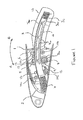
- FIG. 1 An assembly is required to support and guide movement of a slat between stowed and deployed positions and a typical arrangement, showing a cross-section through part of a wing 1 and a slat 2 in its stowed position is illustrated in Figure 1 .
- the slat 2 is provided with an arcuate support arm or slat track 3 one end 4 of which is attached to the rear of the slat 2 by a fixed joint and extends into the wing 1.
- the support arm 3 penetrates a machined rib 5 and a wing spar 6 forming the wing structure.
- the support arm 3 defines an arc having an axis and is mounted within the wing so that it can rotate about that axis (in the direction indicated by arrows "A" and "B” in Figure 1 ) to deploy and retract the slat 2 attached to one end of the support arm 3, with the axis extending along the wing.
- a toothed slat rack 7 having an arcuate shape corresponding to the arcuate shape of the support arm 3 is mounted within a recess 3a on the support arm 3 and a correspondingly toothed drive pinion 8 is in engagement with the teeth 7a on the slat rack 7 so that when the drive pinion 8 rotates, the teeth 8a on the drive pinion 8 and the teeth 7a on the rack 7 cooperate to pivot or drive the slat rack 7 and the slat 2 attached thereto, into a deployed position, i.e. in the direction of arrow "A" in Figure 1 .
- the support arm 3 rotates through an angle of 27 degrees between its fully stowed and fully deployed positions. Rotation of the pinion 8 in the opposite direction also drives the support arm 3, in the direction of arrow "B", back into its stowed position, as shown in Figure 1 .
- the drive pinion 8 is mounted on a shaft 9 that extends along, and within, the leading edge of the wing 1.
- Several gears 8 may be rotatably mounted on the shaft 8, one for driving each slat 2 so that when the shaft 9 is rotated by a slat deployment motor close to the inboard end of the wing 1, all the support arms 3 are deployed together so that the slat 2, or a plurality of slats, is deployed uniformly.
- the support arm 3 has a generally square cross-sectional profile such that its upper and lower surfaces 3b, 3c each define a portion of a curved surface of a cylinder each having its axis coaxial with the axis of rotation of the support arm 3.
- the support arm 3 is supported between front upper and lower roller bearings 10a, 10b, and rear upper and lower roller bearings 11a,11b spaced from the front upper and lower roller bearings 10a.
- the axis of rotation of each bearing 10a, 10b, 11a, 11b is parallel to the axis of rotation of each of the other bearings 10a, 10b, 11a, 11b and to the axis about which the support arm 3 rotates in the direction of arrows "A" and "B" between its stowed and deployed positions.
- the upper bearings 10a, 11a lie in contact with the upper surface 3b of the support arm 3 and the lower bearings 10b, 11b lie in contact with the lower surface 3c so that they support the support arm 3 and guide it during deployment and retraction.
- the bearings 10a, 10b, 11a, 11b resist vertical loads applied to the slat 2 during flight both in stowed and deployed positions and also guide movement of the support arm 2 during slat deployment and retraction.
- bearings 10a, 10b, 11a, 11b resist loads that are applied in the vertical direction only.
- vertical loads are meant loads that act in a direction extending in the plane of the drawing or, in a direction acting at right-angles to the axis about which the support arm 3 rotates in the direction of arrows "A" and "B" between its stowed and deployed positions.
- side-loads loads that act in a direction other than in a direction that extends in the plane of the drawing or, in other words, those loads that act in a direction other than at right-angles to the axis about which the support arm 3 rotates in the direction of arrows "A" and "B" between its stowed and deployed positions.
- the support arm 3 is also supported by side bearings 12 disposed on either side of the support arm 3 as opposed to the vertical load bearings 10, 11 mounted above and below the support arm 3.
- These side-load bearings 12 are generally roller bearings, however it will be appreciated that they may just comprise bearing surfaces, pads or cushions against which the side walls of the support arm 3 may bear when side loads are applied to the slat 2.
- the primary and secondary support arms 15,16 are fixedly mounted to the slat 2 by fixed joints 19.
- the primary support arm 15 is supported by opposing front side-load bearings 17 disposed on either side of the support arm 15, opposing rear side-load bearings 18 disposed on either side of the support arm 15, and upper and lower bearings (not shown).
- the rear side-load bearings 18 are spaced from the front side bearings 17, and each of the primary support arm side-load bearings 17, 18 abut against the primary 15 support arm to a close clearance tolerance to restrict lateral movement of the master support arm 15.
- the secondary support arm 16 is supported by opposing front side-load bearings 17a disposed on either side of the secondary support arm 16, opposing rear side-load bearings 18a disposed on either side of the secondary support arm 16 and upper and lower bearings (not shown).
- the rear side-load bearings 18a are spaced from the front side bearings 17a.
- the rear side-load bearings 18a of the secondary support arm 16 abut against the secondary support arm 16 to a close clearance tolerance to restrict lateral movement of the secondary support arm 16 proximate thereto.
- the front side-load bearings 17a of the secondary support arm 16 are spaced away from the secondary support arm 16 so that there is a clearance between the secondary support arm 16 and its front side-load bearings 17a. As a consequence of this, the secondary support arm is capable of sliding laterally to compensate for wing bending.
- Embodiments of the invention seek to provide an aircraft slat support assembly that overcomes or substantially alleviates the problems referred to above.
- a slat support assembly comprising a slat support arm which is movable to deploy a slat from a leading edge of an aircraft wing about an axis of rotation of the arm and a slat mount on a slat which is coupled to one end of said slat support arm by a joint, wherein the joint is configured to allow the slat mount to slide in a direction of the axis of rotation of the arm.
- the joint comprises a bearing element mounted to the slat mount, the bearing element being slidably received in a bearing sleeve on the slat support arm.
- the bearing element may be configured to slide in a linear direction in the bearing sleeve.
- the bearing element comprises a shaft which is slidable in the bearing sleeve in a direction along a longitudinal axis of the shaft.
- the bearing sleeve comprises opposing bushes on the slat support arm and ends of the shaft are slidably received in the bushes, and the shaft extends between the opposing bushes.
- the slat support assembly may further comprise a yoke formed at the one end of the slat support arm with two spaced yoke members, wherein the opposing bushes are formed in the yoke members.
- the slat mount is disposed between the yoke members.
- the slat mount is mountable to the shaft of the bearing element between the ends of the shaft.
- the ends of the shaft form cylindrical bearing journal surfaces which mate with corresponding bearing seats of the bushes.
- the longitudinal axis of the shaft extends parallel to the axis of rotation of the arm.
- Each bush may have an end stop at an end thereof, and the ends of the shaft may be capable of abutting the end stops to restrict the range of motion of the shaft.
- the length of the shaft may be shorter than the distance between the end stops of the opposing bushes so that the shaft is slidable in the bushes between the two end stops.
- an outlet is formed through each end stop.
- the slat mount is pivotally mounted to the shaft.
- the slat support assembly may further comprise a collar on the slat mounting slat mount which locates around and mates with the shaft.
- the shaft further comprises a part-spherical section disposed between each end of the shaft and the collar locates around and mates with the part-spherical section of the shaft.
- the range of motion of the shaft is configured to prevent the slat mount abutting the yoke members.
- the slat support assembly further comprises a link arm extending between the slat support arm and the slat to prevent rotation of the slat about the longitudinal axis of the shaft.
- the link arm may be pivotally mounted to the slat support arm and the slat by spherical bearings.
- a pin extends through the shaft along the longitudinal axis of the shaft to strengthen the shaft.
- the pin is fixedly mounted at each end to the bearing seat and the shaft is slidable along the pin.
- the pin may be fixedly mounted to the end stops.
- the slat support assembly may further comprise a plurality of bearings mountable within a wing, each bearing being in rolling contact with an associated bearing surface on the slat support arm to support the slat support arm and guide it during deployment and retraction of the slat, wherein at least some of the bearing surfaces and associated bearings are configured so that each bearing counteracts load applied to the slat support arm in more than one direction.
- the slat support arm has a pair of adjacent upper bearing surfaces, each upper bearing surface being arranged at an angle relative to its adjacent upper bearing surface such that a bearing associated with one upper bearing surface does not share a common axis with the bearing associated with the other upper bearing surface.
- the slat support assembly comprises a groove in the slat support arm and a slat rack mounted to the slat support arm in the groove for cooperation with a drive pinion configured to rotate the slat track about its axis for deployment and retraction of the slat.
- a joint for coupling a slat to one end of a slat support arm which is movable to deploy said slat from a leading edge of an aircraft wing about an axis of rotation of said slat support arm comprising a bearing element mountable to a slat and a bearing element sleeve mountable to a slat support arm, wherein the bearing element is configured to slide in the sleeve so that said slat is slidable relative to said slat support arm in the direction of the axis of rotation of the arm.
- an aircraft wing having a slat and a slat support assembly according to the invention.
- the slat support assembly is a secondary slat support assembly which mounts a secondary slat mount of a slat to a secondary slat support assembly
- the aircraft wing further comprises a primary slat support assembly configured to fixedly mount a primary slat mount of said slat to a primary slat support arm which is configured to prevent the primary slat mount from sliding in the direction of the axis of rotation of the primary slat support arm.
- Figures 1 and 2 represent prior art views of a portion of a leading edge of a wing and slat and have already been described above.
- a slat support assembly 20 comprising a slat support arm or slat track 22 coupled to a slat 23.
- a front end 24 of the support arm 22 is attached to the slat 23, and a slat track support assembly (not shown) supports and mounts the support arm 22 to a wing, and enables the slat to be moved between its stowed and deployed positions.
- the slat track support assembly is not shown in this Figure, however it is described above in respect to the prior art, and so a further detailed description of the slat track support assembly will not be given herein.
- the slat support arm 22 is arcuate and rotates about its theoretical centre or axis (not shown in the Figures) to urge the slat 23 attached to the slat support arm 22 to rotate in the direction of arrows "A" and "B", between its stowed and deployed positions.
- the axis about which the slat support arm 22 rotates extends longitudinally along the width of the slat 23, extending in a direction out of the sheet towards the viewer, as is conventional.
- the slat 23 comprises an outer face 25 and an inner face 26.
- First and second slat mounts or mounting lugs 27, 28 extend from the inner face 26 for attaching the slat 23 to the slat support arm 22, as will be explained hereinafter.
- first and second slat mounts 27,28 are shown, it will be appreciated that two or more slat support arms 22 may be attached to and spaced along the slat 23 by a plurality of corresponding slat mounts 27,28.
- the slat support arm 22 is coupled to the slat 23 at the front end 24 of the support arm 22 by a first joint 29 which couples the front end 24 of the support arm 22 to the first slat mount 27 extending from the slat 23, as will be explained hereinafter.
- a link arm 30 is coupled to the slat support arm 22 by a second joint 32, which is spaced from the first joint 29 along the slat support arm 22.
- the other end of the link arm 30 distal to the slat support arm 22 is coupled to the slat 23 by a third joint 33 which attaches said end of the link arm 26 to the second slat mount 28 extending from the slat 23.
- a triangular truss is defined by the link arm 30, a section of the slat support arm 22 between the first and second joints 29, 32 and a section of the slat 23 between the first and second slat mounts 27,28.
- the truss prevents the slat 23 from rotating about the first joint 29 on an axis extending parallel to the theoretical axis of the slat support arm 22 about which the slat support arm 22 rotates between its stowed and deployed positions.
- the front end 24 of the slat support arm 22 is shown in Figure 4 with the slat 23 removed for clarity.
- the link arm 30 comprises two parallel link members 34 which are spaced from each other and are disposed on, and mounted to, opposing sides of the slat support arm 22.
- the second slat mount 28 extends between the two parallel link members 34 of the link arm 30 at a distal end of the link arm 30 to the support arm 22.
- a yoke 35 extends from the front end 24 of the slat support arm 22.
- the yoke 35 comprises a pair of spaced yoke members 36 which extend parallel to each other and define a slat mount receiving space 41 therebetween.
- Each yoke member 36 has an inner surface 37 facing the other yoke member, and an outer surface 38.
- a bush receiving aperture 40 is formed through each yoke member 36 between its inner and outer surfaces 37, 38 and a corresponding plain bearing or bush 42 is received in each aperture 40, as will be explained hereinafter.
- the bushes are fixedly mounted in each yoke member 36, it will be appreciated that in an alternative embodiment the bushes may be formed together with the yoke members.
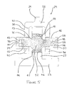
- the first slat mount 27 extending from the inner face 26 of the slat 23 comprises opposing side faces 44, as shown in Figure 5 .
- a collar receiving aperture 46 is formed to extend between the side faces 44 to receive a bearing collar 47 therein.
- the first joint 29 is illustrated in cross-section coupling the front end 24 of the support arm 22 to the first slat mount 27 extending from the slat 23.
- the first slat mount 27 of the slat 23 is disposed in the slat mount receiving space 41 defined between the yoke members 36 of the slat support arm 22.
- the first joint 29 further comprises the bushes 42 defining a bearing sleeve 43 fixedly mounted in the respective bush receiving apertures 40 formed through each yoke member 36, the bearing collar 47 fixedly mounted in the first slat mount 27, and a bearing element 48 which is slidably received in the bushes 42 and bearing collar 47, as will be explained in detail hereinafter.
- the bearing element 48 comprises a shaft 50 which is received in the bearing sleeve 43 such that it extends between the bushes 42 in the opposing yoke members 36 and has a central part-spherical region 52 that forms a male bearing seat or surface 53.
- the collar 47 in the first slat mount 27 defines an inner or female part spherical bearing surface 54 that locates around, and mates with, the part-spherical bearing surface 53 formed on the shaft 50 of the bearing element 48 so that the bearing element 48, and therefore the slat support arm 22 can rotate relative to the slat 23 in all directions.
- End portions 54 of the shaft 50 extending from the central part-spherical region 52 of the bearing element 48 are received in the bushes 42.
- the end portions 54 extend along an axis defining the longitudinal axis of the shaft 50 and each has a shaft end face 55.
- the end portions 54 are cylindrical and their circumferential outer surfaces 56 form a male bearing surface.
- Each bush 42 forms a bearing seat 57 in which the end portions 54 of the shaft 50 are received.
- An inner end of each bush 42 lies flush with the inner surface 37 of the corresponding yoke member 36, whereas an outer end of each bush 42 extends from the outer surface 38 of the corresponding yoke member 36 so that each end portion 54 of the shaft 50 is fully received in the bushes 42 of the bearing sleeve 43.
- Each bush 42 has an end stop 58 at an outer end against which an end face 55 of the respective shaft end portion 52 may abut when the bearing element 48 slides in the bearing sleeve 43 toward the end stop 58, as will be explained hereinafter.
- each bush 42 forms a female bearing surface that locates around, and mates with, the male bearing surfaces of the shaft end portions 54 so that the bearing element 48 slides linearly in the bearing sleeve 43 along its longitudinal axis, as will become apparent hereinafter.
- An outlet 59 is formed through each end stop 58 to allow the flow of air therethrough to prevent the bearing element 48 acting as a piston and causing a pressure differential in the space defined between the bushes 42 and the shaft 50 when the bearing element 48 slides in a linear motion along its longitudinal axis towards one of the end stops 58.
- the length of the bearing element 48 between the opposing shaft end faces 54 is less than the distance between the end stops 57 of the opposing bushes 42 of the bearing sleeve 43. Therefore, when the slat 23 is in a neutral position, that is the first slat mount 27 is not urged to move laterally and is disposed equidistant from each yoke member, the end faces 54 of the shaft 50 are spaced from the end stops 57 at opposing ends of the bearing sleeve 43, and a gap is formed therebetween.
- the second and third joints 32, 33 mounting the link arm 34 to the slat support arm 22 and second slat mount 28 of the slat 23 respectively comprise conventional spherical bearings, and so a detailed description will be omitted herein.
- the slat 23 is mounted to the wing (not shown) by two slat support assemblies 29,62. Each support arm of the slat support assemblies is mounted to the wing by a corresponding slat track support assembly 60 so that the slat 23 is rotatable between its stowed and deployed positions.
- the slat 23 is mounted by means of a primary slat support assembly 62 and a secondary slat support assembly 20. Although only one secondary slat track assembly is shown in the exemplary Figures, it will be appreciated that a slat may be mounted by a plurality of secondary slat support assemblies.
- the above described embodiment of the slat support assembly 20 is a secondary slat support assembly which allows limited movement of the first slat mount 27, and therefore the slat 23 proximate the secondary slat support assembly 20, in a direction along the span of the wing, parallel to the theoretical axis of rotation of the slat support arm 22.
- each of the first, second and third joints mounting the slat 23 to a primary slat support arm 63 is a conventional spherical bearings and does not allow lateral movement of a primary slat mount extending from the slat 23 relative to the slat support arm 63.
- the primary slat support assembly 62 resists movement of the slat 23 in a direction along the span of the wing, in a direction parallel to the theoretical axis of rotation of the slat support arm 22 and so prevents a translation of the slat 23 along the wing, in a span-wise direction.
- the primary slat support assembly 62 does allow a limited rotation of the slat 23 relative to the wing to account for misalignment due to manufacturing tolerances and wing bending.
- the secondary slat support assembly 20 allows the first slat mount 27 extending from the slat 23 to slide relative to the secondary support arm 22 along an axis parallel to the theoretical axis of rotation of the support arm 22 due to the bearing element 52 sliding in the bushes 42 of the bearing sleeve 43 disposed in the yoke 36 of the slat support arm 22.
- the bearing collar 47 disposed in the slat mount 27 is urged to slide together with the slat mount.
- the female bearing surface 54 of the bearing collar 47 acts on the male bearing seat 53 of the central part-spherical region 52 of the bearing element 48 and urges the bearing element 48 to slide laterally.
- the bearing element 48 is rotatable in the bearing collar to prevent a moment acting on the bearing element due to the force applied by the bearing collar 47.
- the shaft of the bearing element 47 is slidable in the bushes 42 along its axis and so reduces the load applied to the slat support arms and limits the possibility of failure due to fatigue of the slat support assemblies.
- the shaft end face 55 of the bearing element 48 abuts against the end stop 58 of the respective bush 42, to restrict the range of motion of the bearing element 48 and so restrict movement of the slat mount 27 in a span-wise direction.
- the range of linear movement of the bearing element shaft 50 in the bearing sleeve is less than the potential range of motion of the slat mount 27 in the slat mount receiving space 41, such that first slat mount 27 does not contact the inner surfaces 37 of the yoke members 36, whereby the end face 55 of the shaft 50 abuts the end stop 58 in the bearing sleeve 43 before the slat mount 27 impacts the inner surface 37 of the corresponding yoke member, therefore preventing damage to the yoke member and/or slat mount.
- FIG. 6 shows a similar arrangement to that shown in Figure 5 , except that a bore is formed through the shaft of the bearing element along its longitudinal axis, and a failsafe pin is disposed therein.
- a first joint 65 for mounting the slat 23 to the slat support arm 22 is shown.
- a bore 66 is formed through a bearing element 67 and a fail safe pin 68 extends therethrough.
- the bore 66 extends along the longitudinal length of the shaft 50, and the bore 66 and the failsafe pin 68 are configured so that the bearing element 67 is slidable along the failsafe pin 68.
- the failsafe pin 68 and the bearing element 67 are disposed in the bearing sleeve 43, with the failsafe pin 68 extending between the bushes 42.
- the failsafe pin 68 is fixedly mounted in the bearing sleeve 43 with each end of the pin 68 fixedly mounted in end stops 69 at each end of the bushes 42.
- the bearing element 67 slides laterally in the bushes 42 of the bearing sleeve 43, the bearing element 67 also slides along the failsafe pin 68.
- the failsafe pin 68 provides additional support to the joint 65 and reduces the risk of failure of the slat support assembly.
- Embodiments of the invention essentially allow span wise movement of the slat proximate to the joint of the invention to allow for wing bend and misalignment without imparting an undue load on the guide roller bearings opposing side-loads and vertical loads. Furthermore, the present invention enables the guide roller bearings opposing side-loads and vertical loads to have close clearance tolerances with the corresponding slat support arms, and so reduces movement of the arms and slats relative to the roller bearings so that movement of components within the wing is minimised, as well as enabling weight reduction and/or greatly reducing the design space constraints in the densely populated leading edge of the wing.
- joint of the present invention is applicable to slat support assemblies having separate vertical and side-load bearings, as well as slat support assemblies having bearings which are configured to resist loads acting in both vertical and sideways directions in which the side-loads are now counteracted by the same bearings that counteract the vertical loads.
Landscapes
- Engineering & Computer Science (AREA)
- Aviation & Aerospace Engineering (AREA)
- Blinds (AREA)
- Aiming, Guidance, Guns With A Light Source, Armor, Camouflage, And Targets (AREA)
- Mechanical Engineering (AREA)
- Automation & Control Theory (AREA)
Applications Claiming Priority (1)
| Application Number | Priority Date | Filing Date | Title |
|---|---|---|---|
| GBGB1209686.3A GB201209686D0 (en) | 2012-05-31 | 2012-05-31 | A slat support assembly |
Publications (3)
| Publication Number | Publication Date |
|---|---|
| EP2669191A2 true EP2669191A2 (de) | 2013-12-04 |
| EP2669191A3 EP2669191A3 (de) | 2017-04-19 |
| EP2669191B1 EP2669191B1 (de) | 2021-04-28 |
Family
ID=46582122
Family Applications (1)
| Application Number | Title | Priority Date | Filing Date |
|---|---|---|---|
| EP13169028.1A Active EP2669191B1 (de) | 2012-05-31 | 2013-05-23 | Slatstützanordnung |
Country Status (5)
| Country | Link |
|---|---|
| US (1) | US9296473B2 (de) |
| EP (1) | EP2669191B1 (de) |
| JP (1) | JP5995782B2 (de) |
| CN (1) | CN103448906B (de) |
| GB (1) | GB201209686D0 (de) |
Cited By (7)
| Publication number | Priority date | Publication date | Assignee | Title |
|---|---|---|---|---|
| GB2530326A (en) * | 2014-09-22 | 2016-03-23 | Airbus Operations Ltd | A link for coupling an aircraft lift device to a track |
| EP3339163A1 (de) * | 2016-12-22 | 2018-06-27 | Airbus Operations GmbH | Flügel für ein flugzeug |
| EP3501977A1 (de) * | 2017-12-19 | 2019-06-26 | Asco Industries NV | Freisetzungssystem für eine hochauftriebsvorrichtung einer tragflächenvorderkante |
| EP3584155A1 (de) * | 2018-06-19 | 2019-12-25 | Airbus Operations GmbH | Verbindungsanordnung zur übertragung von lasten zwischen zwei flügelelementen |
| WO2020254560A1 (en) * | 2019-06-21 | 2020-12-24 | Airbus Operations Gmbh | Actuation unit for actuating a foldable wing tip portion of a wing for an aircraft |
| US10919616B2 (en) | 2017-04-26 | 2021-02-16 | Asco Industries NV | Guidance assembly for an airfoil leading edge high-lift device carrier track |
| US20220234722A1 (en) * | 2021-01-25 | 2022-07-28 | Airbus Operations Gmbh | Track drive device for an aircraft, a drive arrangement and an aircraft having such a track drive device |
Families Citing this family (12)
| Publication number | Priority date | Publication date | Assignee | Title |
|---|---|---|---|---|
| GB201214143D0 (en) * | 2012-08-08 | 2012-09-19 | Airbus Operations Ltd | Slat support and deployment coupling |
| CN104691740A (zh) * | 2014-07-04 | 2015-06-10 | 贵州贵航飞机设计研究所 | 一种薄翼型飞机后缘缝翼的结构及联动方法 |
| WO2018005534A1 (en) * | 2016-06-30 | 2018-01-04 | Bombardier Inc. | Assemblies and methods for deploying a trailing edge flap of an aircraft |
| EP3326909B1 (de) * | 2016-11-23 | 2019-10-02 | Airbus Operations GmbH | Vorflügelanordnung |
| GB2563893A (en) * | 2017-06-29 | 2019-01-02 | Airbus Operations Ltd | Leading edge skin structure |
| CN108163183B (zh) * | 2017-10-23 | 2020-11-10 | 中国商用飞机有限责任公司北京民用飞机技术研究中心 | 一种基于副翼连接接头位置变化的操纵效率提高的方法 |
| GB2579221A (en) * | 2018-11-26 | 2020-06-17 | Airbus Operations Ltd | Aircraft control mechanism |
| US11661967B2 (en) | 2019-04-17 | 2023-05-30 | Raytheon Technologies Corporation | Mounting device and method for mounting components |
| US11447233B2 (en) * | 2019-08-26 | 2022-09-20 | The Boeing Company | Low load shear out auxiliary support joint |
| CN114379769B (zh) * | 2022-01-20 | 2024-06-28 | 中国商用飞机有限责任公司 | 缝翼支撑限位装置 |
| GB2624677A (en) | 2022-11-25 | 2024-05-29 | Airbus Operations Ltd | An aircraft control surface deployment system |
| US12441455B1 (en) | 2025-01-27 | 2025-10-14 | The Boeing Company | Wing assemblies and aircraft with gap-adjustment assemblies for slats |
Family Cites Families (32)
| Publication number | Priority date | Publication date | Assignee | Title |
|---|---|---|---|---|
| DE3013774A1 (de) * | 1980-04-10 | 1981-10-15 | Vereinigte Flugtechnische Werke Gmbh, 2800 Bremen | Betaetigungsanordnung fuer fluegelklappen |
| US4471928A (en) * | 1980-08-13 | 1984-09-18 | The Boeing Company | Extendible airfoil track assembly |
| US4399970A (en) * | 1980-11-13 | 1983-08-23 | The Boeing Company | Wing leading edge slat |
| JPS5954806A (ja) * | 1982-09-21 | 1984-03-29 | 動力炉・核燃料開発事業団 | ロツクピンブラケツト装置 |
| US4753402A (en) * | 1985-12-30 | 1988-06-28 | The Boeing Company | Biased leading edge slat apparatus |
| GB8711252D0 (en) * | 1987-05-13 | 1987-07-15 | British Aerospace | High lift device |
| GB2260521B (en) * | 1991-10-19 | 1995-03-22 | British Aerospace | An aircraft wing leading edge arrangement |
| US5544847A (en) * | 1993-11-10 | 1996-08-13 | The Boeing Company | Leading edge slat/wing combination |
| US5702072A (en) * | 1995-06-30 | 1997-12-30 | Nusbaum; Steve R. | Aileron/flap mixing mechanism |
| GB2304656B (en) * | 1995-08-26 | 1999-10-13 | British Aerospace | Deployment mechanisms for aircraft auxiliary aerofoils |
| US5807007A (en) | 1996-12-19 | 1998-09-15 | The United States Of America As Represented By The Administrator Of The National Aeronautics And Space Administration | Misalignment accommodating connector assembly |
| GB0012176D0 (en) * | 2000-05-20 | 2000-07-12 | Broadbent Michael C | Deployment system for a moveable wing surface |
| DE10328717B3 (de) * | 2003-06-25 | 2004-12-02 | Eads Deutschland Gmbh | Betätigungseinrichtung für eine an der Hinterkante des Tragflügels eines Flugzeugs angeordnete Ruderklappe |
| DE102004006940B4 (de) | 2004-02-12 | 2009-02-26 | Airbus Deutschland Gmbh | Landeklappenführung für Luftfahrzeuge |
| US7249735B2 (en) * | 2005-06-30 | 2007-07-31 | The Boeing Company | Translating conduit apparatus for an airplane or equipment |
| US20070102587A1 (en) | 2005-11-07 | 2007-05-10 | The Boeing Company | Wing leading edge slat system |
| EP2134597B1 (de) * | 2007-03-09 | 2011-06-22 | Asco Industries | Flügel |
| GB0721284D0 (en) * | 2007-10-31 | 2007-12-12 | Airbus Uk Ltd | Actuation system for leading edge high-lift device |
| US8025257B2 (en) * | 2007-12-06 | 2011-09-27 | Roller Bearing Company Of America, Inc. | Actuation system for a lift assisting device and roller bearings used therein |
| US20110220762A1 (en) * | 2007-12-06 | 2011-09-15 | Roller Bearing Company Of America, Inc. | Actuation system for a lift assisting device and roller bearings used therein |
| GB0805599D0 (en) * | 2008-03-28 | 2008-04-30 | Airbus Uk Ltd | Slat deployment mechanism |
| GB0810460D0 (en) * | 2008-06-09 | 2008-07-09 | Airbus Uk Ltd | Support assembly |
| GB0816022D0 (en) * | 2008-09-03 | 2008-10-08 | Airbus Uk Ltd | Slat support assembly |
| GB0906952D0 (en) * | 2009-04-23 | 2009-06-03 | Airbus Uk Ltd | Aircraft assembly and spar |
| GB0913473D0 (en) * | 2009-08-04 | 2009-09-16 | Airbus Operations Ltd | Support assembly |
| ES2427390T3 (es) * | 2009-10-29 | 2013-10-30 | Asco Industries | Carril de guiado para dispositivo hipersustentador |
| GB0921487D0 (en) * | 2009-12-08 | 2010-01-20 | Airbus Operations Ltd | Slat support assembly |
| GB201008773D0 (en) * | 2010-05-26 | 2010-07-14 | Airbus Uk Ltd | Aircraft slat assembly |
| GB201011378D0 (en) * | 2010-07-06 | 2010-08-18 | Ultra Electronics Ltd | Linkage for guiding a flexible cable |
| DE102010047540A1 (de) * | 2010-10-05 | 2012-04-05 | Airbus Operations Gmbh | Hochauftriebssystem für einen Tragflügel eines Flugzeugs |
| GB201120234D0 (en) * | 2011-11-23 | 2012-01-04 | Airbus Operations Ltd | Deployment system |
| JP6178581B2 (ja) * | 2013-01-29 | 2017-08-09 | 三菱航空機株式会社 | 航空機のスラット、スラットの取り付け位置調整方法、及び、航空機 |
-
2012
- 2012-05-31 GB GBGB1209686.3A patent/GB201209686D0/en not_active Ceased
-
2013
- 2013-05-23 EP EP13169028.1A patent/EP2669191B1/de active Active
- 2013-05-24 JP JP2013109458A patent/JP5995782B2/ja not_active Expired - Fee Related
- 2013-05-30 CN CN201310208586.6A patent/CN103448906B/zh not_active Expired - Fee Related
- 2013-05-31 US US13/907,492 patent/US9296473B2/en active Active
Cited By (11)
| Publication number | Priority date | Publication date | Assignee | Title |
|---|---|---|---|---|
| GB2530326A (en) * | 2014-09-22 | 2016-03-23 | Airbus Operations Ltd | A link for coupling an aircraft lift device to a track |
| EP3339163A1 (de) * | 2016-12-22 | 2018-06-27 | Airbus Operations GmbH | Flügel für ein flugzeug |
| US11021229B2 (en) | 2016-12-22 | 2021-06-01 | Airbus Operations Gmbh | Wing for an aircraft |
| US10919616B2 (en) | 2017-04-26 | 2021-02-16 | Asco Industries NV | Guidance assembly for an airfoil leading edge high-lift device carrier track |
| EP3501977A1 (de) * | 2017-12-19 | 2019-06-26 | Asco Industries NV | Freisetzungssystem für eine hochauftriebsvorrichtung einer tragflächenvorderkante |
| US11780554B2 (en) | 2017-12-19 | 2023-10-10 | Asco Industries NV | Deployment system for an airfoil high lift leading edge device |
| EP3584155A1 (de) * | 2018-06-19 | 2019-12-25 | Airbus Operations GmbH | Verbindungsanordnung zur übertragung von lasten zwischen zwei flügelelementen |
| WO2020254560A1 (en) * | 2019-06-21 | 2020-12-24 | Airbus Operations Gmbh | Actuation unit for actuating a foldable wing tip portion of a wing for an aircraft |
| US11814156B2 (en) | 2019-06-21 | 2023-11-14 | Airbus Operations Gmbh | Actuation unit for actuating a foldable wing tip portion of a wing for an aircraft |
| US20220234722A1 (en) * | 2021-01-25 | 2022-07-28 | Airbus Operations Gmbh | Track drive device for an aircraft, a drive arrangement and an aircraft having such a track drive device |
| US12084185B2 (en) * | 2021-01-25 | 2024-09-10 | Airbus Operations Gmbh | Track drive device for an aircraft, a drive arrangement and an aircraft having such a track drive device |
Also Published As
| Publication number | Publication date |
|---|---|
| CN103448906A (zh) | 2013-12-18 |
| JP5995782B2 (ja) | 2016-09-21 |
| EP2669191B1 (de) | 2021-04-28 |
| EP2669191A3 (de) | 2017-04-19 |
| CN103448906B (zh) | 2016-12-28 |
| JP2013249053A (ja) | 2013-12-12 |
| US9296473B2 (en) | 2016-03-29 |
| US20130334364A1 (en) | 2013-12-19 |
| GB201209686D0 (en) | 2012-07-18 |
Similar Documents
| Publication | Publication Date | Title |
|---|---|---|
| US9296473B2 (en) | Slat support assembly | |
| CN102143886B (zh) | 缝翼支承组件 | |
| US11780554B2 (en) | Deployment system for an airfoil high lift leading edge device | |
| US8474762B2 (en) | Aircraft slat assembly | |
| EP3326909B1 (de) | Vorflügelanordnung | |
| DE102012006187B4 (de) | Klappenanordnung und Flugzeug mit mindestens einer Klappenanordnung | |
| EP3395678B1 (de) | Führungsanordnung für eine hochauftriebsvorrichtungsträgerbahn einer tragflächenvorderkante | |
| EP2695809B1 (de) | Flugzeugvorflügelanordnung und -Einsatzkupplung | |
| US12589858B2 (en) | Wing for an aircraft and high lift assembly | |
| US20150321747A1 (en) | Aircraft wing and an aircraft comprising such aircraft wing | |
| US10994830B2 (en) | Flap actuating system for use in an aircraft | |
| US12441459B2 (en) | Wing for an aircraft including a high lift body track with roller unit | |
| US12509214B2 (en) | Wing for an aircraft | |
| EP4144636B1 (de) | Flugzeugauftriebsfläche | |
| US20260125148A1 (en) | Wing for an aircraft |
Legal Events
| Date | Code | Title | Description |
|---|---|---|---|
| PUAI | Public reference made under article 153(3) epc to a published international application that has entered the european phase |
Free format text: ORIGINAL CODE: 0009012 |
|
| AK | Designated contracting states |
Kind code of ref document: A2 Designated state(s): AL AT BE BG CH CY CZ DE DK EE ES FI FR GB GR HR HU IE IS IT LI LT LU LV MC MK MT NL NO PL PT RO RS SE SI SK SM TR |
|
| AX | Request for extension of the european patent |
Extension state: BA ME |
|
| PUAL | Search report despatched |
Free format text: ORIGINAL CODE: 0009013 |
|
| AK | Designated contracting states |
Kind code of ref document: A3 Designated state(s): AL AT BE BG CH CY CZ DE DK EE ES FI FR GB GR HR HU IE IS IT LI LT LU LV MC MK MT NL NO PL PT RO RS SE SI SK SM TR |
|
| AX | Request for extension of the european patent |
Extension state: BA ME |
|
| RIC1 | Information provided on ipc code assigned before grant |
Ipc: B64C 13/28 20060101ALI20170316BHEP Ipc: B64C 9/22 20060101AFI20170316BHEP |
|
| STAA | Information on the status of an ep patent application or granted ep patent |
Free format text: STATUS: REQUEST FOR EXAMINATION WAS MADE |
|
| 17P | Request for examination filed |
Effective date: 20171019 |
|
| RBV | Designated contracting states (corrected) |
Designated state(s): AL AT BE BG CH CY CZ DE DK EE ES FI FR GB GR HR HU IE IS IT LI LT LU LV MC MK MT NL NO PL PT RO RS SE SI SK SM TR |
|
| STAA | Information on the status of an ep patent application or granted ep patent |
Free format text: STATUS: EXAMINATION IS IN PROGRESS |
|
| 17Q | First examination report despatched |
Effective date: 20180130 |
|
| GRAP | Despatch of communication of intention to grant a patent |
Free format text: ORIGINAL CODE: EPIDOSNIGR1 |
|
| STAA | Information on the status of an ep patent application or granted ep patent |
Free format text: STATUS: GRANT OF PATENT IS INTENDED |
|
| INTG | Intention to grant announced |
Effective date: 20210112 |
|
| RIN1 | Information on inventor provided before grant (corrected) |
Inventor name: PARKER, SIMON JOHN |
|
| GRAS | Grant fee paid |
Free format text: ORIGINAL CODE: EPIDOSNIGR3 |
|
| GRAA | (expected) grant |
Free format text: ORIGINAL CODE: 0009210 |
|
| STAA | Information on the status of an ep patent application or granted ep patent |
Free format text: STATUS: THE PATENT HAS BEEN GRANTED |
|
| AK | Designated contracting states |
Kind code of ref document: B1 Designated state(s): AL AT BE BG CH CY CZ DE DK EE ES FI FR GB GR HR HU IE IS IT LI LT LU LV MC MK MT NL NO PL PT RO RS SE SI SK SM TR |
|
| REG | Reference to a national code |
Ref country code: GB Ref legal event code: FG4D |
|
| REG | Reference to a national code |
Ref country code: CH Ref legal event code: EP |
|
| REG | Reference to a national code |
Ref country code: AT Ref legal event code: REF Ref document number: 1386783 Country of ref document: AT Kind code of ref document: T Effective date: 20210515 |
|
| REG | Reference to a national code |
Ref country code: DE Ref legal event code: R096 Ref document number: 602013077123 Country of ref document: DE |
|
| REG | Reference to a national code |
Ref country code: IE Ref legal event code: FG4D |
|
| REG | Reference to a national code |
Ref country code: LT Ref legal event code: MG9D |
|
| REG | Reference to a national code |
Ref country code: AT Ref legal event code: MK05 Ref document number: 1386783 Country of ref document: AT Kind code of ref document: T Effective date: 20210428 |
|
| PG25 | Lapsed in a contracting state [announced via postgrant information from national office to epo] |
Ref country code: FI Free format text: LAPSE BECAUSE OF FAILURE TO SUBMIT A TRANSLATION OF THE DESCRIPTION OR TO PAY THE FEE WITHIN THE PRESCRIBED TIME-LIMIT Effective date: 20210428 Ref country code: LT Free format text: LAPSE BECAUSE OF FAILURE TO SUBMIT A TRANSLATION OF THE DESCRIPTION OR TO PAY THE FEE WITHIN THE PRESCRIBED TIME-LIMIT Effective date: 20210428 Ref country code: NL Free format text: LAPSE BECAUSE OF FAILURE TO SUBMIT A TRANSLATION OF THE DESCRIPTION OR TO PAY THE FEE WITHIN THE PRESCRIBED TIME-LIMIT Effective date: 20210428 Ref country code: AT Free format text: LAPSE BECAUSE OF FAILURE TO SUBMIT A TRANSLATION OF THE DESCRIPTION OR TO PAY THE FEE WITHIN THE PRESCRIBED TIME-LIMIT Effective date: 20210428 Ref country code: BG Free format text: LAPSE BECAUSE OF FAILURE TO SUBMIT A TRANSLATION OF THE DESCRIPTION OR TO PAY THE FEE WITHIN THE PRESCRIBED TIME-LIMIT Effective date: 20210728 Ref country code: HR Free format text: LAPSE BECAUSE OF FAILURE TO SUBMIT A TRANSLATION OF THE DESCRIPTION OR TO PAY THE FEE WITHIN THE PRESCRIBED TIME-LIMIT Effective date: 20210428 |
|
| PG25 | Lapsed in a contracting state [announced via postgrant information from national office to epo] |
Ref country code: ES Free format text: LAPSE BECAUSE OF FAILURE TO SUBMIT A TRANSLATION OF THE DESCRIPTION OR TO PAY THE FEE WITHIN THE PRESCRIBED TIME-LIMIT Effective date: 20210428 Ref country code: PL Free format text: LAPSE BECAUSE OF FAILURE TO SUBMIT A TRANSLATION OF THE DESCRIPTION OR TO PAY THE FEE WITHIN THE PRESCRIBED TIME-LIMIT Effective date: 20210428 Ref country code: PT Free format text: LAPSE BECAUSE OF FAILURE TO SUBMIT A TRANSLATION OF THE DESCRIPTION OR TO PAY THE FEE WITHIN THE PRESCRIBED TIME-LIMIT Effective date: 20210830 Ref country code: NO Free format text: LAPSE BECAUSE OF FAILURE TO SUBMIT A TRANSLATION OF THE DESCRIPTION OR TO PAY THE FEE WITHIN THE PRESCRIBED TIME-LIMIT Effective date: 20210728 Ref country code: SE Free format text: LAPSE BECAUSE OF FAILURE TO SUBMIT A TRANSLATION OF THE DESCRIPTION OR TO PAY THE FEE WITHIN THE PRESCRIBED TIME-LIMIT Effective date: 20210428 Ref country code: RS Free format text: LAPSE BECAUSE OF FAILURE TO SUBMIT A TRANSLATION OF THE DESCRIPTION OR TO PAY THE FEE WITHIN THE PRESCRIBED TIME-LIMIT Effective date: 20210428 Ref country code: GR Free format text: LAPSE BECAUSE OF FAILURE TO SUBMIT A TRANSLATION OF THE DESCRIPTION OR TO PAY THE FEE WITHIN THE PRESCRIBED TIME-LIMIT Effective date: 20210729 Ref country code: IS Free format text: LAPSE BECAUSE OF FAILURE TO SUBMIT A TRANSLATION OF THE DESCRIPTION OR TO PAY THE FEE WITHIN THE PRESCRIBED TIME-LIMIT Effective date: 20210828 Ref country code: LV Free format text: LAPSE BECAUSE OF FAILURE TO SUBMIT A TRANSLATION OF THE DESCRIPTION OR TO PAY THE FEE WITHIN THE PRESCRIBED TIME-LIMIT Effective date: 20210428 |
|
| REG | Reference to a national code |
Ref country code: NL Ref legal event code: MP Effective date: 20210428 |
|
| REG | Reference to a national code |
Ref country code: CH Ref legal event code: PL |
|
| PG25 | Lapsed in a contracting state [announced via postgrant information from national office to epo] |
Ref country code: DK Free format text: LAPSE BECAUSE OF FAILURE TO SUBMIT A TRANSLATION OF THE DESCRIPTION OR TO PAY THE FEE WITHIN THE PRESCRIBED TIME-LIMIT Effective date: 20210428 Ref country code: EE Free format text: LAPSE BECAUSE OF FAILURE TO SUBMIT A TRANSLATION OF THE DESCRIPTION OR TO PAY THE FEE WITHIN THE PRESCRIBED TIME-LIMIT Effective date: 20210428 Ref country code: CZ Free format text: LAPSE BECAUSE OF FAILURE TO SUBMIT A TRANSLATION OF THE DESCRIPTION OR TO PAY THE FEE WITHIN THE PRESCRIBED TIME-LIMIT Effective date: 20210428 Ref country code: SM Free format text: LAPSE BECAUSE OF FAILURE TO SUBMIT A TRANSLATION OF THE DESCRIPTION OR TO PAY THE FEE WITHIN THE PRESCRIBED TIME-LIMIT Effective date: 20210428 Ref country code: SK Free format text: LAPSE BECAUSE OF FAILURE TO SUBMIT A TRANSLATION OF THE DESCRIPTION OR TO PAY THE FEE WITHIN THE PRESCRIBED TIME-LIMIT Effective date: 20210428 Ref country code: MC Free format text: LAPSE BECAUSE OF FAILURE TO SUBMIT A TRANSLATION OF THE DESCRIPTION OR TO PAY THE FEE WITHIN THE PRESCRIBED TIME-LIMIT Effective date: 20210428 Ref country code: LU Free format text: LAPSE BECAUSE OF NON-PAYMENT OF DUE FEES Effective date: 20210523 Ref country code: LI Free format text: LAPSE BECAUSE OF NON-PAYMENT OF DUE FEES Effective date: 20210531 Ref country code: CH Free format text: LAPSE BECAUSE OF NON-PAYMENT OF DUE FEES Effective date: 20210531 Ref country code: RO Free format text: LAPSE BECAUSE OF FAILURE TO SUBMIT A TRANSLATION OF THE DESCRIPTION OR TO PAY THE FEE WITHIN THE PRESCRIBED TIME-LIMIT Effective date: 20210428 |
|
| REG | Reference to a national code |
Ref country code: DE Ref legal event code: R097 Ref document number: 602013077123 Country of ref document: DE |
|
| REG | Reference to a national code |
Ref country code: BE Ref legal event code: MM Effective date: 20210531 |
|
| PLBE | No opposition filed within time limit |
Free format text: ORIGINAL CODE: 0009261 |
|
| STAA | Information on the status of an ep patent application or granted ep patent |
Free format text: STATUS: NO OPPOSITION FILED WITHIN TIME LIMIT |
|
| 26N | No opposition filed |
Effective date: 20220131 |
|
| PG25 | Lapsed in a contracting state [announced via postgrant information from national office to epo] |
Ref country code: IE Free format text: LAPSE BECAUSE OF NON-PAYMENT OF DUE FEES Effective date: 20210523 |
|
| PG25 | Lapsed in a contracting state [announced via postgrant information from national office to epo] |
Ref country code: IS Free format text: LAPSE BECAUSE OF FAILURE TO SUBMIT A TRANSLATION OF THE DESCRIPTION OR TO PAY THE FEE WITHIN THE PRESCRIBED TIME-LIMIT Effective date: 20210828 Ref country code: AL Free format text: LAPSE BECAUSE OF FAILURE TO SUBMIT A TRANSLATION OF THE DESCRIPTION OR TO PAY THE FEE WITHIN THE PRESCRIBED TIME-LIMIT Effective date: 20210428 |
|
| PG25 | Lapsed in a contracting state [announced via postgrant information from national office to epo] |
Ref country code: IT Free format text: LAPSE BECAUSE OF FAILURE TO SUBMIT A TRANSLATION OF THE DESCRIPTION OR TO PAY THE FEE WITHIN THE PRESCRIBED TIME-LIMIT Effective date: 20210428 Ref country code: BE Free format text: LAPSE BECAUSE OF NON-PAYMENT OF DUE FEES Effective date: 20210531 |
|
| PG25 | Lapsed in a contracting state [announced via postgrant information from national office to epo] |
Ref country code: HU Free format text: LAPSE BECAUSE OF FAILURE TO SUBMIT A TRANSLATION OF THE DESCRIPTION OR TO PAY THE FEE WITHIN THE PRESCRIBED TIME-LIMIT; INVALID AB INITIO Effective date: 20130523 |
|
| PG25 | Lapsed in a contracting state [announced via postgrant information from national office to epo] |
Ref country code: CY Free format text: LAPSE BECAUSE OF FAILURE TO SUBMIT A TRANSLATION OF THE DESCRIPTION OR TO PAY THE FEE WITHIN THE PRESCRIBED TIME-LIMIT Effective date: 20210428 |
|
| PGFP | Annual fee paid to national office [announced via postgrant information from national office to epo] |
Ref country code: FR Payment date: 20230526 Year of fee payment: 11 Ref country code: DE Payment date: 20230519 Year of fee payment: 11 |
|
| PGFP | Annual fee paid to national office [announced via postgrant information from national office to epo] |
Ref country code: GB Payment date: 20230524 Year of fee payment: 11 |
|
| PG25 | Lapsed in a contracting state [announced via postgrant information from national office to epo] |
Ref country code: MK Free format text: LAPSE BECAUSE OF FAILURE TO SUBMIT A TRANSLATION OF THE DESCRIPTION OR TO PAY THE FEE WITHIN THE PRESCRIBED TIME-LIMIT Effective date: 20210428 |
|
| PG25 | Lapsed in a contracting state [announced via postgrant information from national office to epo] |
Ref country code: TR Free format text: LAPSE BECAUSE OF FAILURE TO SUBMIT A TRANSLATION OF THE DESCRIPTION OR TO PAY THE FEE WITHIN THE PRESCRIBED TIME-LIMIT Effective date: 20210428 |
|
| PG25 | Lapsed in a contracting state [announced via postgrant information from national office to epo] |
Ref country code: MT Free format text: LAPSE BECAUSE OF FAILURE TO SUBMIT A TRANSLATION OF THE DESCRIPTION OR TO PAY THE FEE WITHIN THE PRESCRIBED TIME-LIMIT Effective date: 20210428 |
|
| REG | Reference to a national code |
Ref country code: DE Ref legal event code: R119 Ref document number: 602013077123 Country of ref document: DE |
|
| GBPC | Gb: european patent ceased through non-payment of renewal fee |
Effective date: 20240523 |
|
| PG25 | Lapsed in a contracting state [announced via postgrant information from national office to epo] |
Ref country code: DE Free format text: LAPSE BECAUSE OF NON-PAYMENT OF DUE FEES Effective date: 20241203 |
|
| PG25 | Lapsed in a contracting state [announced via postgrant information from national office to epo] |
Ref country code: FR Free format text: LAPSE BECAUSE OF NON-PAYMENT OF DUE FEES Effective date: 20240531 |
|
| PG25 | Lapsed in a contracting state [announced via postgrant information from national office to epo] |
Ref country code: GB Free format text: LAPSE BECAUSE OF NON-PAYMENT OF DUE FEES Effective date: 20240523 |