EP2669596A1 - Installation solaire - Google Patents
Installation solaire Download PDFInfo
- Publication number
- EP2669596A1 EP2669596A1 EP13170052.8A EP13170052A EP2669596A1 EP 2669596 A1 EP2669596 A1 EP 2669596A1 EP 13170052 A EP13170052 A EP 13170052A EP 2669596 A1 EP2669596 A1 EP 2669596A1
- Authority
- EP
- European Patent Office
- Prior art keywords
- solar
- solar panels
- holding element
- panels
- photovoltaic cells
- Prior art date
- Legal status (The legal status is an assumption and is not a legal conclusion. Google has not performed a legal analysis and makes no representation as to the accuracy of the status listed.)
- Withdrawn
Links
Images
Classifications
-
- H—ELECTRICITY
- H02—GENERATION; CONVERSION OR DISTRIBUTION OF ELECTRIC POWER
- H02S—GENERATION OF ELECTRIC POWER BY CONVERSION OF INFRARED RADIATION, VISIBLE LIGHT OR ULTRAVIOLET LIGHT, e.g. USING PHOTOVOLTAIC [PV] MODULES
- H02S20/00—Supporting structures for PV modules
- H02S20/10—Supporting structures directly fixed to the ground
-
- F—MECHANICAL ENGINEERING; LIGHTING; HEATING; WEAPONS; BLASTING
- F24—HEATING; RANGES; VENTILATING
- F24S—SOLAR HEAT COLLECTORS; SOLAR HEAT SYSTEMS
- F24S25/00—Arrangement of stationary mountings or supports for solar heat collector modules
- F24S25/50—Arrangement of stationary mountings or supports for solar heat collector modules comprising elongate non-rigid elements, e.g. straps, wires or ropes
-
- F—MECHANICAL ENGINEERING; LIGHTING; HEATING; WEAPONS; BLASTING
- F24—HEATING; RANGES; VENTILATING
- F24S—SOLAR HEAT COLLECTORS; SOLAR HEAT SYSTEMS
- F24S30/00—Arrangements for moving or orienting solar heat collector modules
- F24S30/40—Arrangements for moving or orienting solar heat collector modules for rotary movement
- F24S30/42—Arrangements for moving or orienting solar heat collector modules for rotary movement with only one rotation axis
- F24S30/425—Horizontal axis
-
- H—ELECTRICITY
- H02—GENERATION; CONVERSION OR DISTRIBUTION OF ELECTRIC POWER
- H02S—GENERATION OF ELECTRIC POWER BY CONVERSION OF INFRARED RADIATION, VISIBLE LIGHT OR ULTRAVIOLET LIGHT, e.g. USING PHOTOVOLTAIC [PV] MODULES
- H02S20/00—Supporting structures for PV modules
- H02S20/30—Supporting structures being movable or adjustable, e.g. for angle adjustment
- H02S20/32—Supporting structures being movable or adjustable, e.g. for angle adjustment specially adapted for solar tracking
-
- A—HUMAN NECESSITIES
- A01—AGRICULTURE; FORESTRY; ANIMAL HUSBANDRY; HUNTING; TRAPPING; FISHING
- A01G—HORTICULTURE; CULTIVATION OF VEGETABLES, FLOWERS, RICE, FRUIT, VINES, HOPS OR SEAWEED; FORESTRY; WATERING
- A01G9/00—Cultivation in receptacles, forcing-frames or greenhouses; Edging for beds, lawn or the like
- A01G9/24—Devices or systems for heating, ventilating, regulating temperature, illuminating, or watering, in greenhouses, forcing-frames, or the like
- A01G9/243—Collecting solar energy
-
- F—MECHANICAL ENGINEERING; LIGHTING; HEATING; WEAPONS; BLASTING
- F24—HEATING; RANGES; VENTILATING
- F24S—SOLAR HEAT COLLECTORS; SOLAR HEAT SYSTEMS
- F24S30/00—Arrangements for moving or orienting solar heat collector modules
- F24S2030/10—Special components
- F24S2030/13—Transmissions
- F24S2030/133—Transmissions in the form of flexible elements, e.g. belts, chains, ropes
-
- F—MECHANICAL ENGINEERING; LIGHTING; HEATING; WEAPONS; BLASTING
- F24—HEATING; RANGES; VENTILATING
- F24S—SOLAR HEAT COLLECTORS; SOLAR HEAT SYSTEMS
- F24S30/00—Arrangements for moving or orienting solar heat collector modules
- F24S2030/10—Special components
- F24S2030/13—Transmissions
- F24S2030/136—Transmissions for moving several solar collectors by common transmission elements
-
- Y—GENERAL TAGGING OF NEW TECHNOLOGICAL DEVELOPMENTS; GENERAL TAGGING OF CROSS-SECTIONAL TECHNOLOGIES SPANNING OVER SEVERAL SECTIONS OF THE IPC; TECHNICAL SUBJECTS COVERED BY FORMER USPC CROSS-REFERENCE ART COLLECTIONS [XRACs] AND DIGESTS
- Y02—TECHNOLOGIES OR APPLICATIONS FOR MITIGATION OR ADAPTATION AGAINST CLIMATE CHANGE
- Y02A—TECHNOLOGIES FOR ADAPTATION TO CLIMATE CHANGE
- Y02A40/00—Adaptation technologies in agriculture, forestry, livestock or agroalimentary production
- Y02A40/10—Adaptation technologies in agriculture, forestry, livestock or agroalimentary production in agriculture
- Y02A40/25—Greenhouse technology, e.g. cooling systems therefor
-
- Y—GENERAL TAGGING OF NEW TECHNOLOGICAL DEVELOPMENTS; GENERAL TAGGING OF CROSS-SECTIONAL TECHNOLOGIES SPANNING OVER SEVERAL SECTIONS OF THE IPC; TECHNICAL SUBJECTS COVERED BY FORMER USPC CROSS-REFERENCE ART COLLECTIONS [XRACs] AND DIGESTS
- Y02—TECHNOLOGIES OR APPLICATIONS FOR MITIGATION OR ADAPTATION AGAINST CLIMATE CHANGE
- Y02E—REDUCTION OF GREENHOUSE GAS [GHG] EMISSIONS, RELATED TO ENERGY GENERATION, TRANSMISSION OR DISTRIBUTION
- Y02E10/00—Energy generation through renewable energy sources
- Y02E10/40—Solar thermal energy, e.g. solar towers
- Y02E10/47—Mountings or tracking
-
- Y—GENERAL TAGGING OF NEW TECHNOLOGICAL DEVELOPMENTS; GENERAL TAGGING OF CROSS-SECTIONAL TECHNOLOGIES SPANNING OVER SEVERAL SECTIONS OF THE IPC; TECHNICAL SUBJECTS COVERED BY FORMER USPC CROSS-REFERENCE ART COLLECTIONS [XRACs] AND DIGESTS
- Y02—TECHNOLOGIES OR APPLICATIONS FOR MITIGATION OR ADAPTATION AGAINST CLIMATE CHANGE
- Y02E—REDUCTION OF GREENHOUSE GAS [GHG] EMISSIONS, RELATED TO ENERGY GENERATION, TRANSMISSION OR DISTRIBUTION
- Y02E10/00—Energy generation through renewable energy sources
- Y02E10/50—Photovoltaic [PV] energy
-
- Y—GENERAL TAGGING OF NEW TECHNOLOGICAL DEVELOPMENTS; GENERAL TAGGING OF CROSS-SECTIONAL TECHNOLOGIES SPANNING OVER SEVERAL SECTIONS OF THE IPC; TECHNICAL SUBJECTS COVERED BY FORMER USPC CROSS-REFERENCE ART COLLECTIONS [XRACs] AND DIGESTS
- Y02—TECHNOLOGIES OR APPLICATIONS FOR MITIGATION OR ADAPTATION AGAINST CLIMATE CHANGE
- Y02P—CLIMATE CHANGE MITIGATION TECHNOLOGIES IN THE PRODUCTION OR PROCESSING OF GOODS
- Y02P60/00—Technologies relating to agriculture, livestock or agroalimentary industries
- Y02P60/12—Technologies relating to agriculture, livestock or agroalimentary industries using renewable energies, e.g. solar water pumping
Definitions
- the invention relates to a solar system according to the preamble of claim 1 and the use of the solar system according to claim 9.
- WO 2006/130892 a solar system for the production of electrical energy.
- the photovoltaic elements are held on ropes, which in turn are stretched between two masts and spaced from the ground.
- the PV elements can therefore be placed above a parking lot, a fruit or plantation plantation and provide the underlying surface protection and shade.
- this solar system is not suitable because the plants are permanently shaded by the optimal position of the PV elements to the sun's rays and a satisfactory growth is not possible.
- a plurality of solar collector plates depends on at least one horizontal beam support and is hinged thereto.
- the individual beam supports are in turn arranged one above the other on a mast.
- the construction is very expensive, since the mast must be made high, to arrange a sufficient number of collector plates to be able to. For a sufficient collector area several poles must be provided. The yield of electrical energy production is low because the collector plates are not aligned by the sunlight.
- the US 2010/0077592 shows a system in which solar panels are hinged to a horizontal support.
- counterweights are arranged on the backs of the solar panels.
- the front sides of the solar panels are brought into an improved angle to the sunlight and are still deflected on the support with the joint.
- the counterweight causes a static deflection at a certain angle.
- the solar panels can therefore not be adapted to the changing solar radiation. Also, it is associated with great effort to equip each solar panels with a counterweight.
- Object of the present invention is therefore to propose a solar system with hinged on a support solar panels, in which in a simple way the energy yield of the solar panels is improved.
- the object is achieved in a solar system according to the preamble of claim 1, characterized in that the solar panels consist either of bifacial photovoltaic cells that can absorb light on the front and the back of the solar panels, or both on the front, so also on the back with photovoltaic cells
- the solar panels consist either of bifacial photovoltaic cells that can absorb light on the front and the back of the solar panels, or both on the front, so also on the back with photovoltaic cells
- the vertical base position allows the solar panels to cast little shadow on the area below the solar system. The area therefore remains agriculturally usable, since the plants receive sufficient sunlight.
- the front and rear surfaces of the solar panels are used for the photovoltaic effect. This can be achieved by arranging photovoltaic cells at the front and at the back of the panels or by using so-called bifacial solar cells which can absorb the light from both the front and the back and convert it into electricity.
- the solar panels are rotatably fixed to the holding element at their side edges, which are oriented to the holding element.
- the solar panels are rotatably fixed to the retaining element so that the wind load, which originates from the attack surfaces of the solar panels is not transmitted to the supporting structure of the solar system. It is also conceivable that the fulcrum is spaced from this side edge. As a result, the shadow cast by the guide cable lies only on the surface of the solar panels, which lies below the fulcrum. The shadow area of the guide rope on the solar panels is therefore lower than if the pivot point is provided on the upper side edge of the solar panels.
- this rotatable suspension is used to perform a limited Clarnach arrangement in which the panels are coupled to each other by means of a rope and can be tracked together with a drive.
- the solar panels are biased in the normal position with damper elements on the holding element.
- the above-described mobility of the solar panels in the wind is reduced by the damper elements and the solar panels return more quickly to their normal position. As a result, uncontrolled pan or rocking movements of the solar panels are prevented.
- the damper elements are springs or elastomers which damp the rotational movement of the solar panels relative to the at least one retaining element.
- Springs or elastomers are cost-effective components that fulfill the task of damping permanently and reliably.
- a protective device in particular a network, is defined between the end supports.
- the supports can serve as a holding element for a bird or hail net. An agriculturally used area under the solar system is therefore from birdwatching and precipitation protected.
- the protective device or the network can be permanently clamped or fixed rollable on an end support.
- Another aspect of the invention relates to the use of the inventive solar system on agricultural land.
- the solar panels due to their basic position, cast only little shadow on the underlying surface, which therefore receives sufficient sunlight and can be used for agricultural purposes.
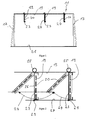
- FIG. 1 shows an embodiment of the solar system according to the invention, which is designated overall by the reference numeral 11. As holding elements in this embodiment, two substantially parallel guided guide ropes or guide rods 13 are provided. The guide cables or rods 13 are stretched or guided between two supports 17.
- a bifacial solar panel 19 On the guide cables or guide rods 13, a plurality of successively arranged bifacial solar panels 19 is held. If under this application is spoken by a bifacial solar panel 19, it is thus preferably a plate with two substantially parallel flat sides disclosed, wherein on the plate photovoltaic cells 20 are arranged, which receive sunlight on both cell surfaces. It is also conceivable that conventional photovoltaic cells 22 are arranged on both flat sides of the plate. Preferably, therefore, both flat sides of a solar panel are used for the photovoltaic conversion of the sunlight. On the one side of the solar panel 19, a glass pane 26 can be arranged to protect the photovoltaic cells 20, 22.
- the bifacial solar panels 19 depend substantially vertically on the guide ropes or rods 13. Although this vertical orientation has the disadvantage that the photovoltaic cells are not optimally adapted to the respective position of the sun. However, the shade of the agricultural area 21 under the solar system 11 is low. Due to the bifacial design of the solar panels 19, the lack of alignment of the solar panels 19 can be compensated. The inventive solar system 11 is therefore suitable to use agricultural land in addition to solar systems.
- the bifacial solar panels 19 are received in frame 23.
- the frame is rotatable in the direction of arrow 24, for example, with a hinge, attached to the guide ropes or rods 13 and serves as a link of the solar panels 19 to the guide cables or rods 13. So that the solar panels 19 is not uncontrollably offset by wind rocking is they are held in a basic position by a damping element 25.
- a damping element 25 Preferably, the basic position of vertical alignment, since the solar panels 19, due to their weight, returns automatically after deflection in the vertical position.
- the damping element may be a spring or an elastomer. If the solar panels 19 deflected from the basic position, the damping element is placed under tensile or compressive stress and rotates the solar panels 19 back to the normal position.
- the solar panels 19 may be held by ropes 27 in the basic position.
- the ropes 27 are guided on the side edge of the frame 23 by eyelets 29. So that the support structure is not overstressed, a small deflection movement of the solar panels 19 is provided. But this is to be damped, so that the deflection movement remains controllable.
- the ropes 27 can also be used be transferred together, the solar panels 19 in a deflected position to adjust the orientation to the position of the sun (dotted solar panels 19 in FIG. 2 ).
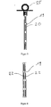
- FIGS. 3 and 4 Solar panels 19 are shown without glass 26. Since the solar panels 19 preferably have a vertical orientation, they are exposed to horizontal rainfall such as hailstorm, heavy rainfall or snowfall only limited. Therefore, the provision of a protective glass is not absolutely necessary. Such solar panels 19 are at least 50% lighter than solar panels with glass panels. This has the advantage that the holder of the solar panels 10 can be dimensioned smaller. Since the solar panels 19 of the solar system 11 are suspended, solar panels without glass panes also from a safety point of view of great advantage, since no overhead glass is present and no appropriate security measures are necessary.
- a glass-free solar panel 19 is shown in which bifacial photovoltaic cells 20 are used.
- FIG. 22 unilaterally usable photovoltaic cells 22 are arranged on both sides of the solar panels 19 in order to be able to use both sides of the solar panel 19 to convert light into electricity.
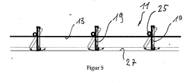
- FIG. 5 is unlike the Figures 1 and 2 the joint or the pivot point of the solar panel 19 is not arranged at its upper side edge, but is offset in a position which is spaced from the upper side edge. This arrangement of the solar panels 19 relative to the guide cable 13 reduces the shadow of the guide cable 13 on the solar panel 19th
Landscapes
- Engineering & Computer Science (AREA)
- Life Sciences & Earth Sciences (AREA)
- Sustainable Development (AREA)
- Physics & Mathematics (AREA)
- Sustainable Energy (AREA)
- Thermal Sciences (AREA)
- Chemical & Material Sciences (AREA)
- Combustion & Propulsion (AREA)
- Mechanical Engineering (AREA)
- General Engineering & Computer Science (AREA)
- Photovoltaic Devices (AREA)
Applications Claiming Priority (1)
| Application Number | Priority Date | Filing Date | Title |
|---|---|---|---|
| CH00752/12A CH706583A1 (de) | 2012-05-31 | 2012-05-31 | Solaranlage. |
Publications (1)
| Publication Number | Publication Date |
|---|---|
| EP2669596A1 true EP2669596A1 (fr) | 2013-12-04 |
Family
ID=48485080
Family Applications (1)
| Application Number | Title | Priority Date | Filing Date |
|---|---|---|---|
| EP13170052.8A Withdrawn EP2669596A1 (fr) | 2012-05-31 | 2013-05-31 | Installation solaire |
Country Status (2)
| Country | Link |
|---|---|
| EP (1) | EP2669596A1 (fr) |
| CH (1) | CH706583A1 (fr) |
Cited By (15)
| Publication number | Priority date | Publication date | Assignee | Title |
|---|---|---|---|---|
| DE202014105516U1 (de) | 2014-11-17 | 2014-12-23 | Solarworld Ag | Photovoltaik-Anlage, Modulhalter-System und Reflektor |
| JPWO2015029728A1 (ja) * | 2013-08-29 | 2017-03-02 | パナソニックIpマネジメント株式会社 | 太陽電池システム |
| CN108279712A (zh) * | 2018-04-17 | 2018-07-13 | 北京理工大学珠海学院 | 电动推杆式双轴太阳跟踪系统 |
| JP2020503828A (ja) * | 2016-12-23 | 2020-01-30 | ネクスト2サン ゲー・エム・ベー・ハーNext2Sun GmbH | 太陽光発電装置および該装置の使用 |
| CN111459193A (zh) * | 2016-01-04 | 2020-07-28 | 耐克斯特拉克尔有限公司 | 具有两个光敏面的太阳能电池组件的方向的控制方法 |
| US11165384B1 (en) | 2018-05-18 | 2021-11-02 | Joseph McCABE | Method for hanging PV modules |
| WO2022029107A1 (fr) * | 2020-08-04 | 2022-02-10 | Johann Czaloun | Installation photovoltaïque dotée d'une structure porteuse à câble |
| FR3139379A1 (fr) * | 2022-09-06 | 2024-03-08 | Engie | Système photovoltaïque vertical et procédé d’installation d’un tel système |
| EP4362323A1 (fr) * | 2022-05-26 | 2024-05-01 | Jose Raul Gonzalez Ruisanchez | Installation solaire photovoltaïque aérienne |
| DE102022004547A1 (de) | 2022-12-05 | 2024-06-06 | Sinn Power Gmbh | Solaranlage zu Land und zu Wasser |
| EP4472065A1 (fr) * | 2023-05-29 | 2024-12-04 | Tecna Energy Srl | Terrain des panneaux solaires photovoltaïques bifaces |
| SE2351170A1 (en) * | 2023-10-11 | 2025-04-12 | Vaja Ab | Solar panel suspension systems, solar cell assembly, and solar cell rod |
| CH721347A1 (de) * | 2023-12-01 | 2025-06-13 | Bkw Energie Ag | Photovoltaikrahmenanordnung |
| DE102024109244A1 (de) * | 2024-04-03 | 2025-10-09 | Vecon Gmbh | Rahmen für ein Fotovoltaikmodul |
| AT528249A1 (de) * | 2024-05-07 | 2025-11-15 | Htb Baugesellschaft M B H | Befestigungsvorrichtung zur Befestigung eines Photovoltaikpaneels |
Citations (6)
| Publication number | Priority date | Publication date | Assignee | Title |
|---|---|---|---|---|
| WO2006130892A1 (fr) | 2005-06-06 | 2006-12-14 | Innova Patent Gmbh | Installation de production d'energie electrique |
| EP2020467A1 (fr) * | 2007-08-02 | 2009-02-04 | Corradi S.r.l. | Store avec des panneaux solaires |
| WO2010006460A2 (fr) | 2008-07-14 | 2010-01-21 | Solar Wings Ag | Installation solaire |
| US20100077592A1 (en) | 2008-10-01 | 2010-04-01 | Peter Casano | System and method for hanging solar panels from a horizontal support |
| US20110005583A1 (en) | 2009-07-07 | 2011-01-13 | Rodney Harold Thomas | Solar Capture Mounting Systems And Methods |
| EP2398064A1 (fr) * | 2010-06-16 | 2011-12-21 | ET Solutions AG | Installation photovoltaïque à surface libre pour l'agriculture |
-
2012
- 2012-05-31 CH CH00752/12A patent/CH706583A1/de not_active Application Discontinuation
-
2013
- 2013-05-31 EP EP13170052.8A patent/EP2669596A1/fr not_active Withdrawn
Patent Citations (6)
| Publication number | Priority date | Publication date | Assignee | Title |
|---|---|---|---|---|
| WO2006130892A1 (fr) | 2005-06-06 | 2006-12-14 | Innova Patent Gmbh | Installation de production d'energie electrique |
| EP2020467A1 (fr) * | 2007-08-02 | 2009-02-04 | Corradi S.r.l. | Store avec des panneaux solaires |
| WO2010006460A2 (fr) | 2008-07-14 | 2010-01-21 | Solar Wings Ag | Installation solaire |
| US20100077592A1 (en) | 2008-10-01 | 2010-04-01 | Peter Casano | System and method for hanging solar panels from a horizontal support |
| US20110005583A1 (en) | 2009-07-07 | 2011-01-13 | Rodney Harold Thomas | Solar Capture Mounting Systems And Methods |
| EP2398064A1 (fr) * | 2010-06-16 | 2011-12-21 | ET Solutions AG | Installation photovoltaïque à surface libre pour l'agriculture |
Cited By (28)
| Publication number | Priority date | Publication date | Assignee | Title |
|---|---|---|---|---|
| JPWO2015029728A1 (ja) * | 2013-08-29 | 2017-03-02 | パナソニックIpマネジメント株式会社 | 太陽電池システム |
| DE102015119849A1 (de) | 2014-11-17 | 2016-05-19 | Solarworld Ag | Photovoltaik-Anlage, Modulhalter-System und Reflektor |
| DE202014105516U1 (de) | 2014-11-17 | 2014-12-23 | Solarworld Ag | Photovoltaik-Anlage, Modulhalter-System und Reflektor |
| CN111459193A (zh) * | 2016-01-04 | 2020-07-28 | 耐克斯特拉克尔有限公司 | 具有两个光敏面的太阳能电池组件的方向的控制方法 |
| CN111459193B (zh) * | 2016-01-04 | 2023-11-17 | 耐克斯特拉克尔有限公司 | 具有两个光敏面的太阳能电池组件的方向的控制方法 |
| JP2020503828A (ja) * | 2016-12-23 | 2020-01-30 | ネクスト2サン ゲー・エム・ベー・ハーNext2Sun GmbH | 太陽光発電装置および該装置の使用 |
| EP3683960A1 (fr) * | 2016-12-23 | 2020-07-22 | Next2Sun GmbH | Installation photovoltaïque |
| EP3687060A3 (fr) * | 2016-12-23 | 2020-10-21 | Next2Sun GmbH | Installation photovoltaïque |
| US11411525B2 (en) | 2016-12-23 | 2022-08-09 | Next2Sun GmbH | Photovoltaic system and associated use |
| JP2022133457A (ja) * | 2016-12-23 | 2022-09-13 | ネクスト2サン ゲー・エム・ベー・ハー | 太陽光発電装置および該装置の使用 |
| JP2024063134A (ja) * | 2016-12-23 | 2024-05-10 | ネクスト2サン ゲー・エム・ベー・ハー | 太陽光発電装置および該装置の使用 |
| JP2024063133A (ja) * | 2016-12-23 | 2024-05-10 | ネクスト2サン ゲー・エム・ベー・ハー | 太陽光発電装置および該装置の使用 |
| CN108279712B (zh) * | 2018-04-17 | 2024-02-27 | 北京理工大学珠海学院 | 电动推杆式双轴太阳跟踪系统 |
| CN108279712A (zh) * | 2018-04-17 | 2018-07-13 | 北京理工大学珠海学院 | 电动推杆式双轴太阳跟踪系统 |
| US11165384B1 (en) | 2018-05-18 | 2021-11-02 | Joseph McCABE | Method for hanging PV modules |
| WO2022029107A1 (fr) * | 2020-08-04 | 2022-02-10 | Johann Czaloun | Installation photovoltaïque dotée d'une structure porteuse à câble |
| EP4362323A1 (fr) * | 2022-05-26 | 2024-05-01 | Jose Raul Gonzalez Ruisanchez | Installation solaire photovoltaïque aérienne |
| FR3139379A1 (fr) * | 2022-09-06 | 2024-03-08 | Engie | Système photovoltaïque vertical et procédé d’installation d’un tel système |
| WO2024052347A1 (fr) | 2022-09-06 | 2024-03-14 | Engie | Système photovoltaïque vertical et procédé d'installation d'un tel système |
| DE102022004547A1 (de) | 2022-12-05 | 2024-06-06 | Sinn Power Gmbh | Solaranlage zu Land und zu Wasser |
| US12603603B2 (en) | 2022-12-05 | 2026-04-14 | Sinn Power Gmbh | Solar energy system on land and water |
| EP4472065A1 (fr) * | 2023-05-29 | 2024-12-04 | Tecna Energy Srl | Terrain des panneaux solaires photovoltaïques bifaces |
| SE2351170A1 (en) * | 2023-10-11 | 2025-04-12 | Vaja Ab | Solar panel suspension systems, solar cell assembly, and solar cell rod |
| WO2025080193A1 (fr) * | 2023-10-11 | 2025-04-17 | Vaja Ab | Systèmes de suspension de panneau solaire et panneaux solaires adaptables au vent |
| SE547659C2 (en) * | 2023-10-11 | 2025-11-04 | Vaja Ab | A solar suspension system for suspending wind-responsive panels above ground |
| CH721347A1 (de) * | 2023-12-01 | 2025-06-13 | Bkw Energie Ag | Photovoltaikrahmenanordnung |
| DE102024109244A1 (de) * | 2024-04-03 | 2025-10-09 | Vecon Gmbh | Rahmen für ein Fotovoltaikmodul |
| AT528249A1 (de) * | 2024-05-07 | 2025-11-15 | Htb Baugesellschaft M B H | Befestigungsvorrichtung zur Befestigung eines Photovoltaikpaneels |
Also Published As
| Publication number | Publication date |
|---|---|
| CH706583A1 (de) | 2013-12-13 |
Similar Documents
| Publication | Publication Date | Title |
|---|---|---|
| EP2669596A1 (fr) | Installation solaire | |
| DE102016015436B4 (de) | Photovoltaik-Anlage mit bifazialen Photovoltaik-Modulen | |
| DE3643487A1 (de) | Anlage zur gewinnung elektrischer energie | |
| DE4142565A1 (de) | Vorrichtung zum beschatten von flaechen mit einer aufgespannten dachhaut und an dieser vorgesehenen photovoltaischen elementen | |
| DE112013003631T5 (de) | Einachsige Sonnenverfolgungsanordnung | |
| EP2313707A2 (fr) | Installation solaire | |
| WO2022029107A1 (fr) | Installation photovoltaïque dotée d'une structure porteuse à câble | |
| CH710397B1 (de) | Solarmodulkonstruktion. | |
| DE102011116926B3 (de) | Bodenstütze | |
| DE102005055258B4 (de) | Verfahren zur Steuerung einer Montierung für eine Gruppe von Solarmodulen | |
| DE69334032T2 (de) | Parabolantennenstruktur | |
| DE10192244B4 (de) | Nachführvorrichtung | |
| EP2398064A1 (fr) | Installation photovoltaïque à surface libre pour l'agriculture | |
| WO2006130892A1 (fr) | Installation de production d'energie electrique | |
| DE202022102108U1 (de) | Trägersystem zur Halterung mehrerer Photovoltaikmodule | |
| DE102004013590B4 (de) | Solarkonzentrator mit mehreren Spiegeln | |
| DE202009011880U1 (de) | Modulanordnung aus Solarmodulen | |
| WO2018185128A1 (fr) | Structure porteuse de câbles pour modules pv | |
| DE202010012272U1 (de) | Modulanordnung aus Solarmodulen | |
| EP1770340A2 (fr) | Dispositif pour la fixature et le pointage de collecteurs solaires | |
| WO2022017656A1 (fr) | Structure de support destinée à supporter des modules solaires et des éléments de plafond | |
| DE4020032C2 (de) | Vorrichtung zur Umwandlung von Sonnenenergie in Strom, insbesondere zum Nachladen der Batterien elektrisch angetriebener Fahrzeuge | |
| DE202023102930U1 (de) | Freiland-Photovoltaikeinrichtung | |
| DE102022113611A1 (de) | System zur Überdachung von Pflanzenkulturen | |
| DE102008013477A1 (de) | Solarmodulträger (Tracker) |
Legal Events
| Date | Code | Title | Description |
|---|---|---|---|
| PUAI | Public reference made under article 153(3) epc to a published international application that has entered the european phase |
Free format text: ORIGINAL CODE: 0009012 |
|
| AK | Designated contracting states |
Kind code of ref document: A1 Designated state(s): AL AT BE BG CH CY CZ DE DK EE ES FI FR GB GR HR HU IE IS IT LI LT LU LV MC MK MT NL NO PL PT RO RS SE SI SK SM TR |
|
| AX | Request for extension of the european patent |
Extension state: BA ME |
|
| 17P | Request for examination filed |
Effective date: 20140604 |
|
| RBV | Designated contracting states (corrected) |
Designated state(s): AL AT BE BG CH CY CZ DE DK EE ES FI FR GB GR HR HU IE IS IT LI LT LU LV MC MK MT NL NO PL PT RO RS SE SI SK SM TR |
|
| 19U | Interruption of proceedings before grant |
Effective date: 20141223 |
|
| 19W | Proceedings resumed before grant after interruption of proceedings |
Effective date: 20211001 |
|
| RAP3 | Party data changed (applicant data changed or rights of an application transferred) |
Owner name: LE - LIGHT ENERGY SYSTEMS AG IN NACHTRAGSLIQUIDATION |
|
| STAA | Information on the status of an ep patent application or granted ep patent |
Free format text: STATUS: REQUEST FOR EXAMINATION WAS MADE |
|
| STAA | Information on the status of an ep patent application or granted ep patent |
Free format text: STATUS: THE APPLICATION IS DEEMED TO BE WITHDRAWN |
|
| 18D | Application deemed to be withdrawn |
Effective date: 20220402 |