EP2669687B1 - Synthetische Abschätzung der Eigengeschwindigkeit eines Drehflüglers - Google Patents
Synthetische Abschätzung der Eigengeschwindigkeit eines Drehflüglers Download PDFInfo
- Publication number
- EP2669687B1 EP2669687B1 EP13160597.4A EP13160597A EP2669687B1 EP 2669687 B1 EP2669687 B1 EP 2669687B1 EP 13160597 A EP13160597 A EP 13160597A EP 2669687 B1 EP2669687 B1 EP 2669687B1
- Authority
- EP
- European Patent Office
- Prior art keywords
- angle
- tpp
- estimated
- axis
- aircraft
- Prior art date
- Legal status (The legal status is an assumption and is not a legal conclusion. Google has not performed a legal analysis and makes no representation as to the accuracy of the status listed.)
- Not-in-force
Links
- 230000001133 acceleration Effects 0.000 claims description 23
- 230000006870 function Effects 0.000 claims description 14
- 238000000034 method Methods 0.000 claims description 14
- 238000006073 displacement reaction Methods 0.000 claims description 7
- 230000005484 gravity Effects 0.000 claims description 5
- RZVHIXYEVGDQDX-UHFFFAOYSA-N 9,10-anthraquinone Chemical compound C1=CC=C2C(=O)C3=CC=CC=C3C(=O)C2=C1 RZVHIXYEVGDQDX-UHFFFAOYSA-N 0.000 description 12
- 230000004044 response Effects 0.000 description 6
- 238000010586 diagram Methods 0.000 description 5
- 230000008859 change Effects 0.000 description 4
- 230000003416 augmentation Effects 0.000 description 3
- 125000004122 cyclic group Chemical group 0.000 description 3
- 230000008901 benefit Effects 0.000 description 2
- 238000004088 simulation Methods 0.000 description 2
- 230000004075 alteration Effects 0.000 description 1
- 150000001875 compounds Chemical class 0.000 description 1
- 230000003750 conditioning effect Effects 0.000 description 1
- 230000007547 defect Effects 0.000 description 1
- 230000009977 dual effect Effects 0.000 description 1
- 230000000694 effects Effects 0.000 description 1
- 230000007613 environmental effect Effects 0.000 description 1
- 238000005259 measurement Methods 0.000 description 1
- 238000012986 modification Methods 0.000 description 1
- 230000004048 modification Effects 0.000 description 1
- 230000003287 optical effect Effects 0.000 description 1
- 238000006467 substitution reaction Methods 0.000 description 1
- 230000000153 supplemental effect Effects 0.000 description 1
- 238000009966 trimming Methods 0.000 description 1
Images

Classifications
-
- B—PERFORMING OPERATIONS; TRANSPORTING
- B64—AIRCRAFT; AVIATION; COSMONAUTICS
- B64C—AEROPLANES; HELICOPTERS
- B64C13/00—Control systems or transmitting systems for actuating flying-control surfaces, lift-increasing flaps, air brakes, or spoilers
- B64C13/24—Transmitting means
- B64C13/38—Transmitting means with power amplification
- B64C13/50—Transmitting means with power amplification using electrical energy
- B64C13/503—Fly-by-Wire
-
- G—PHYSICS
- G01—MEASURING; TESTING
- G01P—MEASURING LINEAR OR ANGULAR SPEED, ACCELERATION, DECELERATION, OR SHOCK; INDICATING PRESENCE, ABSENCE, OR DIRECTION, OF MOVEMENT
- G01P5/00—Measuring speed of fluids, e.g. of air stream; Measuring speed of bodies relative to fluids, e.g. of ship, of aircraft
-
- G—PHYSICS
- G05—CONTROLLING; REGULATING
- G05D—SYSTEMS FOR CONTROLLING OR REGULATING NON-ELECTRIC VARIABLES
- G05D1/00—Control of position, course, altitude or attitude of land, water, air or space vehicles, e.g. using automatic pilots
- G05D1/08—Control of attitude, i.e. control of roll, pitch, or yaw
- G05D1/0808—Control of attitude, i.e. control of roll, pitch, or yaw specially adapted for aircraft
- G05D1/0858—Control of attitude, i.e. control of roll, pitch, or yaw specially adapted for aircraft specially adapted for vertical take-off of aircraft
Definitions
- the subject matter disclosed herein relates generally to the field of measurements in a rotary-wing aircraft and, more particularly, to a method and a system for determining an airspeed of a helicopter by utilizing a fly-by-wire system to estimate a tip path plane angle and resolving the steady state speed of the helicopter as a function of the known helicopter parameters.
- FBW fly-by-wire
- US-A-5 214 596 describes a method for determining the airspeed of helicopters. Cyclic and collective control positions, attitude angles for pitch and roll attitudes, and rotational velocities about x, y and z axes of the helicopter are sensed. Models applying these sensed values are used to estimate longitudinal, lateral and vertical velocities of the helicopter to determine airspeed.
- a method for estimating an airspeed of a rotary wing aircraft includes receiving values indicative of operating conditions of the aircraft along an axis; estimating a tip path plane (TPP) angle along the axis from at least one of the operating conditions to create an estimated TPP angle; and determining an estimated airspeed as a function of the estimated TPP angle, the determining including referencing a look-up table that indexes the estimated TPP angle with the airspeed.
- TPP tip path plane
- Particular embodiments may include any of the following optional features, alone or in combination:
- a system for estimating an airspeed of an aircraft includes a memory that indexes an estimated TPP angle with an estimated airspeed of the aircraft; a processor that receives values indicative of operating conditions of the aircraft along an axis and determines the estimated TPP angle along the axis from at least one of the operating conditions; where the processor determines an estimated airspeed as a function of the estimated TPP angle.
- Particular embodiments may include any of the following optional features, alone or in combination:
- Embodiments of an airspeed estimating algorithm includes estimating a TPP angle as a function of a pitch attitude.
- the algorithm estimates the airspeed by utilizing a lookup table that has stored values of several TPP angles against an estimated aircraft airspeed.
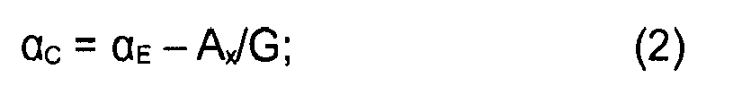
- the estimated airspeed may accommodate acceleration by correcting the estimated TPP angle as a function of the longitudinal acceleration prior to utilizing the lookup table for determining the estimated aircraft speed.
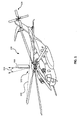
- FIG. 1 illustrates a general perspective view of an exemplary vehicle in the form of a vertical takeoff and landing (VTOL) rotary-wing aircraft 100 for use with estimating the airspeed of the rotary-wing aircraft 100 according to an embodiment of the invention.
- the rotary-wing aircraft 100 includes a main rotor assembly 102 and a tail rotor assembly 104. Also, a tip path plane 106 is shown connecting the rotor blade tips as the rotor blades rotate during flight.
- the TPP 106 is horizontal to the longitudinal axis of the aircraft 100 as it hovers and its thrust vector is oriented along a vertical axis 108.
- the thrust vector When the aircraft 100 travels forward, the thrust vector is rotated slightly in a forward direction, resulting in the TPP angle ( ⁇ ) 110.
- the airspeed of the aircraft 100 may be estimated from the TPP angle 110 as a function of the parameters from a fly-by-wire flight control system 200 utilizing a known relationship between the airspeed of the aircraft and the TPP angle 110.
- a particular helicopter configuration is illustrated and described in disclosed embodiments, other configurations and/or machines, such as high speed compound rotary-wing aircraft with supplemental translational thrust systems, dual contra-rotating coaxial rotor system aircraft, tilt-rotors, tilt-wing aircraft, and unmanned rotary wing aircraft with any of the previous configurations will also benefit from embodiments of the present invention.
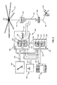
- FIG. 2 illustrates a schematic block diagram of a fly-by-wire flight control system 200 according to an exemplary embodiment.
- the system 200 is stored on a flight control computer system and estimates the TPP angle 110 ( FIG. 1 ) as a function of a displacement of the pilot's controllers 206, 208 in order to provide an estimate of the aircraft 100 airspeed from the TPP angle 110.
- the system 200 includes a Primary Flight Control System (PFCS) 202 and an Automatic Flight Augmentation and Cuing System (FACS) 204.
- PFCS Primary Flight Control System
- FACS Automatic Flight Augmentation and Cuing System
- the PFCS 202 and FACS 204 execute explicit control laws to provide both control and stability augmentation.
- the PFCS 202 is the flight critical portion of the flight control system, while the FACS 204 is the mission critical portion.
- the FACS 204 augments the performance of the PFCS 202.
- pilot commands are shaped directly into desired aircraft responses. These desired commands are then passed through an aircraft model to obtain the control commands required to produce the desired response. The difference between the desired command and the aircraft response is also fed back to drive these errors towards zero, thus improving the model performance.
- the PFCS 202 and FACS 204 each receive the force output command signals of a collective controller 206 on line 212, a cyclic controller 208 on line 214, and the aircraft's sensed parameter signals from sensors 210, on lines 216.
- the collective controller 206 and the cyclic controller 208 may take various forms including sidearm controllers, a yaw pedal system or other such flight controllers.
- the pilot command signals on lines 212, 214 and the sensed parameter signals on lines 216 are shown consolidated within trunk lines 218 and 220 in the PFCS 202 and FACS 204, respectively.
- the PFCS 202 and FACS 204 may each contain separate control channel logic laws for controlling the yaw, pitch, roll and lift axes of the aircraft within the operational flight envelope.
- the logic is included in the PFCS 202 and FACS 204 control modules (schematically represented by blocks 222-228 for the PFCS 202 and blocks 230-236 for the FACS 204).
- the sensed parameter signals from aircraft sensors 210, on lines 216, provide the PFCS 202 and FACS 204 with the aircraft's angular rate and attitude response to the rotor command signals.
- the FACS 204 utilizes an algorithm for estimating the tip path plane angle 110 and uses an airspeed model stored in memory for determining the airspeed of the aircraft based on a known relationship between angle 110 and airspeed, derived through flight test data or simulation.
- the FACS logic utilizes the sideslip envelope to limit the yaw rate available to the pilot for producing a desired response without exceeding the operational flight envelope.
- the PFCS logic provides rotor command signals and the FACS logic provides conditioning and/or trimming of the PFCS four axis logic functions based on the operational flight envelope.
- the PFCS and FACS logic modules interconnect through bus 238 to provide rotor command signals on output lines 240 to a mixing function 242, which communicates commands on lines 252 for the displacement of servos 244 and linkages 246 to control the tip path plane 106 ( FIG. 1 ) of the main rotor 102.
- a mixed command signal is also provided on line 250 to the tail rotor servos 248 which control the thrust of the tail rotor 104 through linkages 250.
- FIG. 3 illustrates a schematic block diagram of an airspeed estimation algorithm 302 implemented by the FACS 204 ( FIG. 2 ) of the fly-by-wire flight control system 200 which communicates with, in an exemplary embodiment, the control law system of the PFCS 202 ( FIG. 2 ) according to an embodiment of the invention.
- the functional block diagram in FIG. 3 illustrates the airspeed estimation algorithm 302 stored in memory 306 on flight control computer system 300 and executed by a microprocessor 304 for implementing the algorithm 302 intended to provide an estimate of the airspeed from the TPP angle 110 ( FIG. 1 ) and as a function of aircraft operational parameters obtained from flight test data or simulated parameters during non-accelerated flight.
- the microprocessor 304 of computer system 302 can be any type of processor (CPU), including a general purpose processor, a digital signal processor, a microcontroller, an application specific integrated circuit, a field programmable gate array, or the like.
- memory 306 may include random access memory (RAM), read only memory (ROM), or other electronic, optical, magnetic, or any other computer readable medium onto which is stored the data and control algorithms described below. It is to be appreciated that the airspeed estimation algorithm 302 described below for estimating the airspeed for travel along the longitudinal axis of aircraft 100 over a reference position but travel along the lateral axis may also be implemented.
- the microprocessor 304 initiates the airspeed estimation algorithm 302 by receiving and storing the aircraft's sensed parameter signals.
- the aircraft's senses parameter signals include several aircraft operating parameters such as, in some non-limiting examples, lateral acceleration, aircraft attitude, aircraft's angular rate in order to estimate the aircrafts sideslip angle.
- the sensed parameter signals are received from appropriate sensors 210 in response to compensation in the flight attitude for, in an example, wind-induced perturbations from a steady-state horizontal flight.
- the flight attitude may be compensated by displacing the controller 206 forward in order to change the longitudinal swash plate position and change the pitch angle ⁇ to move the aircraft 100 forward.
- the pitch angle ⁇ is the angle between the longitudinal axis of the aircraft and a defined reference plane.
- the change in pitch angle ⁇ causes a change in the longitudinal force along the longitudinal axis.
- displacing the controller 206 for moving the aircraft 100 forward causes the rotor to tip backwards in order to compensate for the prevailing wind, resulting in leveling the rotor angle.
- the flight control computer 300 stores one or more lookup tables in memory 306 where operational conditions may be maintained for a particular airframe.
- the one or more tables defines estimates for the airspeed against several TPP angles 110 derived from, in some non-limiting examples, simulated data or flight test data.
- one or more tables that defines estimates for the airspeed against the TPP angle 110 derived from, in some non-limiting examples, simulated data or flight test data may be utilized for estimating the airspeed.
- Embodiments for estimating airspeed described herein may be used in conjunction with a pitot tube system for measuring airspeed.
- the airspeed estimating algorithm may be used to verify proper operation of a pitot tube system. Further, the airspeed estimating algorithm may be used to detect a common mode failure (e.g., icing) across multiple pitot tubes.
- the technical effects and benefits of exemplary embodiments include an airspeed estimating algorithm from a TPP angle.
- the system includes estimating the TPP angle as a function of the pitch attitude and utilizing a lookup table that defines stored values of several TPP angles against estimated aircraft airspeed.
- the algorithm accommodates acceleration of the aircraft by correcting the estimated TPP angle as a function of the longitudinal acceleration.
Landscapes
- Engineering & Computer Science (AREA)
- Aviation & Aerospace Engineering (AREA)
- Physics & Mathematics (AREA)
- General Physics & Mathematics (AREA)
- Automation & Control Theory (AREA)
- Radar, Positioning & Navigation (AREA)
- Remote Sensing (AREA)
- Control Of Position, Course, Altitude, Or Attitude Of Moving Bodies (AREA)
- Traffic Control Systems (AREA)
Claims (15)
- Verfahren zum Schätzen der Fluggeschwindigkeit eines Luftfahrzeugs (100) einschließend:Empfangen von Werten, welche Betriebszustände des Luftfahrzeugs entlang einer Achse (108) beschreiben;Schätzen eines Spitzenpfadebenen(TPP)-Winkels (110) entlang der Achse (108) aus wenigstens einem der Betriebszustände, um einen geschätzten TPP-Winkel (110) zu erzeugen; undBestimmen einer geschätzten Fluggeschwindigkeit als eine Funktion des geschätzten TPP-Winkels (110), wobei das das Bestimmen das Referenzieren einer Nachschlagetabelle einschließt, welche den geschätzten TPP-Winkel (110) mit der Fluggeschwindigkeit verknüpft.
- Verfahren nach Anspruch 1, wobei das Schätzen des TPP-Winkels (110) zusätzlich einschließt, die folgende Formel anzuwenden:

wobei:αE = geschätzter TPP-Winkel (110),K, A, B = Konstanten;θ = Anstellwinkel; undBis = Position der Hauptrotortaumelscheibe. - Verfahren nach Anspruch 2, das zusätzlich einschließt, den geschätzten TPP-Winkel (110) gemäß der folgenden Formel um eine Beschleunigung entlang der Achse (108) zu korrigieren:

wobei:α C = korrigierter TPP-Winkel;Ax = Längsbeschleunigung des Luftfahrzeugs; undG = Beschleunigung aufgrund von Gravitation. - Verfahren nach einem der Ansprüche 1 bis 3, wobei die Achse (108) eine von einer Längsachse oder einer Querachse umfasst.
- Verfahren nach einem der Ansprüche 1 bis 4, wobei die Betriebsbedingungen Querbeschleunigung, Fluglage und Winkelgeschwindigkeit einschließen.
- Verfahren nach einem der Ansprüche 1 bis 5, wobei der TPP-Winkel (110) mit einer Verlagerung eines Steuerelements korrespondiert.
- Verfahren nach einem der Ansprüche 1 bis 6, das zusätzlich einschließt, wenigstens einen Betriebszustand von einem oder mehreren Sensoren (210) zu empfangen.
- Verfahren nach einem der Ansprüche 1 bis 7, wobei die Achse (108) dem Anstellwinkel entspricht.
- System (200) zum Schätzen der Fluggeschwindigkeit eines Luftfahrzeugs, aufweisend:einen Speicher (306), der in einer Nachschlagetabelle einen geschätzten TPP-Winkel (110) mit einer geschätzten Fluggeschwindigkeit des Luftfahrzeugs verknüpft,einen Prozessor (304), der Werte empfängt, die Betriebsbedingungen des Luftfahrzeugs entlang einer Achse (108) beschreiben, und der aus wenigstens einer der Betriebsbedingungen den geschätzten TPP-Winkel (110) entlang der Achse (108) bestimmt;wobei der Prozessor (304) eine geschätzte Fluggeschwindigkeit als Funktion des geschätzten TPP-Winkels (110) bestimmt.
- System (200) nach Anspruch 9, wobei der Prozessor (304) den geschätzten TPP-Winkel (110) gemäß der folgenden Gleichung bestimmt:

wobei:α E = der geschätzte TPP-Winkel (110),K, A, B = Konstanten;θ = Anstellwinkel; undBis = Position der Hauptrotortaumelscheibe. - System (200) nach Anspruch 10, wobei der Prozessor (304) den geschätzten TPP-Winkel (110) gemäß der folgenden Gleichung um eine Beschleunigung entlang der Achse (108) korrigiert:
wobei:α C = der korrigierte TPP-Winkel;Ax = Längsbeschleunigung des Luftfahrzeugs; undG = Beschleunigung aufgrund von Gravitation. - System (200) nach einem der Ansprüche 9 bis 11, wobei die Achse (108) eine von einer Längsachse und einer Querachse umfasst.
- System (200) nach einem der Ansprüche 9 bis 12, wobei die Betriebsbedingungen Längsbeschleunigung, Fluglage und Winkelgeschwindigkeit umfassen.
- System (200) nach einem der Ansprüche 9 bis 13, wobei der geschätzte TPP-Winkel (110) mit einer Verlagerung eines Steuerelements korrespondiert.
- System (200) nach einem der Ansprüche 9 bis 14, wobei die Achse (108) mit dem Anstellwinkel korrespondiert.
Applications Claiming Priority (1)
| Application Number | Priority Date | Filing Date | Title |
|---|---|---|---|
| US13/484,761 US8825233B2 (en) | 2012-05-31 | 2012-05-31 | Synthetic estimation of rotorcraft airspeed |
Publications (2)
| Publication Number | Publication Date |
|---|---|
| EP2669687A1 EP2669687A1 (de) | 2013-12-04 |
| EP2669687B1 true EP2669687B1 (de) | 2015-01-28 |
Family
ID=47997106
Family Applications (1)
| Application Number | Title | Priority Date | Filing Date |
|---|---|---|---|
| EP13160597.4A Not-in-force EP2669687B1 (de) | 2012-05-31 | 2013-03-22 | Synthetische Abschätzung der Eigengeschwindigkeit eines Drehflüglers |
Country Status (2)
| Country | Link |
|---|---|
| US (1) | US8825233B2 (de) |
| EP (1) | EP2669687B1 (de) |
Cited By (1)
| Publication number | Priority date | Publication date | Assignee | Title |
|---|---|---|---|---|
| US12304623B2 (en) | 2022-07-08 | 2025-05-20 | Lockheed Martin Corporation | Blended airspeed technique for helicopter control at low airspeeds |
Families Citing this family (10)
| Publication number | Priority date | Publication date | Assignee | Title |
|---|---|---|---|---|
| US9506945B2 (en) * | 2014-06-10 | 2016-11-29 | Sikorsky Aircraft Corporation | Rotorcraft flight parameter estimation |
| US9428279B2 (en) | 2014-07-23 | 2016-08-30 | Honeywell International Inc. | Systems and methods for airspeed estimation using actuation signals |
| WO2016039834A2 (en) * | 2014-08-29 | 2016-03-17 | Sikorsky Aircraft Corporation | Vector limiting of a rotor control volume |
| EP2998817B1 (de) * | 2014-09-16 | 2017-06-07 | Aviovision | System zur Berechnung der Flugzeugleistung und Verfahren zu deren Durchführung |
| CN105424971B (zh) * | 2015-12-24 | 2019-08-16 | 太原航空仪表有限公司 | 一种用于旋翼飞机小速度测量的静压探头 |
| US10605822B2 (en) * | 2017-06-12 | 2020-03-31 | The Boeing Company | System for estimating airspeed of an aircraft based on a weather buffer model |
| FR3102856B1 (fr) * | 2019-11-05 | 2021-10-01 | Airbus Helicopters | Procédé et dispositif d’estimation d’une vitesse air d’un giravion par analyse de son rotor. |
| US11447244B1 (en) | 2021-06-29 | 2022-09-20 | Beta Air, Llc | System and method for airspeed estimation utilizing propulsor data in electric vertical takeoff and landing aircraft |
| US12234010B2 (en) | 2021-10-05 | 2025-02-25 | Lockheed Martin Corporation | System and method for low speed wind estimation in VTOL aircraft |
| CN115856359B (zh) * | 2023-02-15 | 2023-06-09 | 成都凯天电子股份有限公司 | 一种直升机空速在线修正方法 |
Family Cites Families (14)
| Publication number | Priority date | Publication date | Assignee | Title |
|---|---|---|---|---|
| US2524747A (en) | 1943-08-13 | 1950-10-10 | Sperry Corp | Air speed indicating system |
| US2713156A (en) | 1953-12-23 | 1955-07-12 | Louis S Guarino | Rotor tip path plane indicator for helicopter |
| US4300200A (en) | 1978-12-01 | 1981-11-10 | Westland Aircraft Limited | Helicopter airspeed indicating system |
| US4371937A (en) | 1981-03-30 | 1983-02-01 | United Technologies Corporation | Retaining airspeed hold engagement in low speed maneuver |
| DE3677595D1 (de) | 1986-06-02 | 1991-03-28 | Litef Gmbh | Verfahren zur bestimmung der horizontal-eigengeschwindigkeit von hubschraubern in hoeheren geschwindigkeitsbereichen. |
| US5214596A (en) | 1986-06-14 | 1993-05-25 | Duetsche Forchungs- Und Versuchsanstalt Fur Luft- Und Raumfahrt E.V. | System for determining the airspeed of helicopters |
| FR2610411B1 (fr) | 1987-02-04 | 1989-06-09 | Sfim | Procede et dispositif de mesure de la vitesse par rapport a l'air d'un helicoptere a basse vitesse |
| FR2613078B1 (fr) | 1987-03-26 | 1990-12-28 | Crouzet Sa | Dispositif de mesure de la vitesse air d'un helicoptere |
| US5437419A (en) * | 1992-11-06 | 1995-08-01 | The United States Of America As Represented By The United States National Aeronautics And Space Administration | Rotorcraft blade-vortex interaction controller |
| US5850615A (en) | 1995-12-06 | 1998-12-15 | Mcdonnell Douglas Helicopter Co. | Rotor blade swashplate-axis rotation and gyroscopic moments componsator |
| US5751609A (en) | 1996-10-24 | 1998-05-12 | The United States Of America As Represented By The Secretary Of The Navy | Neural network based method for estimating helicopter low airspeed |
| DE10315590A1 (de) | 2003-04-05 | 2004-10-28 | Stefan Reich | Mess- und Regelungssystem für Hubschrauber |
| US8694182B2 (en) | 2007-04-03 | 2014-04-08 | Sikorsky Aircraft Corporation | Altitude and acceleration command altitude hold algorithm for rotorcraft with large center of gravity range |
| FR2921635B1 (fr) | 2007-09-27 | 2010-06-04 | Eurocopter France | Procede et dispositif de detection et de signalisation de l'approche du domaine de vortex par un giravion |
-
2012
- 2012-05-31 US US13/484,761 patent/US8825233B2/en active Active
-
2013
- 2013-03-22 EP EP13160597.4A patent/EP2669687B1/de not_active Not-in-force
Cited By (1)
| Publication number | Priority date | Publication date | Assignee | Title |
|---|---|---|---|---|
| US12304623B2 (en) | 2022-07-08 | 2025-05-20 | Lockheed Martin Corporation | Blended airspeed technique for helicopter control at low airspeeds |
Also Published As
| Publication number | Publication date |
|---|---|
| EP2669687A1 (de) | 2013-12-04 |
| US20130325218A1 (en) | 2013-12-05 |
| US8825233B2 (en) | 2014-09-02 |
Similar Documents
| Publication | Publication Date | Title |
|---|---|---|
| EP2669687B1 (de) | Synthetische Abschätzung der Eigengeschwindigkeit eines Drehflüglers | |
| US11846953B2 (en) | System and method for controlling differential thrust of a blown lift aircraft | |
| EP2940547B1 (de) | Mischen für koaxialen rotor bei niedriger geschwindigkeit | |
| EP2500792B1 (de) | Verstellbare maximal steuerbare Rollengeschwindigkeit für die Richtungssteuerung eines Flugzeugs während eines Rollmanövers mit Motorpanne | |
| CN108482657B (zh) | 用于验证旋翼飞行器位置坐标的系统和方法 | |
| JP6195237B2 (ja) | Qtw機の飛行制御システム | |
| EP3670335A1 (de) | Verfahren und system zur längssteuerung eines flugzeugs | |
| US10351230B2 (en) | Initial rotor state compensation for a rotorcraft | |
| EP4553601A1 (de) | Kollektive steuerung unter verwendung von vertikaler geschwindigkeit | |
| US8718841B2 (en) | Method and system for providing sideslip envelope protection | |
| JP2022184747A (ja) | 少なくとも2つのエンジンを含む回転翼機の操縦を支援するための方法 | |
| US10710706B2 (en) | Self-adjusting system for aircraft control | |
| KR20260035832A (ko) | Evtol 항공기의 비행 제어에 가동 노치 필터를 적용하기 위한 시스템 및 방법 | |
| EP2955106B1 (de) | Schätzung der flugparameter eines drehflüglers | |
| US20220187849A1 (en) | Method for piloting a hybrid helicopter having an airframe maintained at constant incidence by regulating a position of at least one mobile tail unit surface | |
| EP4163643B1 (de) | System und verfahren zur niedriggeschwindigkeitswindschätzung in einem vtol-flugzeug | |
| Dantsker et al. | Flight testing instrumentation development and integration for a subscale integrated high lift propulsor testbed | |
| Muraoka et al. | Flight Verification of Automatic Flight and Transition System for Lift/Cruise Thrust Type VTOL Aircraft | |
| Gilyard | In-flight transport performance optimization: An experimental flight research program and an operational scenario | |
| Kubo et al. | High angle of attack flight characteristics of a wing-in-propeller-slipstream aircraft | |
| IL278514A (en) | Aircraft based optimization system and method therefor | |
| US20260084830A1 (en) | Angle-of-attack (aoa) integrity monitoring |
Legal Events
| Date | Code | Title | Description |
|---|---|---|---|
| PUAI | Public reference made under article 153(3) epc to a published international application that has entered the european phase |
Free format text: ORIGINAL CODE: 0009012 |
|
| AK | Designated contracting states |
Kind code of ref document: A1 Designated state(s): AL AT BE BG CH CY CZ DE DK EE ES FI FR GB GR HR HU IE IS IT LI LT LU LV MC MK MT NL NO PL PT RO RS SE SI SK SM TR |
|
| AX | Request for extension of the european patent |
Extension state: BA ME |
|
| 17P | Request for examination filed |
Effective date: 20140507 |
|
| RBV | Designated contracting states (corrected) |
Designated state(s): AL AT BE BG CH CY CZ DE DK EE ES FI FR GB GR HR HU IE IS IT LI LT LU LV MC MK MT NL NO PL PT RO RS SE SI SK SM TR |
|
| GRAP | Despatch of communication of intention to grant a patent |
Free format text: ORIGINAL CODE: EPIDOSNIGR1 |
|
| INTG | Intention to grant announced |
Effective date: 20140905 |
|
| GRAS | Grant fee paid |
Free format text: ORIGINAL CODE: EPIDOSNIGR3 |
|
| GRAA | (expected) grant |
Free format text: ORIGINAL CODE: 0009210 |
|
| AK | Designated contracting states |
Kind code of ref document: B1 Designated state(s): AL AT BE BG CH CY CZ DE DK EE ES FI FR GB GR HR HU IE IS IT LI LT LU LV MC MK MT NL NO PL PT RO RS SE SI SK SM TR |
|
| REG | Reference to a national code |
Ref country code: GB Ref legal event code: FG4D |
|
| REG | Reference to a national code |
Ref country code: CH Ref legal event code: EP |
|
| REG | Reference to a national code |
Ref country code: IE Ref legal event code: FG4D |
|
| REG | Reference to a national code |
Ref country code: DE Ref legal event code: R096 Ref document number: 602013000911 Country of ref document: DE Effective date: 20150312 |
|
| REG | Reference to a national code |
Ref country code: AT Ref legal event code: REF Ref document number: 708459 Country of ref document: AT Kind code of ref document: T Effective date: 20150315 |
|
| REG | Reference to a national code |
Ref country code: FR Ref legal event code: PLFP Year of fee payment: 3 |
|
| REG | Reference to a national code |
Ref country code: AT Ref legal event code: MK05 Ref document number: 708459 Country of ref document: AT Kind code of ref document: T Effective date: 20150128 |
|
| REG | Reference to a national code |
Ref country code: NL Ref legal event code: VDEP Effective date: 20150128 |
|
| REG | Reference to a national code |
Ref country code: LT Ref legal event code: MG4D |
|
| PG25 | Lapsed in a contracting state [announced via postgrant information from national office to epo] |
Ref country code: ES Free format text: LAPSE BECAUSE OF FAILURE TO SUBMIT A TRANSLATION OF THE DESCRIPTION OR TO PAY THE FEE WITHIN THE PRESCRIBED TIME-LIMIT Effective date: 20150128 Ref country code: HR Free format text: LAPSE BECAUSE OF FAILURE TO SUBMIT A TRANSLATION OF THE DESCRIPTION OR TO PAY THE FEE WITHIN THE PRESCRIBED TIME-LIMIT Effective date: 20150128 Ref country code: NO Free format text: LAPSE BECAUSE OF FAILURE TO SUBMIT A TRANSLATION OF THE DESCRIPTION OR TO PAY THE FEE WITHIN THE PRESCRIBED TIME-LIMIT Effective date: 20150428 Ref country code: FI Free format text: LAPSE BECAUSE OF FAILURE TO SUBMIT A TRANSLATION OF THE DESCRIPTION OR TO PAY THE FEE WITHIN THE PRESCRIBED TIME-LIMIT Effective date: 20150128 Ref country code: LT Free format text: LAPSE BECAUSE OF FAILURE TO SUBMIT A TRANSLATION OF THE DESCRIPTION OR TO PAY THE FEE WITHIN THE PRESCRIBED TIME-LIMIT Effective date: 20150128 Ref country code: BG Free format text: LAPSE BECAUSE OF FAILURE TO SUBMIT A TRANSLATION OF THE DESCRIPTION OR TO PAY THE FEE WITHIN THE PRESCRIBED TIME-LIMIT Effective date: 20150428 Ref country code: SE Free format text: LAPSE BECAUSE OF FAILURE TO SUBMIT A TRANSLATION OF THE DESCRIPTION OR TO PAY THE FEE WITHIN THE PRESCRIBED TIME-LIMIT Effective date: 20150128 |
|
| PG25 | Lapsed in a contracting state [announced via postgrant information from national office to epo] |
Ref country code: AT Free format text: LAPSE BECAUSE OF FAILURE TO SUBMIT A TRANSLATION OF THE DESCRIPTION OR TO PAY THE FEE WITHIN THE PRESCRIBED TIME-LIMIT Effective date: 20150128 Ref country code: GR Free format text: LAPSE BECAUSE OF FAILURE TO SUBMIT A TRANSLATION OF THE DESCRIPTION OR TO PAY THE FEE WITHIN THE PRESCRIBED TIME-LIMIT Effective date: 20150429 Ref country code: PL Free format text: LAPSE BECAUSE OF FAILURE TO SUBMIT A TRANSLATION OF THE DESCRIPTION OR TO PAY THE FEE WITHIN THE PRESCRIBED TIME-LIMIT Effective date: 20150128 Ref country code: LV Free format text: LAPSE BECAUSE OF FAILURE TO SUBMIT A TRANSLATION OF THE DESCRIPTION OR TO PAY THE FEE WITHIN THE PRESCRIBED TIME-LIMIT Effective date: 20150128 Ref country code: NL Free format text: LAPSE BECAUSE OF FAILURE TO SUBMIT A TRANSLATION OF THE DESCRIPTION OR TO PAY THE FEE WITHIN THE PRESCRIBED TIME-LIMIT Effective date: 20150128 Ref country code: IS Free format text: LAPSE BECAUSE OF FAILURE TO SUBMIT A TRANSLATION OF THE DESCRIPTION OR TO PAY THE FEE WITHIN THE PRESCRIBED TIME-LIMIT Effective date: 20150528 Ref country code: RS Free format text: LAPSE BECAUSE OF FAILURE TO SUBMIT A TRANSLATION OF THE DESCRIPTION OR TO PAY THE FEE WITHIN THE PRESCRIBED TIME-LIMIT Effective date: 20150128 |
|
| REG | Reference to a national code |
Ref country code: DE Ref legal event code: R097 Ref document number: 602013000911 Country of ref document: DE |
|
| PG25 | Lapsed in a contracting state [announced via postgrant information from national office to epo] |
Ref country code: SK Free format text: LAPSE BECAUSE OF FAILURE TO SUBMIT A TRANSLATION OF THE DESCRIPTION OR TO PAY THE FEE WITHIN THE PRESCRIBED TIME-LIMIT Effective date: 20150128 Ref country code: MC Free format text: LAPSE BECAUSE OF FAILURE TO SUBMIT A TRANSLATION OF THE DESCRIPTION OR TO PAY THE FEE WITHIN THE PRESCRIBED TIME-LIMIT Effective date: 20150128 Ref country code: RO Free format text: LAPSE BECAUSE OF FAILURE TO SUBMIT A TRANSLATION OF THE DESCRIPTION OR TO PAY THE FEE WITHIN THE PRESCRIBED TIME-LIMIT Effective date: 20150128 Ref country code: DK Free format text: LAPSE BECAUSE OF FAILURE TO SUBMIT A TRANSLATION OF THE DESCRIPTION OR TO PAY THE FEE WITHIN THE PRESCRIBED TIME-LIMIT Effective date: 20150128 Ref country code: EE Free format text: LAPSE BECAUSE OF FAILURE TO SUBMIT A TRANSLATION OF THE DESCRIPTION OR TO PAY THE FEE WITHIN THE PRESCRIBED TIME-LIMIT Effective date: 20150128 Ref country code: LU Free format text: LAPSE BECAUSE OF FAILURE TO SUBMIT A TRANSLATION OF THE DESCRIPTION OR TO PAY THE FEE WITHIN THE PRESCRIBED TIME-LIMIT Effective date: 20150322 Ref country code: CZ Free format text: LAPSE BECAUSE OF FAILURE TO SUBMIT A TRANSLATION OF THE DESCRIPTION OR TO PAY THE FEE WITHIN THE PRESCRIBED TIME-LIMIT Effective date: 20150128 |
|
| PLBE | No opposition filed within time limit |
Free format text: ORIGINAL CODE: 0009261 |
|
| STAA | Information on the status of an ep patent application or granted ep patent |
Free format text: STATUS: NO OPPOSITION FILED WITHIN TIME LIMIT |
|
| PG25 | Lapsed in a contracting state [announced via postgrant information from national office to epo] |
Ref country code: IT Free format text: LAPSE BECAUSE OF FAILURE TO SUBMIT A TRANSLATION OF THE DESCRIPTION OR TO PAY THE FEE WITHIN THE PRESCRIBED TIME-LIMIT Effective date: 20150128 |
|
| 26N | No opposition filed |
Effective date: 20151029 |
|
| REG | Reference to a national code |
Ref country code: IE Ref legal event code: MM4A |
|
| PG25 | Lapsed in a contracting state [announced via postgrant information from national office to epo] |
Ref country code: IE Free format text: LAPSE BECAUSE OF NON-PAYMENT OF DUE FEES Effective date: 20150322 |
|
| REG | Reference to a national code |
Ref country code: FR Ref legal event code: PLFP Year of fee payment: 4 |
|
| PG25 | Lapsed in a contracting state [announced via postgrant information from national office to epo] |
Ref country code: SI Free format text: LAPSE BECAUSE OF FAILURE TO SUBMIT A TRANSLATION OF THE DESCRIPTION OR TO PAY THE FEE WITHIN THE PRESCRIBED TIME-LIMIT Effective date: 20150128 |
|
| PG25 | Lapsed in a contracting state [announced via postgrant information from national office to epo] |
Ref country code: BE Free format text: LAPSE BECAUSE OF FAILURE TO SUBMIT A TRANSLATION OF THE DESCRIPTION OR TO PAY THE FEE WITHIN THE PRESCRIBED TIME-LIMIT Effective date: 20150128 |
|
| REG | Reference to a national code |
Ref country code: CH Ref legal event code: PL |
|
| PG25 | Lapsed in a contracting state [announced via postgrant information from national office to epo] |
Ref country code: MT Free format text: LAPSE BECAUSE OF FAILURE TO SUBMIT A TRANSLATION OF THE DESCRIPTION OR TO PAY THE FEE WITHIN THE PRESCRIBED TIME-LIMIT Effective date: 20150128 |
|
| PG25 | Lapsed in a contracting state [announced via postgrant information from national office to epo] |
Ref country code: LI Free format text: LAPSE BECAUSE OF NON-PAYMENT OF DUE FEES Effective date: 20160331 Ref country code: CH Free format text: LAPSE BECAUSE OF NON-PAYMENT OF DUE FEES Effective date: 20160331 |
|
| REG | Reference to a national code |
Ref country code: FR Ref legal event code: PLFP Year of fee payment: 5 |
|
| PG25 | Lapsed in a contracting state [announced via postgrant information from national office to epo] |
Ref country code: HU Free format text: LAPSE BECAUSE OF FAILURE TO SUBMIT A TRANSLATION OF THE DESCRIPTION OR TO PAY THE FEE WITHIN THE PRESCRIBED TIME-LIMIT; INVALID AB INITIO Effective date: 20130322 |
|
| PG25 | Lapsed in a contracting state [announced via postgrant information from national office to epo] |
Ref country code: CY Free format text: LAPSE BECAUSE OF FAILURE TO SUBMIT A TRANSLATION OF THE DESCRIPTION OR TO PAY THE FEE WITHIN THE PRESCRIBED TIME-LIMIT Effective date: 20150128 |
|
| REG | Reference to a national code |
Ref country code: DE Ref legal event code: R082 Ref document number: 602013000911 Country of ref document: DE Representative=s name: SCHMITT-NILSON SCHRAUD WAIBEL WOHLFROM PATENTA, DE |
|
| PG25 | Lapsed in a contracting state [announced via postgrant information from national office to epo] |
Ref country code: TR Free format text: LAPSE BECAUSE OF FAILURE TO SUBMIT A TRANSLATION OF THE DESCRIPTION OR TO PAY THE FEE WITHIN THE PRESCRIBED TIME-LIMIT Effective date: 20150128 |
|
| REG | Reference to a national code |
Ref country code: FR Ref legal event code: PLFP Year of fee payment: 6 |
|
| PG25 | Lapsed in a contracting state [announced via postgrant information from national office to epo] |
Ref country code: SM Free format text: LAPSE BECAUSE OF FAILURE TO SUBMIT A TRANSLATION OF THE DESCRIPTION OR TO PAY THE FEE WITHIN THE PRESCRIBED TIME-LIMIT Effective date: 20150128 |
|
| PG25 | Lapsed in a contracting state [announced via postgrant information from national office to epo] |
Ref country code: PT Free format text: LAPSE BECAUSE OF FAILURE TO SUBMIT A TRANSLATION OF THE DESCRIPTION OR TO PAY THE FEE WITHIN THE PRESCRIBED TIME-LIMIT Effective date: 20150128 Ref country code: MK Free format text: LAPSE BECAUSE OF FAILURE TO SUBMIT A TRANSLATION OF THE DESCRIPTION OR TO PAY THE FEE WITHIN THE PRESCRIBED TIME-LIMIT Effective date: 20150128 |
|
| PG25 | Lapsed in a contracting state [announced via postgrant information from national office to epo] |
Ref country code: AL Free format text: LAPSE BECAUSE OF FAILURE TO SUBMIT A TRANSLATION OF THE DESCRIPTION OR TO PAY THE FEE WITHIN THE PRESCRIBED TIME-LIMIT Effective date: 20150128 |
|
| PGFP | Annual fee paid to national office [announced via postgrant information from national office to epo] |
Ref country code: GB Payment date: 20200327 Year of fee payment: 8 Ref country code: DE Payment date: 20200327 Year of fee payment: 8 |
|
| PGFP | Annual fee paid to national office [announced via postgrant information from national office to epo] |
Ref country code: FR Payment date: 20200325 Year of fee payment: 8 |
|
| REG | Reference to a national code |
Ref country code: DE Ref legal event code: R119 Ref document number: 602013000911 Country of ref document: DE |
|
| GBPC | Gb: european patent ceased through non-payment of renewal fee |
Effective date: 20210322 |
|
| PG25 | Lapsed in a contracting state [announced via postgrant information from national office to epo] |
Ref country code: FR Free format text: LAPSE BECAUSE OF NON-PAYMENT OF DUE FEES Effective date: 20210331 Ref country code: GB Free format text: LAPSE BECAUSE OF NON-PAYMENT OF DUE FEES Effective date: 20210322 Ref country code: DE Free format text: LAPSE BECAUSE OF NON-PAYMENT OF DUE FEES Effective date: 20211001 |