EP2669730A2 - Dispositif d'affichage d'image stéréoscopique - Google Patents
Dispositif d'affichage d'image stéréoscopique Download PDFInfo
- Publication number
- EP2669730A2 EP2669730A2 EP12739523.4A EP12739523A EP2669730A2 EP 2669730 A2 EP2669730 A2 EP 2669730A2 EP 12739523 A EP12739523 A EP 12739523A EP 2669730 A2 EP2669730 A2 EP 2669730A2
- Authority
- EP
- European Patent Office
- Prior art keywords
- region
- signal
- retardation layer
- right eye
- state
- Prior art date
- Legal status (The legal status is an assumption and is not a legal conclusion. Google has not performed a legal analysis and makes no representation as to the accuracy of the status listed.)
- Withdrawn
Links
- 239000011521 glass Substances 0.000 claims abstract description 69
- 230000003287 optical effect Effects 0.000 claims abstract description 62
- 238000010521 absorption reaction Methods 0.000 claims description 70
- 230000000694 effects Effects 0.000 abstract description 7
- 230000002411 adverse Effects 0.000 abstract description 3
- 239000010410 layer Substances 0.000 description 138
- 239000004973 liquid crystal related substance Substances 0.000 description 16
- 238000000034 method Methods 0.000 description 15
- CNQCVBJFEGMYDW-UHFFFAOYSA-N lawrencium atom Chemical compound [Lr] CNQCVBJFEGMYDW-UHFFFAOYSA-N 0.000 description 11
- -1 poly(methyl methacrylate) Polymers 0.000 description 9
- 230000005540 biological transmission Effects 0.000 description 8
- 239000004642 Polyimide Substances 0.000 description 4
- 239000010408 film Substances 0.000 description 4
- 238000004519 manufacturing process Methods 0.000 description 4
- 229920001721 polyimide Polymers 0.000 description 4
- 239000000758 substrate Substances 0.000 description 4
- 229920002284 Cellulose triacetate Polymers 0.000 description 3
- NNLVGZFZQQXQNW-ADJNRHBOSA-N [(2r,3r,4s,5r,6s)-4,5-diacetyloxy-3-[(2s,3r,4s,5r,6r)-3,4,5-triacetyloxy-6-(acetyloxymethyl)oxan-2-yl]oxy-6-[(2r,3r,4s,5r,6s)-4,5,6-triacetyloxy-2-(acetyloxymethyl)oxan-3-yl]oxyoxan-2-yl]methyl acetate Chemical compound O([C@@H]1O[C@@H]([C@H]([C@H](OC(C)=O)[C@H]1OC(C)=O)O[C@H]1[C@@H]([C@@H](OC(C)=O)[C@H](OC(C)=O)[C@@H](COC(C)=O)O1)OC(C)=O)COC(=O)C)[C@@H]1[C@@H](COC(C)=O)O[C@@H](OC(C)=O)[C@H](OC(C)=O)[C@H]1OC(C)=O NNLVGZFZQQXQNW-ADJNRHBOSA-N 0.000 description 3
- 150000001875 compounds Chemical class 0.000 description 3
- 239000004698 Polyethylene Substances 0.000 description 2
- 239000004743 Polypropylene Substances 0.000 description 2
- 229920002678 cellulose Polymers 0.000 description 2
- 239000001913 cellulose Substances 0.000 description 2
- 239000003795 chemical substances by application Substances 0.000 description 2
- 229920005994 diacetyl cellulose Polymers 0.000 description 2
- 229920002313 fluoropolymer Polymers 0.000 description 2
- 239000004811 fluoropolymer Substances 0.000 description 2
- 229920003023 plastic Polymers 0.000 description 2
- 239000004033 plastic Substances 0.000 description 2
- 229920003229 poly(methyl methacrylate) Polymers 0.000 description 2
- 229920002492 poly(sulfone) Polymers 0.000 description 2
- 229920000058 polyacrylate Polymers 0.000 description 2
- 229920002530 polyetherether ketone Polymers 0.000 description 2
- 229920001601 polyetherimide Polymers 0.000 description 2
- 229920000573 polyethylene Polymers 0.000 description 2
- 229920000139 polyethylene terephthalate Polymers 0.000 description 2
- 239000005020 polyethylene terephthalate Substances 0.000 description 2
- 239000004926 polymethyl methacrylate Substances 0.000 description 2
- 229920001155 polypropylene Polymers 0.000 description 2
- 229920002451 polyvinyl alcohol Polymers 0.000 description 2
- 230000001105 regulatory effect Effects 0.000 description 2
- 239000002356 single layer Substances 0.000 description 2
- 229920000089 Cyclic olefin copolymer Polymers 0.000 description 1
- 238000005618 Fries rearrangement reaction Methods 0.000 description 1
- 229920012266 Poly(ether sulfone) PES Polymers 0.000 description 1
- NIXOWILDQLNWCW-UHFFFAOYSA-N acrylic acid group Chemical group C(C=C)(=O)O NIXOWILDQLNWCW-UHFFFAOYSA-N 0.000 description 1
- 238000006243 chemical reaction Methods 0.000 description 1
- 238000007697 cis-trans-isomerization reaction Methods 0.000 description 1
- 230000000052 comparative effect Effects 0.000 description 1
- 238000006471 dimerization reaction Methods 0.000 description 1
- 238000011156 evaluation Methods 0.000 description 1
- 230000005484 gravity Effects 0.000 description 1
- AMGQUBHHOARCQH-UHFFFAOYSA-N indium;oxotin Chemical compound [In].[Sn]=O AMGQUBHHOARCQH-UHFFFAOYSA-N 0.000 description 1
- 239000000463 material Substances 0.000 description 1
- 238000005259 measurement Methods 0.000 description 1
- 150000002848 norbornenes Chemical class 0.000 description 1
- 230000000704 physical effect Effects 0.000 description 1
- 230000010287 polarization Effects 0.000 description 1
- 239000004417 polycarbonate Substances 0.000 description 1
- 229920000515 polycarbonate Polymers 0.000 description 1
- 229920000728 polyester Polymers 0.000 description 1
- 229920000642 polymer Polymers 0.000 description 1
- 229920000098 polyolefin Polymers 0.000 description 1
- 239000010409 thin film Substances 0.000 description 1
Images



Classifications
-
- G—PHYSICS
- G02—OPTICS
- G02B—OPTICAL ELEMENTS, SYSTEMS OR APPARATUS
- G02B30/00—Optical systems or apparatus for producing three-dimensional [3D] effects, e.g. stereoscopic images
- G02B30/20—Optical systems or apparatus for producing three-dimensional [3D] effects, e.g. stereoscopic images by providing first and second parallax images to an observer's left and right eyes
- G02B30/22—Optical systems or apparatus for producing three-dimensional [3D] effects, e.g. stereoscopic images by providing first and second parallax images to an observer's left and right eyes of the stereoscopic type
- G02B30/25—Optical systems or apparatus for producing three-dimensional [3D] effects, e.g. stereoscopic images by providing first and second parallax images to an observer's left and right eyes of the stereoscopic type using polarisation techniques
-
- H—ELECTRICITY
- H04—ELECTRIC COMMUNICATION TECHNIQUE
- H04N—PICTORIAL COMMUNICATION, e.g. TELEVISION
- H04N13/00—Stereoscopic video systems; Multi-view video systems; Details thereof
- H04N13/30—Image reproducers
- H04N13/332—Displays for viewing with the aid of special glasses or head-mounted displays [HMD]
- H04N13/337—Displays for viewing with the aid of special glasses or head-mounted displays [HMD] using polarisation multiplexing
Definitions
- the present invention relates to a stereoscopic image display device and glasses for observing a stereoscopic image.
- a stereoscopic image display device is a display device that can deliver three-dimensional (3D) information to an observer.
- Methods of displaying a stereoscopic image may be largely classified into a method using glasses and a method that doesn't use glasses. Also, the method using glasses may be classified again into a method using polarizing glasses and a method using LC shutter glasses, and the method that doesn't use glasses may be classified again into binocular disparity/multi-view autostereoscopic display methods, volumetric display methods and holographic display methods.
- the present invention provides a stereoscopic image display device and glasses for observing a stereoscopic image.
- One illustrative stereoscopic image display device may be a device, a stereoscopic image emitted from which may be observed after wearing glasses for observing the stereoscopic image.
- the stereoscopic image display device may include a display element, a first polarizing plate and a filter.
- the display element, the first polarizing plate and the filter may be sequentially arranged so that a signal generated at the display element may be incident on the filter after passing through the first polarizing plate and then be transmitted through the filter to an observer wearing the glasses.
- each of the terms may refer to substantial numerical values or mean substantially vertical, horizontal, perpendicular or parallel without causing damage to desired effects.
- each of the terms is used in consideration of manufacturing errors or variations. Therefore, each of the terms may, for example, include an error of not more than approximately ⁇ 15 degrees, an error of not more than approximately ⁇ 10 degrees, or an error of not more than approximately ⁇ 5 degrees.
- the term “same” used for defining length, width, thickness and pitch or description of the relationships of the length, the width, the thickness or the pitch may also mean substantially the same without causing damage to desired effects.
- the term is used in consideration of manufacturing errors or variations. Therefore, the term “same” may, for example, include an error of not more than approximately ⁇ 60 ⁇ m, an error of not more than approximately ⁇ 40 ⁇ m, or an error of not more than approximately ⁇ 20 ⁇ m.
- observation's direction or “direction along which a signal is transmitted” as used herein may refer to a direction along which a signal generated at the display element travels to the observer in a driving state.
- the direction may refer to a direction indicated by the arrow in Fig. 1 .
- driving state or "displaying state of the stereoscopic image” as used herein may refer to a state in which the stereoscopic image display device is in a driving state, i.e., the stereoscopic image is displayed to the observer.
- Fig. 1 shows a schematic of one illustrative embodiment of the display device.
- the arrow in Fig. 1 represents a direction along which a signal is transmitted from the display device, and the observer 106 may wear the glasses and observe the stereoscopic image.
- the display device 10 of Fig. 1 includes a display element 103 and a first polarizing plate 104. Also, the display device 10 includes a filter 105 on which a signal transmitted from the display element 103 and passing through the first polarizing plate 104 is incident.
- the display device 10 may further include a second polarizing plate 102 and a light source 101, which are sequentially arranged on the display element 103 and disposed on the opposite side of the first polarizing plate 104.
- the first and second polarizing plates 102 and 104 in the display device 10 may be optical devices in which a transmission axis and an absorption axis perpendicular to the transmission axis are formed. Thus, if light is incident on the first and second polarizing plates 102 and 104, only a signal having a polarization axis parallel to the transmission axis may be transmitted through the first and second polarizing plates 102 and 104.
- the first and second polarizing plates 102 and 104 included in the display device 10 may be optical devices, each of which includes an absorption axis and a transmission axis.
- the first polarizing plate 104 and the second polarizing plate 102 in the display device may be arranged so that the absorption axis of the first polarizing plate 104 may be positioned to be perpendicular to the absorption axis of the second polarizing plate 102.
- the transmission axes of the first and second polarizing plates 102 and 104 may also be perpendicular to each other.
- a direct-type or edge-type backlight unit (BLU) generally used in liquid crystal displays (LCDs) may be, for example, used as the light source 101.
- Other various kinds of light sources may also be used as the light source 101 without limitation.
- the display element may include a region (hereinafter, referred to as "LS region”) configured to generate a signal (hereinafter, referred to as "L signal”) for a left eye in the driving state, and a region (hereinafter, referred to as "RS region”) configured to generate a signal (hereinafter, referred to as "R signal”) in the driving state.
- LS region region
- RS region region
- R signal signal
- a transmissive liquid crystal display panel having a liquid crystal layer formed between two substrates may be used as such a display element.
- This type of the display panel may, for example, include a first substrate, a pixel electrode, a first alignment film, a liquid crystal layer, a second alignment film, a common electrode and a second substrate, which are sequentially arranged from one side of the light source 101.
- an active-type drive circuit including a thin film transistor (TFT) and wires may be formed on the substrate disposed at a side of the light source 101.
- the pixel electrode may include indium tin oxide (ITO) and function as an electrode in each pixel.
- the first or second alignment film may include, for example, a material such as a polyimide.
- the liquid crystal layer may include, for example, a liquid crystal in a vertical alignment (VA), twisted nematic (TN), super-twisted nematic (STN) or in-plane switching (IPS) mode. According to a voltage applied from the drive circuit, the liquid crystal layer may transmit lights from the light source 11 through each pixel or intercept the lights by each pixel.
- the common electrode may include ITO, and function as a common counter electrode.
- LS and RS regions including at least one pixel may be formed.
- one unit pixel including liquid crystals sealed between respective alignment films, or at least two unit pixels may form the LS and RS regions.
- the LS and RS regions may be arranged in row and/or column directions.
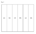
- Fig. 2 shows a schematic of one illustrative embodiment of the arrangement of the RS and LS regions.
- the RS and LS regions may have stripe shapes extending in the same direction, and may be alternately arranged adjacent to each other.
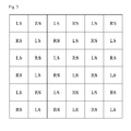
- Fig. 3 shows a schematic of other illustrative embodiment of the arrangement of the RS and LS regions.
- the RS and LS regions may be alternately arranged adjacent to each other in a lattice pattern.
- the arrangement of RS and LS regions is not limited to the arrangements as shown in Figs. 2 and 3 , and a variety of designs known in the art are applicable.
- the display panel may generate signals including the R and L signal by driving the pixel in each region according to signals in the driving state and then transmit the generated signals toward the observer.
- the signals including the R and L signals are incident on the first polarizing plate 104, only the lights polarized parallel to the transmission axis of the polarizing plate 104 may be transmitted through the first polarizing plate 104.
- the filter 105 may be arranged on one side of the first polarizing plate 104, opposite side to the display element 103, as shown in Fig. 1 . As described above, the signal which is generated at the display element 103 may pass through the filter 105 after passing through the first polarizing plate 104 and then be transmitted to the observer 106.
- the filter 105 may include a polarization-state-control region (hereinafter, referred to as "RC region”) for the R signal arranged so that the R signal among the signals transferred from the display element 103 can be incident on, and a polarization-state-control region (hereinafter referred to as "LC region”) for the L signal arranged so that the L signal among the signals transferred from the display element 103 can be incident on.
- RC region polarization-state-control region
- LC region polarization-state-control region
- Each of the LC and RC regions may include a retardation layer.
- the LC region may include a retardation layer of which an optical axis is formed in a first direction
- the RC region may include a retardation layer of which an optical axis is formed in a second direction different from the first direction.
- optical axis as used herein may refer to a fast axis or a slow axis when lights penetrate a corresponding region. Unless particularly defined otherwise, the optical axis may refer to the slow axis.
- the RC region of the filter 105 may have a size corresponding to that of the RS region and be positioned in a position corresponding to that of the RS region so that the R signal generated and transmitted from the RS region in the driving state may be incident on
- the LS region may have a size corresponding to that of the LS region and be position in a position corresponding to that of the LS region so that the L signal generated and transmitted from the LS region in the driving state may be incident on.
- the size or the position of the RC or LC region, corresponding to that of the RS or LS region may mean a size or a position, determined in order for the R signal generated from the RS region to be incident on the RC region and for the L signal generated from the LS region to be incident on the LC region, but doesn't mean that the size or the position of the RC or LC region should be identical to that of the RS or LS region.
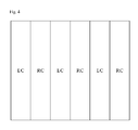
- the RC and LC regions may be formed in stripe shapes extending in the same direction, and be alternately arranged adjacent to each other; or may be alternately arranged adjacent to each other in a lattice pattern, according to the arrangement of RS and LS regions of the display element.
- the RC and LC regions may be arranged in a shape as shown in Fig. 4 .
- the RC and LC regions may be arranged in a shape as shown in Fig. 5 .
- the signals after passing through the RC region and the signals after passing through the LC region in the driving state may have different polarized states from each other.
- one signal of the signals after passing through the RC region and after passing through the LC region may be a left-circularly polarized signal
- the other signal may be a right-circularly polarized signal.
- the R signal generated at the display element may be incident on the RC region after passing through the first polarizing plate, and then be emitted as the left-circularly polarized light or the right-circularly polarized light.
- the L signal may be incident on the LC region after passing through the first polarizing plate, and then be emitted as the right-circularly polarized light or the left-circularly polarized light, of which a rotating direction is opposite to that of the R signal.
- a filter in which the retardation layer included in the RC and LC regions is a ⁇ /4 wavelength layer may be used as the filter capable of outputting the left-circularly signal and the right-circularly polarized signal.
- the ⁇ /4 wavelength layer on the RC region and the ⁇ /4 wavelength layer on the LC region may be formed so that the optical axis of the ⁇ /4 wavelength layer in the RC region may be different from the optical axis of the ⁇ /4 wavelength layer in the LC region.
- the RC region may include a ⁇ /4 wavelength layer having the optical axis in a first direction as the retardation layer
- the LC region may include a ⁇ /4 wavelength layer having the optical axis in a second direction different from the first direction as the retardation layer.
- ⁇ /4 wavelength layer as used herein may refer to a phase retardation device configured to phase-retard incident light by 1/4 times of a wavelength of the incident light.
- the filter including a 3 ⁇ /4 wavelength layer in one region of the RC and LC regions and a ⁇ /4 wavelength layer in the other region of the RC and LC region may generate the left-circularly polarized light and the right-circularly polarized light.
- the term "3 ⁇ /4 wavelength layer" as used herein may refer to a phase retardation device configured to phase-retard incident light by 3/4 times of a wavelength of the incident light. Such a device may be manufactured, for example, by stacking a ⁇ /2 wavelength layer and the ⁇ /4 wavelength layer.
- the ⁇ /2 wavelength layer may phase-retard incident light by 1/2 times of a wavelength of the incident light.
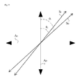
- Fig. 6 shows a schematic of one illustrative embodiment that can be used for explaining the directions of the optical axes of the RC and LC regions as shown in Fig. 4 or 5 .
- the optical axis formed in the first direction is indicated by "A1" in the LC region
- the optical axis formed in the second direction is indicated by "A2" in the RC region.
- the optical axes A1 and A2 of the RC and LC regions may be formed so that a line bisecting an angle formed by the optical axes A1 and A2 may be parallel or perpendicular to the absorption axis of the first polarizing plate. Due to the arrangement of the optical axes, the signal generated at the display element and having passed through the polarizing plate may be precisely converted into the left-circularly polarized light and the right-circularly polarized light. Thus, excellent stereoscopic image qualities may be realized, and side effects such as a so-called crosstalk may be prevented. Referring to Fig.
- the term "line bisecting an angle formed by the optical axes” may refer to a line bisecting an angle of " ⁇ 1+ ⁇ 2" or "360-( ⁇ 1+ ⁇ 2)." For example, if ⁇ 1 and ⁇ 2 are the same angle, the line bisecting the angle may be formed to be horizontal with respect to the boundary line "L" between the RC and LC regions.
- the optical axes A1 and A2 of the RC and LC regions may be formed in vertical directions with respect to each other.
- this state may refer to a state in which the angle of " ⁇ 1+ ⁇ 2" or "360-( ⁇ 1+ ⁇ 2)" is substantially 90 degrees as shown in Fig. 6 . Due to the arrangement of the optical axes, excellent stereoscopic image qualities such as viewing angle and contrast ratio may be realized, and the crosstalk may also be prevented.
- the filter according to one embodiment may further include a base layer.
- the retardation layer such as the ⁇ /4 wavelength layer may be formed on the base layer.
- the ⁇ /4 wavelength layer may be arranged so as to face the display element, and the base layer may be arranged so as to face the observer.
- conventional glass base layers or plastic base layers known in the art may be used as the base layer.
- the plastic base layer may include a cellulose base layer such as a triacetyl cellulose (TAC) layer or a diacetyl cellulose (DAC) layer ; a base layer formed from cycloolefin polymer such as a norbornene derivative; an acrylic base layer formed from acrylic polymer such as poly(methyl methacrylate) (PMMA); a polycarbonate (PC) base layer; a polyolefin base layer such as a polyethylene (PE) layer or a polypropylene (PP) layer ; a poly(vinyl alcohol) (PVA) base layer; a poly(ether sulfone) (PES) base layer; a poly(etheretherketone) (PEEK) base layer; a poly(etherimide) (PEI) base layer; a poly(ethylene naphthalate) (PEN) base layer; a polyester base layer such as a poly(ethylene terephthalate) (PET) layer; a polyimi
- the base layer may have a single-layer structure or a multilayer structure, but the base layer having a single-layer structure is preferred in an aspect of providing an element having a smaller thickness.
- a thickness of the base is not particularly limited, but may be properly regulated according to a desired purpose of use.
- the retardation layer such as the ⁇ /4 wavelength layer, which may be formed on the base layer, may include an alignment layer formed on the base layer and a liquid crystal layer formed on the alignment layer.
- the liquid crystal layer may be a ⁇ /4 wavelength layer having an optical axis formed in different directions according to regions, and the alignment layer formed under the liquid crystal layer may be a layer functioning to control the optical axis of the wavelength layer.
- a conventional alignment layer known in the art may be used as the alignment layer.
- the alignment layer usable herein may include a photo-alignment layer whose alignment may be determined by a reaction such as cistrans isomerization, fries rearrangement or dimerization reaction induced by an irradiation with linearly polarized lights and which may induce alignments of the adjacent liquid crystal layer by the determined alignment; a polymer layer such as a rubbed polyimide layer; or a curable acrylic polymer layer formed in which a plurality of grooves are formed in a certain pattern.
- the liquid crystal layer is widely known in the art, and may be a photocrosslinked layer or photo-polymerized layer of photo-crosslinkable or photopolymerizable liquid crystal compounds.
- a variety of liquid crystal compounds showing the above-described characteristics are known in the art.
- Examples of the liquid crystal compound may include reactive mesogen (RM, commercially available from Merck) or LC242 (commercially available from BASF).
- Methods of manufacturing the filter is not particularly limited, but a variety of methods of manufacturing a filter are widely known in the art. Here, all the methods are applicable in consideration of the relationship between the absorption axis of the polarizing plate and the optical axis of the filter.
- the observer wears the glasses and then observes the R and L signals which have different polarized states from each other and which are emitted from the filter, it is possible to observe the stereoscopic image.
- the glasses may include a region (hereinafter referred to as "GL region”) for the left eye and a region (hereinafter referred to as "GR region”) for the right eye.
- GL region region
- GR region region
- each of the GL and GR regions may include a retardation layer and a polarizer.
- Fig. 7 shows a schematic of one illustrative embodiment of the glasses 70.
- the glasses 70 in Fig. 7 may include the GL region including the retardation layer 701L and the polarizer 702L and also the GR region including the retardation layer 701R and the polarizer 702R.
- An arrow in Fig. 7 may indicate a traveling direction of the R or L signal emitted from the stereoscopic image display device.
- the polarizer included in the glasses may be an optical device having an absorption axis formed in a certain direction, and a transmission axis formed in a direction perpendicular to the absorption axis, as the polarizing plate included in the stereoscopic image display device.
- the polarizers may be arranged in the GR and GL regions, respectively, so that the absorption axis of the polarizer in the GR region may be formed to be parallel to the absorption axis of the polarizer in the GL region.
- the absorption axes of the polarizers which are formed in the parallel directions to each other, may be arranged so that the absorption axes of the polarizers may be formed to be vertical to the absorption axis of the first polarizing plate under the state where the glasses are disposed so that an imaginary line connecting the center of the GL region and the center of the GR region may be formed to be vertical or horizontal with respect to a boundary line between the RC region and the LC region of the stereoscopic image display device. In this state, it is possible to observe a high-quality stereoscopic image.
- imaging line connecting the centers of the GL and GR regions of the glasses may refer to an imaginary line “CL” connecting the centers “C” of the GR and GL regions “GR” and “GL,” as shown in Fig. 8 .
- the center of the each of the regions may refer to the center of gravity.
- the stereoscopic image display device the stereoscopic image emitted from which can be observed after wearing the glasses may satisfy the requirement of the following Formula 1 or 2.
- D L represents a degree by which an optical axis of a retardation layer of the LC region is deviated from an optical axis of a retardation layer of the GL region
- ⁇ 2 represents an angle formed by an optical axis of the retardation layer of the LC region and an absorption axis of a first polarizing plate
- ⁇ L represents an angle formed by the optical axis of the retardation layer of the GL region and the absorption axis of the first polarizing plate under a state where the polarizer of the GL region of the glasses is positioned so as for the absorption axis of the polarizer to be formed to be vertical to the absorption axis of the first polarizing plate
- D R represents a degree by which an optical axis of a retardation layer of the RC region is deviated from an optical axis of a retardation layer of the GR region
- ⁇ 1 represents an angle formed by the optical axis of the retardation layer of the RC region and the ab
- each of the angles of “ ⁇ 1 ,” “ ⁇ 2 ,” “ ⁇ 1 “ and “ ⁇ R” may be an angle measured from the absorption axis of the first polarizing plate in a clockwise or anticlockwise direction.
- each angle applied to the same Formula may be an angle measured in the same direction.
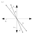
- Fig. 9 shows a schematic of one illustrative embodiment of the relationship of the angles defining the "D L " in Formula 1.
- the angle of the optical axis "S F " of the retardation layer of the LC region measured from the absorption axis "A D " of the first polarizing plate in a clockwise direction under the state where the absorption axis "A D " of the first polarizing plate and the absorption axis "A G “ of the polarizer of the GL region are arranged so as to be vertical to each other is indicated as “ ⁇ 2 .”
- the angle of the optical axis "S G “ of the retardation layer of the GL region measured from the absorption axis "A D " in the clockwise direction is indicated as “ ⁇ L .”
- Fig. 9 shows a schematic of one illustrative embodiment of the relationship of the angles defining the "D L " in Formula 1.
- FIG. 10 shows a schematic of one illustrative embodiment of the relationship of the angles defining the "D R " in Formula 2.
- the angle of the optical axis "S F " of the retardation layer of the RC region measured from the absorption axis "A D " of the first polarizing plate in an anticlockwise direction under the state where the absorption axis "A D " of the first polarizing plate and the absorption axis "A G “ of the polarizer of the GR region are arranged so as to be vertical to each other is indicated as “ ⁇ 1 .”
- the angle of the optical axis "S G” of the retardation layer of the GR region measured from the absorption axis "A D " in the anticlockwise direction is indicated as “ ⁇ R .”
- the "D L " may be, for example, 14 or less, 13 or less, 12 or less, 11 or less, 10 or less, 9 or less, 8 or less, 7 or less, 6 or less or 5 or less. In one embodiment, the "D L " may not be zero. Also, in Formula 2, the “D R " may be, for example, 14 or less, 13 or less, 12 or less, 11 or less, 10 or less, 9 or less, 8 or less, 7 or less, 6 or less or 5 or less. In one embodiment, the "D R " may not be zero.
- the stereoscopic image display device or the glasses may satisfy the Formula 1 or 2, or in another embodiment, the stereoscopic image display device or the glasses may satisfy both of the Formulas 1 and 2.
- the stereoscopic image display device or the glasses may satisfy the requirements of the following Formula 3 or 4.
- D L and D R are the same as defined in the Formulas 1 and 2
- x represents a phase difference value of the retardation layer of the LC or GL region
- y represents a phase difference value of the retardation layer of the RC or GR region.
- the stereoscopic image display device or glasses satisfying the Formulas 3 and 4 may be obtained, for example, by configuring a display device or glasses so as to have the above described deviated angle and the phase difference value described below.
- the phase difference value may be, for example, an in plane phase retardation value of the retardation layer calculated using the following Equation 3, or an in thickness phase retardation value of the retardation layer calculated using the following Equation 4.
- the phase difference value may be the in plane phase retardation value calculated using the following Equation 1.
- R in represents the in plane phase retardation value of the retardation layer
- R th represents the in thickness phase retardation value of the retardation layer
- X represents a refractive index of the retardation layer in an in plane slow axis direction
- Y represents a refractive index of the retardation layer in an in plane fast axis direction
- Z represents a refractive index of the retardation layer in a thickness direction
- D represents a thickness of the retardation layer.
- each refractive index may be, for example, a refractive index measured with respect to light having a wavelength of approximately 550 nm or approximately 589 nm.
- x represents a phase difference value of the retardation layer of the LC or GL region, for example, a phase difference value of the retardation layer of the LC region.
- y represents a phase difference value of the retardation layer of the RC region or GR region, for example, a phase difference value of the retardation layer of the RC region.
- a lower limit of the expression "-0.0199x 2 +4.9777x-306.56” may be, for example, D L -9, D L -8, D L -7, D L -6, D L -5, D L -4, D L -3, D L -2 or D L -1.
- an upper limit of the expression "-0.0199x 2 +4.9777x-306.56” may be, for example, D L +9, D L +8, D L +7, D L +6, D L +5, D L +4, D L +3, D L +2 or D L +1.
- a lower limit of the expression "-0.0199y 2 +4.9777y-306.56” may be, for example, D R -9, D R -8, D R -7, D R -6, D R -5, D R -4, D R -3, D R -2 or D R -1.
- an upper limit of the expression "-0.0199y2 + 4.9777y-306.56” may be, for example, D R +9, D R +8, D R +7, D R +6, D R +5, D R +4, D R +3, D R +2 or D R +1.
- the "D L " in Formula 3 may not be zero, and the “D R “ in Formula 4 may not be zero.
- the stereoscopic image display device or the glasses may satisfy the Formula 3 or 4. In another embodiment, the stereoscopic image display device or the glasses may satisfy both of the Formulas 3 and 4.
- the retardation layers in the RC and LC regions may, for example, have a phase difference value of 100 nm to 200 nm.
- the phase difference value may be the in plane phase retardation value measured using the Equation 3 or the in thickness phase retardation value calculated using the Equation 4.
- the phase difference value may be the plane phase retardation value.
- a variation between the phase difference value of the retardation layer in the GL region and the phase difference value of the retardation layer in the LC region may also be not more than ⁇ 15 nm, not more than ⁇ 12 nm, not more than ⁇ 9 nm, not more than ⁇ 7 nm, not more than ⁇ 6 nm, not more than ⁇ 5 nm, not more than ⁇ 4 nm, or not more than ⁇ 3 nm.
- a variation between the phase difference value of the retardation layer in the GR region and the phase difference value of the retardation layer of the RC region may be not more than ⁇ 15 nm, not more than ⁇ 12 nm, not more than ⁇ 9 nm, not more than ⁇ 7 nm, not more than ⁇ 6 nm, not more than ⁇ 5 nm, not more than ⁇ 4 nm, or not more than ⁇ 3 nm.
- the characteristics of the retardation layer included in the glasses and the filter may be regulated so that the difference in optical properties between the R signal and the L signal can be minimized and a high-quality stereoscopic image can be observed without causing adverse effects such as crosstalk when the stereoscopic image is observed on the display device.
- the present invention relate to glasses, for example, glasses for observing a stereoscopic image.
- the glasses may be used to observe the stereoscopic image output from the stereoscopic image display device.
- the stereoscopic image display may include a display element including LS and RS regions, which are configured to generate the L and R signals, respectively, in the driving state; a first polarizing plate arranged so that the L and R signals generated at the display element may be incident on; and a filter including LC and RC regions which are arranged so that the L and R signals generated at the LS and RS regions may be incident on after passing through the first polarizing plate, respectively, and each of which includes a retardation layer.
- the glasses may have GL and GR regions, and each of the GL and GR regions may include a retardation layer and a polarizer.
- the GL region may be a region on which the L signal output from the stereoscopic image display device is incident
- the GR region may be a region on which the R signal output from the stereoscopic image display device is incident.
- the glasses may satisfy the Formula 1 and/or the Formula 2, and/or satisfy the Formula 3 and/or the Formula 4, as described above.
- the details of the glasses and the details of the stereoscopic image display device outputting the stereoscopic image may be applicable in the same manner as in the details of the above-described stereoscopic image display device.
- the stereoscopic image display device or glasses may be useful in minimizing the difference in optical properties between the R signal and the L signal and observing a high-quality stereoscopic image without causing adverse effects such as so-called crosstalk when the stereoscopic image is observed on the display device.
- Fig. 1 shows a schematic of one illustrative embodiment of a stereoscopic image display device.
- Figs. 2 and 3 show schematics of illustrative embodiments of the arrangement of LS regions and RS regions.
- Figs. 4 and 5 show schematics of illustrative embodiments of the arrangement of LC regions and RC regions.
- Fig. 6 shows a schematic of one illustrative embodiment used for explaining the relationship between the optical axes of retardation layers in the LC and RC regions.
- Figs. 7 and 8 show schematics of illustrative embodiments of glasses for observing a stereoscopic image.
- Figs. 9 and 10 show schematics of illustrative embodiments used for explaining D R and D L .
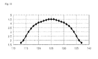
- Fig. 11 shows the relationship between the deviated angle from the optical axis and the phase difference value so as to secure characteristics such as a crosstalk ratio of 1% or less when a stereoscopic image determined in Examples is observed.
- the stereoscopic image display device and the glasses will be described in further detail with reference to Examples and Comparative Examples. However, the following Examples are not intended to limit the scope of the stereoscopic image display device.
- a phase difference value of a retardation layer may be measured using light having a wavelength of 550 nm or 589 nm.
- Sixteen Muller matrixes of the retardation layer may be measured according to the manufacturer's manual using equipment (Axoscan, commercially available from Axomatrics) capable of measuring the sixteen Muller matrixes, and the phase difference may be calculated from these measured values.
- a crosstalk ratio of a stereoscopic image display device may be defined as a ratio of brightness in a dark state and a bright state.
- Crosstalk ratios of the stereoscopic image display devices used in Examples may be, for example, measured using the following method.
- First, glasses for observing the stereoscopic image are positioned at a conventional observation point of the stereoscopic image display device.
- the conventional observation point is a point spaced apart from the center of the stereoscopic image display device by a distance corresponding to 3/2 times a length of the stereoscopic image display device in a horizontal direction.
- the glasses are positioned at such an observation point on the assumption that an observer observes the center of the display device.
- the length in the horizontal direction of the stereoscopic image display device may be a length in a horizontal direction based on of the observer, for example, a horizontal length of the stereoscopic image display device.
- illuminance meters equipment name: SR-UL2 Spectrometer
- the brightness measured in the rear surface of the GL region is brightness in a bright state
- the brightness measured at the rear surface of the GR region is brightness in a dark state.
- a ratio of the brightness in the dark state to the brightness in the bright state ([brightness in the dark state]/[brightness in the bright state]) may be calculated, and the percentage of the ratio may be defined as the crosstalk ratio.
- the crosstalk ratio may also be measured in the same manner as described above, except that the brightness in the bright state and the dark state is measured under a state where the display device outputs the R signal. In this case, the brightness measured at the rear surface of the GL region is brightness in the dark state, and the brightness measured at the rear surface of the GR region is brightness in the bright state.
- a ratio of the brightness in the dark state to the brightness in the bright state ([brightness in the dark state]/[brightness in the bright state]) may be calculated, and the percentage of the ratio may be defined as the crosstalk ratio.
- a display device 10 which had the structure as shown in Fig. 1 , and in which the RS and LS regions of the display element 103 were positioned as shown in Fig. 2 , and the RC and LC regions of the filter 105 were positioned as shown in Fig. 4 was configured.
- a retardation layer having a slow axis forming an angle of 45 degrees with the absorption axis of the first polarizing plate 104 in an anticlockwise direction was positioned in the RC region of the filter, and a retardation layer having a slow axis forming an angle of 45 degrees with the absorption axis of the first polarizing plate 104 in a clockwise direction was positioned in the LC region of the filter.
- the absorption axis of the first polarizing plate 104 was horizontal with respect to the vertical direction of the display device 10
- the absorption axis of the second polarizing plate 102 was vertical with respect to the absorption axis of the first polarizing plate 104.
- a crosstalk ratio in case where an image emitted from the display device 10 was observed using glasses which included the GL and GR regions as shown in Fig. 7 was measured.
- retardation layers 701L and 701R retardation layers, each of which had the in plane phase retardation value (R in ) of 125 nm, were included in the GL and GR regions.
- the absorption axes of the polarizers 702L and 702R were formed in the same direction in the glasses 70. If the imaginary line "CL" as shown in Fig. 8 was positioned to be vertical to the boundary between the LC and RC regions of the display device 10, the absorption axes of the polarizers 702L and 702R were vertical to the absorption axis of the first polarizing plate 104. In such a state, the optical axes of the retardation layers 701L and 701R of the GR or GL region of the glasses or the phase difference value R in of the RC or LC region were variously changed, and the crosstalk ratios were evaluated.
- the "x" axis represents the phase difference value (unit: nm) and the "y” axis represents the relative deviated degree (unit: degrees) of the optical axis.
- the device 10 and glasses 70 were configured in the same manner as in Example 1, except that the absorption axis of the first polarizing plate 104 was formed to be horizontal with respect to the horizontal direction of the display device 10, a retardation layer having a slow axis forming an angle of 45 degrees with the absorption axis of the first polarizing plate in a clockwise direction was positioned in the RC region, and a retardation layer having a slow axis forming an angle of 45 degrees with the absorption axis of the first polarizing plate in an anticlockwise direction was positioned in the LC region. Then, by using the device 10, the crosstalk ratio was measured in the same manner as described above. As a result, if the D L or D R was below approximately 5 degrees or less, the crosstalk ratio was measured to be 1% or less, similar to Example 1.
- the device 10 and glasses 70 were configured in the same manner as in Example 1, except that the absorption axis of the first polarizing plate 104 was formed to form an angle of 45 degrees with a vertical direction of the device 10 in an anticlockwise direction, a retardation layer having a slow axis forming an angle of 45 degrees with the absorption axis of the first polarizing plate 104 in an anticlockwise direction was positioned in the RC region, and a retardation layer having a slow axis forming an angle of 45 degrees with the absorption axis of the first polarizing plate 104 in a clockwise direction was positioned in the LC region. Then, by using the device 10, the crosstalk ratio was measured in the same manner as described above. As a result, if the D L or D R was below approximately 5 degrees or less, the crosstalk ratio was measured to be 1% or less, similar to Example 1.
- the device 10 and glasses 70 were configured in the same manner as in Example 1, except that the absorption axis of the first polarizing plate 104 was formed to form an angle of 45 degrees with a vertical direction of the device 10 in a clockwise direction, a retardation layer having a slow axis forming an angle of 45 degrees with the absorption axis of the first polarizing plate 104 in an anticlockwise direction was positioned in the RC region, and a retardation layer having a slow axis forming an angle of 45 degrees with the absorption axis of the first polarizing plate 104 in a clockwise direction was positioned in the LC region. Then, by using the device 10, the crosstalk ratio was measured in the same manner as described above. As a result, if the D L or D R was below approximately 5 degrees or less, the crosstalk ratio was measured to be 1% or less, similar to Example 1.
Landscapes
- Physics & Mathematics (AREA)
- General Physics & Mathematics (AREA)
- Optics & Photonics (AREA)
- Engineering & Computer Science (AREA)
- Multimedia (AREA)
- Signal Processing (AREA)
- Testing, Inspecting, Measuring Of Stereoscopic Televisions And Televisions (AREA)
- Stereoscopic And Panoramic Photography (AREA)
- Liquid Crystal (AREA)
Applications Claiming Priority (3)
| Application Number | Priority Date | Filing Date | Title |
|---|---|---|---|
| KR20110007440 | 2011-01-25 | ||
| PCT/KR2012/000605 WO2012102550A2 (fr) | 2011-01-25 | 2012-01-25 | Dispositif d'affichage d'image stéréoscopique |
| KR1020120007310A KR101233895B1 (ko) | 2011-01-25 | 2012-01-25 | 입체 영상 표시 장치 |
Publications (2)
| Publication Number | Publication Date |
|---|---|
| EP2669730A2 true EP2669730A2 (fr) | 2013-12-04 |
| EP2669730A4 EP2669730A4 (fr) | 2017-10-18 |
Family
ID=46872179
Family Applications (1)
| Application Number | Title | Priority Date | Filing Date |
|---|---|---|---|
| EP12739523.4A Withdrawn EP2669730A4 (fr) | 2011-01-25 | 2012-01-25 | Dispositif d'affichage d'image stéréoscopique |
Country Status (7)
| Country | Link |
|---|---|
| US (1) | US20120218634A1 (fr) |
| EP (1) | EP2669730A4 (fr) |
| JP (1) | JP2014509402A (fr) |
| KR (1) | KR101233895B1 (fr) |
| CN (1) | CN103348280B (fr) |
| TW (1) | TWI524094B (fr) |
| WO (1) | WO2012102550A2 (fr) |
Families Citing this family (8)
| Publication number | Priority date | Publication date | Assignee | Title |
|---|---|---|---|---|
| TWI417584B (zh) * | 2011-03-03 | 2013-12-01 | Futis Internat Ltd | 微相位差膜之製造方法 |
| KR101556817B1 (ko) * | 2011-03-23 | 2015-10-01 | 주식회사 엘지화학 | 입체 영상 표시 장치 |
| JP6161174B2 (ja) * | 2012-11-29 | 2017-07-12 | エルジー・ケム・リミテッド | 表示装置 |
| TWI490552B (zh) * | 2013-08-20 | 2015-07-01 | Sumika Technology Co Ltd | 立體顯示裝置 |
| CN104297933A (zh) * | 2014-10-14 | 2015-01-21 | 联想(北京)有限公司 | 一种电子设备及眼镜 |
| US10151932B1 (en) * | 2017-09-01 | 2018-12-11 | Volfoni R&D | Stereoscopic three dimensional projection system using elliptical polarization |
| US10520772B1 (en) * | 2017-12-15 | 2019-12-31 | Facebook Technologies, Llc | Self-compensated liquid crystal polymer coatings on curved optical surface |
| CN110927855A (zh) * | 2019-11-15 | 2020-03-27 | 浙江怡诚光电科技有限公司 | 3d显示装置、图样化圆偏光板及制备方法 |
Family Cites Families (12)
| Publication number | Priority date | Publication date | Assignee | Title |
|---|---|---|---|---|
| JP3767962B2 (ja) * | 1997-02-19 | 2006-04-19 | シャープ株式会社 | 映像表示システム |
| JPH11234704A (ja) * | 1998-02-10 | 1999-08-27 | Idemitsu Kosan Co Ltd | 立体表示装置 |
| GB2331883A (en) * | 1997-11-26 | 1999-06-02 | Sharp Kk | Dual image viewing system |
| KR100449879B1 (ko) | 2003-08-18 | 2004-09-22 | 주식회사 참비전 | 입체 영상 표시 장치 |
| TW201005311A (en) * | 2008-07-23 | 2010-02-01 | Ind Tech Res Inst | Test device and method for an SoC test architecture |
| TWI425257B (zh) * | 2008-12-15 | 2014-02-01 | Sony Corp | Phase difference element and display device |
| KR101324440B1 (ko) * | 2009-02-11 | 2013-10-31 | 엘지디스플레이 주식회사 | 입체 영상의 뷰 제어방법과 이를 이용한 입체 영상표시장치 |
| KR101293552B1 (ko) * | 2009-03-20 | 2013-08-06 | 엘지디스플레이 주식회사 | 액정표시장치를 포함하는 다중 전면 화상 구현 시스템 |
| KR101279120B1 (ko) * | 2009-05-15 | 2013-06-26 | 엘지디스플레이 주식회사 | 영상표시장치 |
| KR101318443B1 (ko) * | 2009-05-29 | 2013-10-16 | 엘지디스플레이 주식회사 | 입체영상 표시장치 |
| JP2011039532A (ja) | 2010-09-13 | 2011-02-24 | Sony Corp | 画像分離装置 |
| US8687050B2 (en) * | 2010-12-02 | 2014-04-01 | Tektronix, Inc. | Stereoscopic extinction ratio test pattern |
-
2012
- 2012-01-20 TW TW101102856A patent/TWI524094B/zh active
- 2012-01-25 CN CN201280006505.8A patent/CN103348280B/zh active Active
- 2012-01-25 US US13/358,321 patent/US20120218634A1/en not_active Abandoned
- 2012-01-25 JP JP2013550415A patent/JP2014509402A/ja active Pending
- 2012-01-25 WO PCT/KR2012/000605 patent/WO2012102550A2/fr not_active Ceased
- 2012-01-25 EP EP12739523.4A patent/EP2669730A4/fr not_active Withdrawn
- 2012-01-25 KR KR1020120007310A patent/KR101233895B1/ko active Active
Non-Patent Citations (1)
| Title |
|---|
| See references of WO2012102550A2 * |
Also Published As
| Publication number | Publication date |
|---|---|
| TWI524094B (zh) | 2016-03-01 |
| EP2669730A4 (fr) | 2017-10-18 |
| TW201245769A (en) | 2012-11-16 |
| KR101233895B1 (ko) | 2013-02-15 |
| WO2012102550A3 (fr) | 2012-11-22 |
| WO2012102550A2 (fr) | 2012-08-02 |
| CN103348280B (zh) | 2016-06-29 |
| KR20120086274A (ko) | 2012-08-02 |
| US20120218634A1 (en) | 2012-08-30 |
| JP2014509402A (ja) | 2014-04-17 |
| CN103348280A (zh) | 2013-10-09 |
Similar Documents
| Publication | Publication Date | Title |
|---|---|---|
| EP2669730A2 (fr) | Dispositif d'affichage d'image stéréoscopique | |
| KR20150068033A (ko) | 스위처블 렌즈 장치와 그를 이용한 2d/3d 영상 표시장치 | |
| US9279994B2 (en) | Stereoscopic image display device | |
| KR101314402B1 (ko) | 표시 장치 | |
| CN102419494B (zh) | 显示面板及其应用的显示装置 | |
| KR20130091282A (ko) | 디스플레이 장치 | |
| EP2927732B1 (fr) | Dispositif d'affichage | |
| CN103874954B (zh) | 滤光片 | |
| US20130120675A1 (en) | Polarization assembly and three-dimensional image display apparatus having the same | |
| KR101082056B1 (ko) | 입체 영상 표시 장치 | |
| TWI490551B (zh) | 顯示裝置 | |
| US20120212815A1 (en) | Stereoscopic image display device |
Legal Events
| Date | Code | Title | Description |
|---|---|---|---|
| PUAI | Public reference made under article 153(3) epc to a published international application that has entered the european phase |
Free format text: ORIGINAL CODE: 0009012 |
|
| 17P | Request for examination filed |
Effective date: 20130722 |
|
| AK | Designated contracting states |
Kind code of ref document: A2 Designated state(s): AL AT BE BG CH CY CZ DE DK EE ES FI FR GB GR HR HU IE IS IT LI LT LU LV MC MK MT NL NO PL PT RO RS SE SI SK SM TR |
|
| DAX | Request for extension of the european patent (deleted) | ||
| A4 | Supplementary search report drawn up and despatched |
Effective date: 20170918 |
|
| RIC1 | Information provided on ipc code assigned before grant |
Ipc: G02B 27/26 20060101AFI20170912BHEP Ipc: H04N 13/04 20060101ALI20170912BHEP |
|
| STAA | Information on the status of an ep patent application or granted ep patent |
Free format text: STATUS: THE APPLICATION IS DEEMED TO BE WITHDRAWN |
|
| RAP1 | Party data changed (applicant data changed or rights of an application transferred) |
Owner name: LG CHEM, LTD. |
|
| 18D | Application deemed to be withdrawn |
Effective date: 20180417 |