EP2669735A1 - Dispositif d'affichage transparent - Google Patents
Dispositif d'affichage transparent Download PDFInfo
- Publication number
- EP2669735A1 EP2669735A1 EP13168573.7A EP13168573A EP2669735A1 EP 2669735 A1 EP2669735 A1 EP 2669735A1 EP 13168573 A EP13168573 A EP 13168573A EP 2669735 A1 EP2669735 A1 EP 2669735A1
- Authority
- EP
- European Patent Office
- Prior art keywords
- transparent
- transparent display
- display device
- display panel
- recited
- Prior art date
- Legal status (The legal status is an assumption and is not a legal conclusion. Google has not performed a legal analysis and makes no representation as to the accuracy of the status listed.)
- Withdrawn
Links
- 239000002245 particle Substances 0.000 claims description 9
- 238000000034 method Methods 0.000 claims description 3
- 238000010586 diagram Methods 0.000 description 10
- 239000004973 liquid crystal related substance Substances 0.000 description 5
- 241000282414 Homo sapiens Species 0.000 description 2
- 239000003086 colorant Substances 0.000 description 2
- -1 e.g. Substances 0.000 description 2
- 239000000126 substance Substances 0.000 description 2
- 238000002834 transmittance Methods 0.000 description 2
- 239000000853 adhesive Substances 0.000 description 1
- 230000001070 adhesive effect Effects 0.000 description 1
- 230000001668 ameliorated effect Effects 0.000 description 1
- 210000004556 brain Anatomy 0.000 description 1
- 239000002131 composite material Substances 0.000 description 1
- 230000003287 optical effect Effects 0.000 description 1
- 230000002688 persistence Effects 0.000 description 1
Images


Classifications
-
- G—PHYSICS
- G09—EDUCATION; CRYPTOGRAPHY; DISPLAY; ADVERTISING; SEALS
- G09G—ARRANGEMENTS OR CIRCUITS FOR CONTROL OF INDICATING DEVICES USING STATIC MEANS TO PRESENT VARIABLE INFORMATION
- G09G3/00—Control arrangements or circuits, of interest only in connection with visual indicators other than cathode-ray tubes
- G09G3/20—Control arrangements or circuits, of interest only in connection with visual indicators other than cathode-ray tubes for presentation of an assembly of a number of characters, e.g. a page, by composing the assembly by combination of individual elements arranged in a matrix no fixed position being assigned to or needed to be assigned to the individual characters or partial characters
- G09G3/34—Control arrangements or circuits, of interest only in connection with visual indicators other than cathode-ray tubes for presentation of an assembly of a number of characters, e.g. a page, by composing the assembly by combination of individual elements arranged in a matrix no fixed position being assigned to or needed to be assigned to the individual characters or partial characters by control of light from an independent source
- G09G3/36—Control arrangements or circuits, of interest only in connection with visual indicators other than cathode-ray tubes for presentation of an assembly of a number of characters, e.g. a page, by composing the assembly by combination of individual elements arranged in a matrix no fixed position being assigned to or needed to be assigned to the individual characters or partial characters by control of light from an independent source using liquid crystals
-
- G—PHYSICS
- G02—OPTICS
- G02F—OPTICAL DEVICES OR ARRANGEMENTS FOR THE CONTROL OF LIGHT BY MODIFICATION OF THE OPTICAL PROPERTIES OF THE MEDIA OF THE ELEMENTS INVOLVED THEREIN; NON-LINEAR OPTICS; FREQUENCY-CHANGING OF LIGHT; OPTICAL LOGIC ELEMENTS; OPTICAL ANALOGUE/DIGITAL CONVERTERS
- G02F1/00—Devices or arrangements for the control of the intensity, colour, phase, polarisation or direction of light arriving from an independent light source, e.g. switching, gating or modulating; Non-linear optics
- G02F1/01—Devices or arrangements for the control of the intensity, colour, phase, polarisation or direction of light arriving from an independent light source, e.g. switching, gating or modulating; Non-linear optics for the control of the intensity, phase, polarisation or colour
- G02F1/13—Devices or arrangements for the control of the intensity, colour, phase, polarisation or direction of light arriving from an independent light source, e.g. switching, gating or modulating; Non-linear optics for the control of the intensity, phase, polarisation or colour based on liquid crystals, e.g. single liquid crystal display cells
- G02F1/133—Constructional arrangements; Operation of liquid crystal cells; Circuit arrangements
- G02F1/1333—Constructional arrangements; Manufacturing methods
- G02F1/1343—Electrodes
- G02F1/134309—Electrodes characterised by their geometrical arrangement
- G02F1/134336—Matrix
-
- G—PHYSICS
- G02—OPTICS
- G02F—OPTICAL DEVICES OR ARRANGEMENTS FOR THE CONTROL OF LIGHT BY MODIFICATION OF THE OPTICAL PROPERTIES OF THE MEDIA OF THE ELEMENTS INVOLVED THEREIN; NON-LINEAR OPTICS; FREQUENCY-CHANGING OF LIGHT; OPTICAL LOGIC ELEMENTS; OPTICAL ANALOGUE/DIGITAL CONVERTERS
- G02F1/00—Devices or arrangements for the control of the intensity, colour, phase, polarisation or direction of light arriving from an independent light source, e.g. switching, gating or modulating; Non-linear optics
- G02F1/01—Devices or arrangements for the control of the intensity, colour, phase, polarisation or direction of light arriving from an independent light source, e.g. switching, gating or modulating; Non-linear optics for the control of the intensity, phase, polarisation or colour
- G02F1/13—Devices or arrangements for the control of the intensity, colour, phase, polarisation or direction of light arriving from an independent light source, e.g. switching, gating or modulating; Non-linear optics for the control of the intensity, phase, polarisation or colour based on liquid crystals, e.g. single liquid crystal display cells
- G02F1/133—Constructional arrangements; Operation of liquid crystal cells; Circuit arrangements
- G02F1/1333—Constructional arrangements; Manufacturing methods
- G02F1/1335—Structural association of cells with optical devices, e.g. polarisers or reflectors
- G02F1/1336—Illuminating devices
- G02F1/133618—Illuminating devices for ambient light
-
- G—PHYSICS
- G02—OPTICS
- G02F—OPTICAL DEVICES OR ARRANGEMENTS FOR THE CONTROL OF LIGHT BY MODIFICATION OF THE OPTICAL PROPERTIES OF THE MEDIA OF THE ELEMENTS INVOLVED THEREIN; NON-LINEAR OPTICS; FREQUENCY-CHANGING OF LIGHT; OPTICAL LOGIC ELEMENTS; OPTICAL ANALOGUE/DIGITAL CONVERTERS
- G02F2201/00—Constructional arrangements not provided for in groups G02F1/00 - G02F7/00
- G02F2201/52—RGB geometrical arrangements
Definitions
- the invention relates to a transparent display device. More particularly, the invention relates to a transparent display device having a transparent backlight source.
- liquid crystal displays At present, the performance requirements of the market for liquid crystal displays (LCD) include high contrast ratio, no gray scale inversion, little color shift, high luminance, high color vividness, high color saturation, quick response, wide-viewing angle, and so forth.
- the LCDs can normally be categorized into a transmissive LCD, a reflective LCD, and a transflective LCD. Since the application of displays is rather extensive, transparent displays have been gradually developed. The transparent display has a sufficient transparency rate, which enables a person to look through the display panel and observe the background behind the panel. Besides, the transparent display has a wide range of use in a variety of areas, e.g., the transparent display may be applied to windows of buildings or cars or may be used in showcase events. Since the transparent display not only can perform the inherent transparent display function but also may serve as an information display in the future, the transparent display has attracted great attention of the market. A user located at one side of the transparent display may see an object at the other side of the transparent display; therefore, the transparent display does not appear to be visually heavy, and the user does not feel that the transparent display occupies excessive space.
- implementation of the backlight source requires a light box. Namely, light is diffused in the box and then scattered onto transparent pixels, such that the user is allowed to observe an image displayed on the transparent display. Such implementation will excessively increase the volume of the transparent display.
- the invention is directed to a transparent display device which may have reduced thickness.
- a transparent display device that includes a transparent display panel and a transparent backlight unit.
- the transparent display panel adjusts distribution of a non-transparent area on the transparent display panel according to a display data signal.
- the transparent backlight unit is configured at one side of the transparent display panel. Besides, the transparent backlight unit emits light and acts as a backlight source to irradiate the transparent display panel, such that the transparent display panel displays an image.
- the transparent display panel includes a plurality of pixel areas and a plurality of transparent areas.
- a gray scale level of each of the pixel areas is adjusted according to the display data signal, such that an image is displayed on the transparent display panel.
- the transparent areas determine transparency of the transparent display device.
- transparency of each of the transparent areas is adjusted according to a transparency control signal, and the transparency control signal indicates gray scale levels of the transparent areas.
- the transparent areas are periodically arranged on the transparent display panel.
- each of the pixel areas includes a plurality of pixels, and each of the pixels includes at least one sub-pixel.
- color of each of the at least one sub-pixel is one of red color, green color, blue color, and yellow color.
- the transparent display device further includes a color filter layer configured on the transparent display panel.
- the color filter layer has a plurality of pixels corresponding to the pixel areas, and each of the pixels includes at least one sub-pixel.
- each of the at least one sub-pixel is one of a red color filter layer, a green color filter layer, a blue color filter layer, and a yellow color filter layer.
- the transparent backlight unit is an organic light-emitting diode (OLED) display panel.
- OLED organic light-emitting diode
- the transparent backlight unit is a projection unit.
- the projection unit projects color light to the transparent display panel through applying a color sequential method.
- the transparent backlight unit further includes a reflective unit that reflects projection light of the projection unit and acts as the backlight source
- the transparent backlight unit includes a light guide plate (LGP), a light source, and a plurality of scattering particles.
- the LGP has a light-incident side surface, a first surface, and a second surface opposite to the first surface, and the second surface is located between the transparent display panel and the first surface.
- the light source is configured adjacent to the light-incident side surface of the LGP.
- the scattering particles are configured on the first surface. Besides, the scattering particles reflect light emitted from the light source and act as the backlight source.
- arrangement of the sub-pixels is in a stripe shape, in a mosaic shape, or in a triangle shape.
- the transparent backlight unit serves as the backlight source of the transparent display panel according to an embodiment of the invention. Due to the transparency property of the transparent backlight unit, no light box is required for providing the backlight source, and thereby the transparent display device may have the reduced thickness.
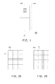
- FIG. 1 is a schematic diagram illustrating a transparent display device according to an embodiment of the invention.
- FIG. 2A to FIG. 2E are schematic diagrams illustrating distribution of pixel areas and transparent areas on a transparent display panel according to an embodiment of the invention.
- FIG. 3A to FIG. 3D are schematic diagrams illustrating pixel arrangement according to an embodiment of the invention.
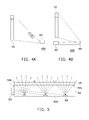
- FIG. 4A and FIG. 4B are schematic diagrams illustrating a transparent display device according to an embodiment of the invention.
- FIG. 5 is a schematic diagram illustrating a transparent display device according to another embodiment of the invention.
- FIG. 1 is a schematic diagram illustrating a transparent display device according to an embodiment of the invention.
- the transparent display device 100 includes a transparent display panel 102 and a transparent backlight unit 104.
- the transparent display panel 102 may be a liquid crystal display (LCD) panel, e.g., a twisted nematic (TN) LCD panel, a vertical alignment (VA) LCD panel, an in-phase switching (IPS) LCD panel, an optically compensated bend (OCB) LCD panel, or a blue phase LCD panel.
- the transparent backlight unit 104 is an OELD display panel in the present embodiment, which should not be construed as a limitation to the invention.
- the transparent display panel 102 adjusts distribution of a non-transparent area on the transparent display panel 102 according to a display data signal D1.
- the transparent backlight unit 104 is configured at one side of the transparent display panel 102, and the transparent backlight unit 104 emits light and acts as a backlight source to irradiate the transparent display panel 102, such that the transparent display panel 102 displays an image through the distribution of the non-transparent area.
- the light emitted by the transparent backlight unit 104 is toward the transparent display panel 102, which should not be construed as a limitation to the invention.
- the light emitted by the transparent backlight unit 104 may face against the transparent display panel 102, or the transparent backlight unit 104 may emit light simultaneously facing toward and against the transparent display panel 102.
- the transparent backlight unit 104 may serve as the backlight source of the transparent display panel 102 without impeding the transparent display device 100 from transparent display.
- the conventional light box is not required for providing the backlight source, and thereby the transparent display device 100 may have the reduced thickness.
- FIG. 2A to FIG. 2E are schematic diagrams illustrating distribution of pixel areas and transparent areas on a transparent display panel according to an embodiment of the invention.
- the transparent display panel 102 may include a plurality of pixel areas PZ1 and a plurality of transparent areas T1.
- the transparent areas T1 may be liquid crystal pixels that are not controlled by the display data signal D1, for instance, or the transparent areas T1 do not have any liquid crystal pixels.
- the transparent areas T1 are constituted merely by transparent substance, e.g., air or optical clear adhesive (OCA).
- OCA optical clear adhesive
- a gray scale level of each of the pixel areas PZ1 is adjusted according to the display data signal D1, such that an image is displayed on the transparent display panel 102.
- the transparent areas T1 are periodically arranged on the transparent display panel 102 and alternately arranged with the pixel areas PZ1.
- the transparency of the transparent areas T1 is not changed together with the display data signal D1, and therefore the arrangement of the transparent areas T1 on the transparent display panel 102 may enhance the transparency of the transparent display device 100.
- the transparency may be determined based on the transmittance or the scattering degree; therefore, the word "transparency" herein may include transmittance (or transmissivity) and haze.
- the transparency of the transparent areas T1 may be changed.
- the pixels may receive transparency control signals through data lines (not shown) and further adjust the transparency of the transparent areas T1.
- the transparency of the transparent display device 100 as a whole may be adjusted.
- a user is allowed to determine the transparency of the transparent display device 100 based on the background environment where the transparent display device 100 is located, and the background may be prevented from affecting the display quality of the display image sensed by the user.
- each of the pixel areas PZ1 includes a plurality of pixels PI, and each of the pixels P1 includes at least one sub-pixel SP1.
- the color of each of the sub-pixels is one of red color, green color, blue color, and yellow color.
- the sub-pixels in different colors may be implemented by a color filter layer.
- the transparent display device 100 may further include a color filter layer configured on the transparent display panel 102.
- the color filter layer has a plurality of pixels P1 corresponding to the pixel areas PZ1, and each of the pixels P1 includes at least one sub-pixel SP1.
- Each of the sub-pixels SP1 is one of a red color filter layer R, a green color filter layer G, a blue color filter layer B, and a yellow color filter layer Y.
- the transparent areas T1 do not have any corresponding color filter layer; in other words, the color filter layer corresponding to the transparent areas T1 is transparent.
- the pixels P1 respectively shown in FIG. 3A and FIG. 3B both include three color filter layers R, G, and B.
- the pixel P1 shown in FIG. 3B further includes a white sub-pixel W which may be formed by not placing any color filter layer on the sub-pixel SP1 or placing a transparent color filter layer on the sub-pixel SP1.
- the difference between the white sub-pixel W and the transparent area T1 lies in that the gray scale level of the white sub-pixel W is changed according to the display data signal D1, while the gray scale level of the transparent area T1 is changed according to the transparency control signal.
- the pixel P1 shown in FIG. 3C includes four color filter layers R, G, B, and Y.
- the transparent display device may display a color image.
- the transparent areas T1 may enhance the transparency of the displayed color image or adjust the transparency of the displayed color image by changing the gray scale levels of the transparent areas T1.
- the sub-pixels SP1 described in the present embodiment are arranged in a stripe manner, which should not be construed as a limitation to the invention.
- the arrangement of sub-pixels SP1 may be in a mosaic shape or in a triangle shape.
- the pixel P1 merely includes the white sub-pixel W, and thus the transparent display device 100 having the sub-pixel W shown in FIG. 3D may only display a black-and-white image.
- the transparent areas T1 are overlapped with the transparent backlight unit 104 in all of the embodiments shown in FIG. 3A to FIG. 3D . That is, the image displayed on the transparent areas T1 is affected by the transparent backlight unit 104. Nonetheless, as described in the embodiments shown in FIG. 2A to FIG. 2E , the transparent areas T1 may be merely constituted by transparent substance, i.e., air or OCA.
- the transparent backlight unit 104 is placed behind the red, green, blue, and yellow sub-pixels, while no transparent backlight unit 104 is placed behind and irradiates the transparent areas T1.
- the transparent display device 100 may clearly display images and may still allow a user to see scenery objects behind the transparent display device 100, and the user's vision to the background scene is not blocked by the light emitted from the transparent backlight unit 104.
- FIG. 4A is a schematic diagram illustrating a transparent display device according to another embodiment of the invention.
- the transparent backlight unit 104 of the transparent display device 400A is implemented in form of a projection unit 402.
- the projection unit 402 may sequentially project light in red, blue, and green through applying a color sequential method, so as to produce full-color composite images in human brains on account of vision persistence of human beings.
- FIG. 4B is a schematic diagram illustrating a transparent display device according to another embodiment of the invention. As shown in FIG.
- the transparent display device 400B may further include a reflective unit that reflects projection light of the projection unit 402 and acts as the backlight source. Thereby, the user is also able to observe color images.
- the transparent display panel 102 may be irradiated more evenly, and the display quality of the image can be further ameliorated.
- one single pixel area PZ1 corresponds to one single transparent area T1, which should not be construed as a limitation to the invention.
- plural pixel areas PZ1 may correspond to one transparent area T1, or one pixel area PZ1 corresponds to plural transparent areas T1, and thereby the transparency control and the display contents may become diverse and profound.
- FIG. 5 is a schematic diagram illustrating a transparent display device according to another embodiment of the invention.
- the transparent backlight unit 104 of the transparent display device 500 may be implemented in form of the light source 502 and the LGP 504.
- the LGP 504 has a light-incident side surface 504a, a first surface 504b, and a second surface 504c opposite to the first surface 504b, and the second surface 504c is located between the transparent display panel 102 and the first surface 504b.
- the light source 502 is configured adjacent to the light-incident side surface 504a of the LGP 504, and the first surface 504b of the LGP 504 has a plurality of scattering particles 506 thereon.
- the scattering particles 506 may reflect light emitted from the light source 502 and serve as the backlight source.
- the area of the display image occupied by the scattering particles 506 is rather insignificant; thus, when a user observes the display image on the transparent display device 500, the user is not able to perceive the scattering particles 506. That is, in the user's eyes, the display image on the transparent display device 500 appears to be a transparent display image.
- the transparent backlight unit serves as the backlight source of the transparent display panel in an embodiment of the invention, such that the transparent display device may have the reduced thickness.
- the transparent areas on the transparent display panel may enhance the transparency of the transparent display device.
- the transparency of the transparent display device may be changed, and thereby the readability of images displayed on the transparent display device may be improved.
Landscapes
- Physics & Mathematics (AREA)
- Nonlinear Science (AREA)
- General Physics & Mathematics (AREA)
- Chemical & Material Sciences (AREA)
- Crystallography & Structural Chemistry (AREA)
- Engineering & Computer Science (AREA)
- Mathematical Physics (AREA)
- Geometry (AREA)
- Optics & Photonics (AREA)
- Computer Hardware Design (AREA)
- Theoretical Computer Science (AREA)
- Control Of Indicators Other Than Cathode Ray Tubes (AREA)
- Liquid Crystal Display Device Control (AREA)
Applications Claiming Priority (1)
| Application Number | Priority Date | Filing Date | Title |
|---|---|---|---|
| TW101118966A TW201348816A (zh) | 2012-05-28 | 2012-05-28 | 透明顯示裝置 |
Publications (1)
| Publication Number | Publication Date |
|---|---|
| EP2669735A1 true EP2669735A1 (fr) | 2013-12-04 |
Family
ID=48625726
Family Applications (1)
| Application Number | Title | Priority Date | Filing Date |
|---|---|---|---|
| EP13168573.7A Withdrawn EP2669735A1 (fr) | 2012-05-28 | 2013-05-21 | Dispositif d'affichage transparent |
Country Status (3)
| Country | Link |
|---|---|
| US (1) | US20130314452A1 (fr) |
| EP (1) | EP2669735A1 (fr) |
| TW (1) | TW201348816A (fr) |
Cited By (5)
| Publication number | Priority date | Publication date | Assignee | Title |
|---|---|---|---|---|
| WO2015119453A1 (fr) | 2014-02-07 | 2015-08-13 | Samsung Electronics Co., Ltd. | Affichage en mode double |
| US10375365B2 (en) | 2014-02-07 | 2019-08-06 | Samsung Electronics Co., Ltd. | Projection system with enhanced color and contrast |
| US10453371B2 (en) | 2014-02-07 | 2019-10-22 | Samsung Electronics Co., Ltd. | Multi-layer display with color and contrast enhancement |
| US10554962B2 (en) | 2014-02-07 | 2020-02-04 | Samsung Electronics Co., Ltd. | Multi-layer high transparency display for light field generation |
| US10565925B2 (en) | 2014-02-07 | 2020-02-18 | Samsung Electronics Co., Ltd. | Full color display with intrinsic transparency |
Families Citing this family (9)
| Publication number | Priority date | Publication date | Assignee | Title |
|---|---|---|---|---|
| US20160178979A1 (en) * | 2013-03-07 | 2016-06-23 | Sharp Kabushiki Kaisha | Liquid crystal display device |
| CN103617777B (zh) | 2013-11-28 | 2016-07-06 | 京东方科技集团股份有限公司 | 阵列基板、彩膜基板及制造方法、显示面板 |
| KR102389626B1 (ko) * | 2014-12-11 | 2022-04-25 | 삼성디스플레이 주식회사 | 표시 패널 및 표시 패널을 포함하는 유기 발광 표시 장치 |
| US9666118B2 (en) | 2015-10-01 | 2017-05-30 | Chunghwa Picture Tubes, Ltd. | Transparent display apparatus |
| CN106128375B (zh) * | 2016-06-24 | 2018-11-23 | 深圳市华星光电技术有限公司 | 透明液晶显示器的数据处理方法 |
| CN106462019B (zh) * | 2016-08-30 | 2019-07-05 | 京东方科技集团股份有限公司 | 液晶显示面板及其控制方法、液晶显示装置 |
| CN106842677B (zh) * | 2016-12-26 | 2018-07-03 | 深圳市华星光电技术有限公司 | 一种透明液晶显示面板及包含其的显示器 |
| TWI629675B (zh) * | 2017-08-18 | 2018-07-11 | Industrial Technology Research Institute | 影像辨識系統及其資訊顯示方法 |
| CN112859405B (zh) * | 2021-01-18 | 2024-04-12 | 京东方科技集团股份有限公司 | 透明显示模组和透明显示装置 |
Citations (3)
| Publication number | Priority date | Publication date | Assignee | Title |
|---|---|---|---|---|
| EP2026571A2 (fr) * | 2007-08-08 | 2009-02-18 | Hitachi Ltd. | Appareil d'affichage à cristaux liquides et unité de projection arrière, et appareil de tableau noir électronique avec un appareil d'affichage à cristaux liquides |
| KR20090122023A (ko) * | 2008-05-23 | 2009-11-26 | 한국과학기술원 | 투명 유기발광다이오드 백라이트 유닛 및 이를 이용한 투명풀컬러 액정 디스플레이 |
| CN102402083A (zh) * | 2011-08-29 | 2012-04-04 | 友达光电股份有限公司 | 像素结构、液晶显示面板与透明液晶显示器 |
Family Cites Families (3)
| Publication number | Priority date | Publication date | Assignee | Title |
|---|---|---|---|---|
| US7057594B1 (en) * | 1995-08-22 | 2006-06-06 | The United States Of America As Represented By The Secretary Of The Navy | Reconfigurable liquid crystal display |
| US8770813B2 (en) * | 2010-12-23 | 2014-07-08 | Microsoft Corporation | Transparent display backlight assembly |
| US20120162269A1 (en) * | 2010-12-23 | 2012-06-28 | Microsoft Corporation | Transparent Display Active Backlight |
-
2012
- 2012-05-28 TW TW101118966A patent/TW201348816A/zh unknown
-
2013
- 2013-03-14 US US13/802,798 patent/US20130314452A1/en not_active Abandoned
- 2013-05-21 EP EP13168573.7A patent/EP2669735A1/fr not_active Withdrawn
Patent Citations (4)
| Publication number | Priority date | Publication date | Assignee | Title |
|---|---|---|---|---|
| EP2026571A2 (fr) * | 2007-08-08 | 2009-02-18 | Hitachi Ltd. | Appareil d'affichage à cristaux liquides et unité de projection arrière, et appareil de tableau noir électronique avec un appareil d'affichage à cristaux liquides |
| KR20090122023A (ko) * | 2008-05-23 | 2009-11-26 | 한국과학기술원 | 투명 유기발광다이오드 백라이트 유닛 및 이를 이용한 투명풀컬러 액정 디스플레이 |
| CN102402083A (zh) * | 2011-08-29 | 2012-04-04 | 友达光电股份有限公司 | 像素结构、液晶显示面板与透明液晶显示器 |
| US20130050618A1 (en) * | 2011-08-29 | 2013-02-28 | Wen-Bin Lo | Pixel structure, liquid crystal display panel and transparent liquid crystal display device |
Cited By (7)
| Publication number | Priority date | Publication date | Assignee | Title |
|---|---|---|---|---|
| WO2015119453A1 (fr) | 2014-02-07 | 2015-08-13 | Samsung Electronics Co., Ltd. | Affichage en mode double |
| US10375365B2 (en) | 2014-02-07 | 2019-08-06 | Samsung Electronics Co., Ltd. | Projection system with enhanced color and contrast |
| US10380933B2 (en) | 2014-02-07 | 2019-08-13 | Samsung Electronics Company, Ltd. | Display with high transparency |
| US10453371B2 (en) | 2014-02-07 | 2019-10-22 | Samsung Electronics Co., Ltd. | Multi-layer display with color and contrast enhancement |
| US10554962B2 (en) | 2014-02-07 | 2020-02-04 | Samsung Electronics Co., Ltd. | Multi-layer high transparency display for light field generation |
| US10565925B2 (en) | 2014-02-07 | 2020-02-18 | Samsung Electronics Co., Ltd. | Full color display with intrinsic transparency |
| EP3103110B1 (fr) * | 2014-02-07 | 2020-10-28 | Samsung Electronics Co., Ltd. | Affichage en mode double |
Also Published As
| Publication number | Publication date |
|---|---|
| TW201348816A (zh) | 2013-12-01 |
| US20130314452A1 (en) | 2013-11-28 |
Similar Documents
| Publication | Publication Date | Title |
|---|---|---|
| US20130314452A1 (en) | Transparent dispay device | |
| CN103487989A (zh) | 透明显示装置 | |
| KR102670532B1 (ko) | 광 밸브를 구비한 액정 표시장치 | |
| JP5610977B2 (ja) | ディスプレイ制御装置 | |
| CN101059619B (zh) | 液晶显示器件 | |
| US7528893B2 (en) | Backlight for liquid crystal display | |
| US9075255B2 (en) | Display device | |
| US20110273636A1 (en) | Embedded stereoscopic 3d display and 2d display film stack | |
| US20160048058A1 (en) | Liquid crystal panel and liquid crystal display | |
| KR20210016638A (ko) | 혼합형 백라이트, 디스플레이, 및 방법 | |
| KR20210097815A (ko) | 동적 컬러 서브 픽셀들 리맵핑을 갖는 멀티뷰 디스플레이, 시스템 및 방법 | |
| US11126027B2 (en) | Display apparatus and driving method thereof | |
| US9507168B2 (en) | Stereoscopic image display having pattern groove | |
| JP2006330610A (ja) | 三次元表示装置 | |
| JP2012032611A (ja) | 立体画像表示装置 | |
| US8576141B2 (en) | Three-dimensional display device and image presentation method | |
| KR102635499B1 (ko) | 표시 장치 | |
| US7349156B2 (en) | Display device for displaying three-dimensional image | |
| JP5131331B2 (ja) | 液晶表示装置 | |
| CN205404970U (zh) | 一种2d/3d切换显示装置 | |
| JP2007017768A (ja) | 表示装置 | |
| US20180081183A1 (en) | 2d/3d switchable display device | |
| US20130293794A1 (en) | Liquid crystal display panel and liquid crystal display apparatus and 3d image system | |
| US20180341149A1 (en) | Transparent liquid crystal display panel and display device comprising the same | |
| CN117724272A (zh) | 空间光调制器及全息三维显示设备 |
Legal Events
| Date | Code | Title | Description |
|---|---|---|---|
| PUAI | Public reference made under article 153(3) epc to a published international application that has entered the european phase |
Free format text: ORIGINAL CODE: 0009012 |
|
| AK | Designated contracting states |
Kind code of ref document: A1 Designated state(s): AL AT BE BG CH CY CZ DE DK EE ES FI FR GB GR HR HU IE IS IT LI LT LU LV MC MK MT NL NO PL PT RO RS SE SI SK SM TR |
|
| AX | Request for extension of the european patent |
Extension state: BA ME |
|
| STAA | Information on the status of an ep patent application or granted ep patent |
Free format text: STATUS: THE APPLICATION IS DEEMED TO BE WITHDRAWN |
|
| 18D | Application deemed to be withdrawn |
Effective date: 20140605 |