EP2669840B1 - Verschlüsselungstastatur - Google Patents
Verschlüsselungstastatur Download PDFInfo
- Publication number
- EP2669840B1 EP2669840B1 EP13179754.0A EP13179754A EP2669840B1 EP 2669840 B1 EP2669840 B1 EP 2669840B1 EP 13179754 A EP13179754 A EP 13179754A EP 2669840 B1 EP2669840 B1 EP 2669840B1
- Authority
- EP
- European Patent Office
- Prior art keywords
- key
- main control
- control board
- panel
- flexible circuit
- Prior art date
- Legal status (The legal status is an assumption and is not a legal conclusion. Google has not performed a legal analysis and makes no representation as to the accuracy of the status listed.)
- Not-in-force
Links
Images


Classifications
-
- G—PHYSICS
- G06—COMPUTING OR CALCULATING; COUNTING
- G06F—ELECTRIC DIGITAL DATA PROCESSING
- G06F21/00—Security arrangements for protecting computers, components thereof, programs or data against unauthorised activity
- G06F21/70—Protecting specific internal or peripheral components, in which the protection of a component leads to protection of the entire computer
- G06F21/82—Protecting input, output or interconnection devices
- G06F21/83—Protecting input, output or interconnection devices input devices, e.g. keyboards, mice or controllers thereof
-
- G—PHYSICS
- G07—CHECKING-DEVICES
- G07F—COIN-FREED OR LIKE APPARATUS
- G07F19/00—Complete banking systems; Coded card-freed arrangements adapted for dispensing or receiving monies or the like and posting such transactions to existing accounts, e.g. automatic teller machines
- G07F19/20—Automatic teller machines [ATMs]
- G07F19/205—Housing aspects of ATMs
-
- G—PHYSICS
- G07—CHECKING-DEVICES
- G07F—COIN-FREED OR LIKE APPARATUS
- G07F7/00—Mechanisms actuated by objects other than coins to free or to actuate vending, hiring, coin or paper currency dispensing or refunding apparatus
- G07F7/08—Mechanisms actuated by objects other than coins to free or to actuate vending, hiring, coin or paper currency dispensing or refunding apparatus by coded identity card or credit card or other personal identification means
- G07F7/10—Mechanisms actuated by objects other than coins to free or to actuate vending, hiring, coin or paper currency dispensing or refunding apparatus by coded identity card or credit card or other personal identification means together with a coded signal, e.g. in the form of personal identification information, like personal identification number [PIN] or biometric data
-
- G—PHYSICS
- G07—CHECKING-DEVICES
- G07F—COIN-FREED OR LIKE APPARATUS
- G07F7/00—Mechanisms actuated by objects other than coins to free or to actuate vending, hiring, coin or paper currency dispensing or refunding apparatus
- G07F7/08—Mechanisms actuated by objects other than coins to free or to actuate vending, hiring, coin or paper currency dispensing or refunding apparatus by coded identity card or credit card or other personal identification means
- G07F7/10—Mechanisms actuated by objects other than coins to free or to actuate vending, hiring, coin or paper currency dispensing or refunding apparatus by coded identity card or credit card or other personal identification means together with a coded signal, e.g. in the form of personal identification information, like personal identification number [PIN] or biometric data
- G07F7/1025—Identification of user by a PIN code
- G07F7/1033—Details of the PIN pad
-
- H—ELECTRICITY
- H01—ELECTRIC ELEMENTS
- H01H—ELECTRIC SWITCHES; RELAYS; SELECTORS; EMERGENCY PROTECTIVE DEVICES
- H01H2223/00—Casings
- H01H2223/002—Casings sealed
-
- Y—GENERAL TAGGING OF NEW TECHNOLOGICAL DEVELOPMENTS; GENERAL TAGGING OF CROSS-SECTIONAL TECHNOLOGIES SPANNING OVER SEVERAL SECTIONS OF THE IPC; TECHNICAL SUBJECTS COVERED BY FORMER USPC CROSS-REFERENCE ART COLLECTIONS [XRACs] AND DIGESTS
- Y04—INFORMATION OR COMMUNICATION TECHNOLOGIES HAVING AN IMPACT ON OTHER TECHNOLOGY AREAS
- Y04S—SYSTEMS INTEGRATING TECHNOLOGIES RELATED TO POWER NETWORK OPERATION, COMMUNICATION OR INFORMATION TECHNOLOGIES FOR IMPROVING THE ELECTRICAL POWER GENERATION, TRANSMISSION, DISTRIBUTION, MANAGEMENT OR USAGE, i.e. SMART GRIDS
- Y04S40/00—Systems for electrical power generation, transmission, distribution or end-user application management characterised by the use of communication or information technologies, or communication or information technology specific aspects supporting them
- Y04S40/20—Information technology specific aspects, e.g. CAD, simulation, modelling, system security
Definitions
- the present invention relates to an encryption keyboard, and in particular, to an encryption keyboard with a detection and protection system against frontal probing.
- Hardware encryption keyboards of self-serving banking terminals are responsible for handling users' banking passwords inputting and encryption processing.
- working keys and master keys of the banks are stored in core processing components of the keyboards.
- Those who with unlawful purposes may pry or probe into the keyboards to capture user passwords, or even to read working keys and master keys of the banks, in order to steal documents from the banks, putting the documents and money of users and banks at risk.
- US 2009/0184850 A1 relates to secure keypad devices and to data entry devices having anti-tamper functionality.
- a key mat is disclosed with a plurality of depressible keys, which partially extend through key apertures and a flexible protective partial enclosure including an anti-tampering grid coupled to an anti-tampering detection circuitry.
- US 2009/0094700 A1 relates to an information processing apparatus that makes it difficult to unlawfully take out information and notifies of any unlawful action by immediately detecting it if any.
- a pressure-sensing conductive rubber connector is disclosed for sensing abnormalities of a compression force within a housing case and a housing cover.
- EP 1873680 A1 relates to a card reader comprising a contacting unit disposed in a pocket in order to protect it against manipulation.
- An electrical connection between contact surfaces and corresponding counter contacts of a customer's printed circuit board is established e.g. using an intermediate electrically conducting rubber.
- WO 2005/001673 A1 relates to the field of copy protection of digital content. Multiple portions of memory provided in a storage module are disclosed, wherein after unauthorized use is detected access to the information is prevented by blank erasing a private key required for decrypting or by blank erasing a table of contents.
- CN 2603436 Y relates to a waterproof keyboard covered with a transparent silicone rubber layer.
- GB 2178242 A relates to a coordinate graphic input tablet comprising transparent and electrically insulating material such as silicone rubbers for making substrate sheets.
- transparent and electrically insulating material such as silicone rubbers for making substrate sheets.
- a rigid lining plate is provided on the flexible substrate sheet.
- US 2003/0201983 A1 discloses a keymat for a mobile station or similar device that can be easily removed and reinstalled, allowing a mobile station user to exchange the keymat for another.
- the exchangeable keymat is installed on the exterior surface of the mobile station, and the mobile station has retaining means to removably retain the keymat so as to remain the keymat in place for mobile-station operation.
- US 2006/0102458 A1 relates to an apparatus for entering a Personal Identification Number in a cash transaction machine.
- a key module is disclosed including pluralities of buttons, a transmitting member and a switching member at the rear of the transmitting member. The rear of the button presses a groove formed on the front of the transmitting member.
- a pair of screw holes for a screw for coupling the key module and a rear case is formed on a vertical line passing the center portion.
- encryption keyboards include a probing detection and protection structure, and a probing detection and protection circuit.
- the probing detection and protection circuit When physical probing is initiated to a keyboard, the probing detection and protection circuit outputs a self-destruct signal, to enable a self-destruct function of the encryption keyboard, thereby preventing the bad guys from stealing the documents.
- a conventional encryption keyboard includes: a keyboard panel 1, a lining plate 2, keys 3, a water-resistant silica gel layer 4, a main control board 8, and a bottom plate 9.
- the keyboard is assembled by stacking up these components in sequence. Due to lack of a protective structure in front of the keyboard, the main control board 8 may easily be accessible to the bad guys if they have some of the components 1 to 4 damaged. In this manner, information in the circuit of the main control board can be obtained, and information that is crucial to the safe use of the self-serving terminals, e.g., user inputted passwords, may be stolen.
- An object of the invention is to provide an encryption keyboard with a detection and protection system against frontal probing, which effectively prevents illegal probing for password information from the front of the keyboard panel.
- the invention provides the following technical solution.
- An encryption keyboard includes a panel and a main control board.
- a sealed flexible circuit board is provided between the panel and the main control board.
- An anti-probing detection circuit is provided in the sealed flexible circuit board.
- the anti-probing detection circuit is connected to a surface of the sealed flexible circuit board via a circuit pin, and electrical connection is formed via the circuit pin between the anti-probing detection circuit and a control circuit of the main control board which implements a self-destruct function.
- a backing plate is provided between the sealed flexible circuit board and the main control board.
- a through-hole is formed in the backing plate correspondingly to the circuit pin.
- the through-hole is adapted to contain conductive rubber.
- the electrical connection between the anti-probing detection circuit and the control circuit of the main control board which implements the self-destruct function is formed via the circuit pin by the conductive rubber.
- a water-resistant silica gel plate is provided between the panel and the sealed flexible circuit board.
- the encryption keyboard further includes a lining plate.
- the lining plate is arranged between the panel and the water-resistant silica gel plate.
- a plurality of key holes are formed on the panel, the lining plate, the water-resistant silica gel plate, the sealed flexible circuit board and the backing plate.
- a plurality of keys are mounted in the key holes.
- Each of the keys includes a key cap and a push rod.
- the push rod includes a first end connecting with the key cap, and a second end penetrating through the key hole to contact with and push a key contact on the main control board.
- the key cap includes a cap top, and a container on the lower surface of the cap top and having a downward opening. The key cap joins with the first end of the push rod via the container, and the first end of the push rod has a diameter smaller than an inner diameter of the container.
- an umbrella-shaped structure which joins between the first end and the second end of the push rod.
- the umbrella-shaped structure has a diameter larger than a diameter of the key hole on the sealed flexible circuit board.
- the second end of the push rod has a diameter smaller than the diameter of the key hole, and larger than a diameter of a package structure of the key contact on the main control board.
- the key cap is made of stainless steel
- the push rod is made of heat-treated steel grade 45 having a hardness larger than 45.
- the encryption keyboard further includes a bottom plate.
- Welded bolts for packaging the keyboard are provided on the panel of the encryption keyboard.
- Through-holes for holding the welded bolts are provided on the lining plate, the water-resistant silica gel plate, the sealed flexible circuit board, the backing plate, the main control board and the bottom plate correspondingly to the welded bolts on the panel.
- the lining plate, the water-resistant silica gel plate, the sealed flexible circuit board, the backing plate, the main control board and the bottom plate are mounted on the welded bolts sequentially, and are fastened with corresponding nuts.
- the number of the welded bolts is nine. Eight of the bolts are arranged along the four edges of the keyboard panel, with each edge having two blots.
- the ninth bolt is arranged in the middle of the encryption keyboard, and the conductive rubber is arranged near the ninth welded bolt.
- a sealed flexible circuit board is provided between the keyboard panel and the main control board.
- the sealed flexible circuit board covers the whole main control board, so that illegal probing from the front of the keyboard panel can be detected by its internal anti-probing detection circuit while meeting the flexible circuit board, which activates the self-destruct of the encryption keyboard.
- each of the keys includes a key cap and a push rod;
- the push rod includes a first end connecting with the key cap, and a second end penetrating through the key hole to contact with and push a key contact on the main control board;
- the key cap includes a cap top, and a container on the lower surface of the cap top and having a downward opening;
- the key cap joins with the first end of the push rod via the container, and the first end of the push rod has a diameter smaller than an inner diameter of the container, therefore, a gap is formed between the push rod and the cap top.
- the gap may make things slippery, it may trouble the bad guys while they are trying to probe into the key cap from its front, thereby preventing probing.
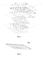
- An encryption keyboard 100 provided by the invention includes: a keyboard panel 1, a lining plate 2, keys 3, a water-resistant silica gel plate 4, a sealed flexible circuit board 5, a backing plate 6, conductive rubber 7, a main control board 8 and a bottom plate 9. The components above 1 to 9 are assembled sequentially to form the encryption keyboard 100.
- the casing of the key 3 has a structure including two steps (31, 32). Correspondingly, key through-holes (11, 21) are formed on the keyboard panel 1 and the lining plate 2 respectively.
- the size of the key through-hole 11 of the keyboard panel 1 is slightly larger than the size of the key step 31, so that the key 3 can be positioned by the keyboard panel 1 and packaged on the main control board 8.
- Welded bolts 12 for packaging the keyboard are provided on the keyboard panel 1.
- Through-holes for holding the bolts 12 are provided on the lining plate 2, the water-resistant silica gel plate 4, the sealed flexible circuit board 5, the backing plate 6, the main control board 8 and the bottom plate 9 correspondingly to the welded bolts 12 on the keyboard panel 1.
- the lining plate 2, the water-resistant silica gel plate 4, the sealed flexible circuit board 5, the backing plate 6, the main control board 8 and the bottom plate 9 are mounted on the welded bolts 12 sequentially, and then fastened with nuts 10.
- the water-resistant silica gel plate 4 is arranged between the layer of keys 3 and the main control board 8, preventing water and dust from entering the encryption keyboard 100 through the key holes on the keyboard panel 1 and the lining plate 2, and preventing their effects or damages to the circuit on the main control board 8 which may further lead to abandonment of the whole encryption keyboard 100.
- the sealed flexible circuit board 5 and the backing plate 6 are arranged between the water-resistant silica gel plate 4 and the main control board 8.
- An anti-probing detection circuit (not shown) is provided in the sealed flexible circuit board 5.
- the anti-probing detection circuit is connected to the surface of the sealed flexible circuit board 5 via a circuit pin 51, and is electrically connected with a control circuit (not shown) of the main control board by conductive rubber 7.
- the sealed flexible circuit board 5 fully covers the main control board in front of the encryption keyboard, effectively preventing probing initiated from the front of the encryption keyboard 100. Once the probing from the front of the encryption keyboard 100 meets the sealed flexible circuit board 5 anywhere, the anti-probing detection circuit is activated.
- the anti-probing detection circuit transmits a signal to the control circuit of the main control board 8 via the circuit pin 51 and the conductive rubber 7.
- the control circuit outputs a keyboard self-destruct instruction, completely destroying the encryption keyboard, thereby protecting the frontal panel from being probed into, and greatly increasing the security of the encryption keyboard.
- the number of the bolts 12 for packaging the keyboard welded on the keyboard panel 1 is nine, eight of which are arranged along the four edges of the keyboard with each edge having two blots, and the ninth one is arranged in the middle of the encryption keyboard.
- the conductive rubber 7 is arranged near the ninth bolt. Positioned with the help of the welded bolt, the conductive rubber 7 ensures that the circuit pin 51 on the sealed flexible circuit board 5 is precisely aligned with the circuit pin of the main control board 8.
- the conductive rubber 7 can maintain a good force-bearing state, so that when the encryption keyboard 100 is assembled, the circuit pin 51 on the sealed flexible circuit board 5, the conductive rubber 7 and the circuit pin of the main control board 8 can be pushed in place; and once being illegally loosened, the encryption keyboard 100 can self-destruct.
- a through-hole 61 is formed on the backing plate 6 correspondingly to the circuit pin 51.
- the through-hole 61 may contain the conductive rubber 7 and position the conductive rubber 7, so that precise positioning of the circuit pin 51 on the sealed flexible circuit board 5, the conductive rubber 7 and the circuit pin of the main control board 8 is guaranteed.
- the sealed flexible circuit board 5 can only be pressed for a limited number of times, which is far less than the 1,000,000 requirement for keys. Therefore, through-holes 52 and 62 are formed on the sealed flexible circuit board 5 and the backing plate 6 correspondingly to the key 3 and a push rod 33 respectively. As shown in Fig. 3 and Fig. 4 , the key 3 goes through the through-holes 52 and 62 and directly pushes a key contact on the main control board 8. Due to the presence of the through-hole 52, the sealed flexible circuit board 5 no longer fully covers the main control board 8, resulting in areas vulnerable to frontal probing to the encryption keyboard. If a probing attack is directed downwards from a key, it may dodge the detection of the sealed flexible circuit board 5 and easily reach the main control board 8. With some techniques such as disguise, user passwords may be captured, causing a great safety risk.
- the invention further provides a detachable key 3.
- the key 3 includes a key cap 34 and a push rod 35.
- the key cap 34 includes a cap top 341, and a container 342 on the lower surface of the cap top 341 and having a downward opening.
- the push rod 35 includes a first end 351 and a second end 352.
- the key cap 34 joins with the first end 351 of the push rod 35 via the container 342, and the diameter of the first end 341 is slightly smaller than the inner diameter of the container 342. Therefore, a gap is formed between the first end 351 of the push rod 35 and the walls 343 of the container 342.
- an umbrella-shaped structure 353 is provided, which joins between the first end 351 and the second end 352 of the push rod 35.
- the diameter of the umbrella-shaped structure 353 is larger than the diameter of the key through-holes 52 and 62 on the sealed flexible circuit board 5 and the backing plate 6.
- the second end 352 of the push rod is normally designed to have a diameter d0 smaller than the diameter of the through-holes 52 and 62, but larger than the diameter of the package structure of the key contact on the main control board. Therefore, when the key is pressed sideways and its bottom is slightly shifted, an elastic member of the key contact can be pressed smoothly.
- the key cap 34 of the key 3 may be made of stainless steel, and the push rod may be made of heat-treated 45# steel having a HRC hardness higher than 45, which protects the keys from being probed into or broken from the material perspective.
- the diameter D of the umbrella-shaped structure is set to a proper value, which ensures that the diameter H of the circular area formed by the intersection of the area with the angle A and the upper plane of the main control board 8 is larger than the diameter of the through-hole 52 on the flexible circuit board 5, the area with the angle A being defined by the extreme positions where the umbrella-shaped structure can be probed into from the exposed surface of the key 3.
- the key 3 while the key 3 is being probed sideways from its exposed surface: if it is probed from outside the area with the angle A, once the flexible circuit board 5 is reached, a break in any line of the circuit or a short circuit between any two adjacent lines of the circuit may produce a self-destruct signal, causing the keyboard to self-destruct and thereby providing good protection; and if the key 3 is probed from within the area with the angle A, it can not be broken through due to the slipperiness of the push rod 35, thereby protecting the main control board 8 and protecting user passwords from being stolen.
Landscapes
- Physics & Mathematics (AREA)
- General Physics & Mathematics (AREA)
- Engineering & Computer Science (AREA)
- Computer Hardware Design (AREA)
- Theoretical Computer Science (AREA)
- General Engineering & Computer Science (AREA)
- Software Systems (AREA)
- Computer Security & Cryptography (AREA)
- Business, Economics & Management (AREA)
- Accounting & Taxation (AREA)
- Finance (AREA)
- Input From Keyboards Or The Like (AREA)
- Push-Button Switches (AREA)
Claims (6)
- Verschlüsselungstastatur mit einer Blende (1) und einer Hauptsteuerplatine (8), wobei:eine versiegelte flexible Leiterplatte (5) zwischen der Blende (1) und der Hauptsteuerplatine (8) vorgesehen ist;ein Eindringverhinderungs- bzw. -Erfassungsschaltkreis in der versiegelten flexiblen Leiterplatte (5) vorgesehen ist;und der Endringverhinderungs-Erfassungsschaltkreis über einen Schaltungsstift (51) an eine Oberfläche der versiegelten flexiblen Leiterplatte (5) angeschlossen und über den Schaltungsstift (51) zwischen dem Endringverhinderungs- bzw. -Erfassungsschaltkreis und einer Steuerschaltung der Hauptsteuerplatine (8) eine elektrische Verbindung gebildet ist, wodurch eine Selbstzerstörungsfunktion verwirklicht ist; und eine Zusatzplatte (6) zwischen der versiegelten flexiblen Leiterplatte (5) und der Hauptsteuerplatine (8) vorgesehen ist; eine Durchgangsöffnung (61) in der Zusatzplatte (6) entsprechend dem Schaltungsstift (51) gebildet ist; und die Durchgangsöffnung (61) so eingerichtet ist, dass sie ein leitfähiges Gummiteil (7) enthält, und die elektrische Verbindung zwischen dem Eindringverhinderungs- bzw. -Erfassungsschaltkreis und der Steuerschaltung der Hauptsteuerplatine (8), die die Selbstzerstörungsfunktion bereitstellt, über den Schaltungsstift (51) durch das leitfähige Gummiteil (7) gebildet ist; undeine wasserbeständige Silicagelplatte (4) zwischen der Blende (1) und der versiegelten flexiblen Leiterplatte (5) vorgesehen ist; unddie Verschlüsselungstastatur darüber hinaus eine Kaschierungsplatte (2) zwischen der Blende (1) und der wasserbeständigen Silicagelplatte (4) aufweist; mehrere Tastenöffnungen (11, 21, 52, 62) an der Blende (1), der Kaschierungsplatte (2), der wasserbeständigen Silicagelplatte (4), der versiegelten flexiblen Leiterplatte (5) und der Zusatzplatte (6) gebildet sind; mehrere Tasten (3) in die Tastenöffnungen (11, 21, 52, 62) eingesetzt sind; jede der Tasten (3) eine Tastenkappe (34) und einen Druckansatz (35) aufweist, wobei der Druckansatz (35) ein erstes Ende (351), das mit der Tastenkappe (34) verbunden ist, und ein zweites Ende (352) aufweist, das sich durch eine Tastenöffnung (11, 21, 52, 62) erstreckt, um einen Kontakt mit einem Tastenkontakt auf der Hauptsteuerplatine (8) herzustellen und gegen diesen zu drücken; wobei die Tastenkappe (34) eine Kappenoberseite (341) und eine Aufnahme (342) an der Unterseite der Kappenoberseite (341) aufweist, die eine nach unten gerichtete Öffnung hat; und die Tastenkappe (34) mit dem ersten Ende (351) des Druckansatzes (35) über die Aufnahme (342) verbunden ist, und das erste Ende (351) des Druckansatzes (35) einen Durchmesser hat, der kleiner ist als der Innendurchmesser der Aufnahme (342).
- Verschlüsselungstastatur nach Anspruch 1, wobei eine regenschirmförmige Struktur (353) vorgesehen ist, die eine Verbindung zwischen dem ersten Ende (351) und dem zweiten Ende (352) des Druckansatzes (35) herstellt; und die regenschirmförmige Struktur (353) einen größeren Durchmesser als die Tastenöffnung (11, 21, 52, 62) hat.
- Verschlüsselungstastatur nach Anspruch 2, wobei das zweite Ende (352) des Druckansatzes (35) einen kleineren Durchmesser als die Tastenöffnung (11, 21, 52, 62) hat und einen größeren Durchmesser als eine Gehäusestruktur des Tastenkontakts an der Hauptsteuerplatine (8) aufweist.
- Verschlüsselungstastatur nach Anspruch 3, wobei die Tastenkappe (34) aus rostfreiem Stahl hergestellt ist und der Druckansatz (35) aus einem wärmebehandelten Stahl der Sorte 45 mit einer Härte von über 45 besteht.
- Verschlüsselungstastatur nach Anspruch 4, wobei:die Verschlüsselungstastatur darüber hinaus eine Grundplatte (9) aufweist;Schweißbolzen (12) zum Zusammensetzen der Tastatur an der Blende (1) der Verschlüsselungstastatur vorgesehen sind;Durchgangsöffnungen zum Aufnehmen der Schweißbolzen (12) an der Kaschierungsplatte (2), der wasserbeständigen Silicagelplatte (4), der versiegelten flexiblen Leiterplatte (5), der Zusatzplatte (6), der Hauptsteuerplatine (8) und der Grundplatte (9) entsprechend den Schweißbolzen (12) an der Blende (1) vorgesehen sind; unddie Kaschierungsplatte (2), die wasserbeständige Silicagelplatte (4), die versiegelte flexible Leiterplatte (5), die Zusatzplatte (6), die Hauptsteuerplatine (8) und die Grundplatte (9) nacheinander auf die Schweißbolzen (12) gesetzt und mit entsprechenden Muttern (10) befestigt sind.
- Verschlüsselungstastatur nach Anspruch 5, wobei
neun Schweißbolzen (12) vorgesehen sind;
acht Bolzen (12) entlang den vier Rändern der Tastaturblende (1) angeordnet sind, wobei jeder Rand zwei Bolzen (12) aufweist; und
der neunte Bolzen (12) in der Mitte der Blende (1) der Verschlüsselungstastatur angeordnet ist und das leitfähige Gummiteil (7) nahe dem neunten Bolzen (12) angeordnet ist.
Applications Claiming Priority (2)
| Application Number | Priority Date | Filing Date | Title |
|---|---|---|---|
| CN2009101928543A CN101697182B (zh) | 2009-09-29 | 2009-09-29 | 一种加密键盘 |
| EP10819848.2A EP2472427A4 (de) | 2009-09-29 | 2010-08-19 | Verschlüsselungstastatur |
Related Parent Applications (2)
| Application Number | Title | Priority Date | Filing Date |
|---|---|---|---|
| EP10819848.2 Division | 2010-08-19 | ||
| EP10819848.2A Division EP2472427A4 (de) | 2009-09-29 | 2010-08-19 | Verschlüsselungstastatur |
Publications (2)
| Publication Number | Publication Date |
|---|---|
| EP2669840A1 EP2669840A1 (de) | 2013-12-04 |
| EP2669840B1 true EP2669840B1 (de) | 2015-02-18 |
Family
ID=42142286
Family Applications (2)
| Application Number | Title | Priority Date | Filing Date |
|---|---|---|---|
| EP10819848.2A Withdrawn EP2472427A4 (de) | 2009-09-29 | 2010-08-19 | Verschlüsselungstastatur |
| EP13179754.0A Not-in-force EP2669840B1 (de) | 2009-09-29 | 2010-08-19 | Verschlüsselungstastatur |
Family Applications Before (1)
| Application Number | Title | Priority Date | Filing Date |
|---|---|---|---|
| EP10819848.2A Withdrawn EP2472427A4 (de) | 2009-09-29 | 2010-08-19 | Verschlüsselungstastatur |
Country Status (5)
| Country | Link |
|---|---|
| US (1) | US8772653B2 (de) |
| EP (2) | EP2472427A4 (de) |
| CN (1) | CN101697182B (de) |
| AU (1) | AU2010302810B2 (de) |
| WO (1) | WO2011038619A1 (de) |
Families Citing this family (25)
| Publication number | Priority date | Publication date | Assignee | Title |
|---|---|---|---|---|
| CN101697182B (zh) * | 2009-09-29 | 2011-10-05 | 广州广电运通金融电子股份有限公司 | 一种加密键盘 |
| WO2011153166A1 (en) | 2010-06-01 | 2011-12-08 | William Marsh Rice University | Native nad-dependent gapdh replaced with nadp-dependent gapdh plus nadk |
| CN101937589B (zh) * | 2010-08-20 | 2012-10-03 | 广州广电运通金融电子股份有限公司 | 防刺探加密键盘 |
| CN101930633B (zh) * | 2010-08-27 | 2012-11-14 | 广州广电运通金融电子股份有限公司 | 防刺探取款机键盘 |
| CN101944244B (zh) | 2010-08-27 | 2013-11-06 | 广州广电运通金融电子股份有限公司 | 防止非法拆卸的加密键盘 |
| CN102110327A (zh) * | 2011-02-09 | 2011-06-29 | 浪潮电子信息产业股份有限公司 | 一种基于单芯片的ic卡安全刷卡键盘 |
| CN102543537B (zh) * | 2012-02-13 | 2014-07-30 | 福建联迪商用设备有限公司 | 一种具有防拆触点的金属键盘 |
| CN103367003B (zh) * | 2012-04-11 | 2015-04-22 | 深圳市证通电子股份有限公司 | 加密键盘及按键扫描保护装置 |
| CN103582299B (zh) * | 2012-07-27 | 2018-08-21 | 德昌电机(深圳)有限公司 | 保护装置 |
| CN103198561A (zh) * | 2013-04-02 | 2013-07-10 | 深圳市睿兴胜电子科技有限公司 | 金属加密键盘及制作方法 |
| US10218383B2 (en) * | 2013-06-25 | 2019-02-26 | Ncr Corporation | Keypad |
| CN103942892B (zh) * | 2014-01-23 | 2016-03-09 | 东方通信股份有限公司 | 一种安全性好的epp键盘 |
| CN103942893B (zh) * | 2014-01-23 | 2016-06-01 | 东方通信股份有限公司 | 保密性能好的epp键盘 |
| CN103942890B (zh) * | 2014-01-23 | 2016-03-30 | 东方通信股份有限公司 | 一种保密性能好的epp键盘 |
| CN103942894B (zh) * | 2014-03-07 | 2016-03-02 | 东方通信股份有限公司 | 一种安全性好的atm机用户键盘 |
| CN103942876B (zh) * | 2014-03-07 | 2016-06-01 | 东方通信股份有限公司 | 一种atm机键盘 |
| CN104537761B (zh) * | 2015-01-06 | 2017-06-16 | 广州御银科技股份有限公司 | 一种具有多层安全保护机制的密码键盘 |
| JP6337821B2 (ja) * | 2015-04-06 | 2018-06-06 | カシオ計算機株式会社 | 電子機器 |
| CN106530524B (zh) * | 2016-10-24 | 2022-04-15 | 深圳市证通电子股份有限公司 | 防攻击键盘以及柜员机 |
| JP6901079B2 (ja) * | 2017-02-03 | 2021-07-14 | 朝日電装株式会社 | ハンドルスイッチ |
| TWI702626B (zh) * | 2018-03-30 | 2020-08-21 | 英屬開曼群島商康而富控股股份有限公司 | 具有較佳按壓手感的觸控按鍵 |
| CN108470754B (zh) * | 2018-03-30 | 2020-06-09 | 京东方科技集团股份有限公司 | 一种显示装置及其制作方法 |
| US20200266013A1 (en) * | 2019-02-20 | 2020-08-20 | Verifone, Inc. | Mechanical keypad |
| CN112509252A (zh) * | 2020-12-17 | 2021-03-16 | 中电金融设备系统(深圳)有限公司 | 用于密码键盘的主板、密码键盘及金融自助设备 |
| CN113923888B (zh) * | 2021-10-26 | 2024-09-03 | 浙江长江汽车电子有限公司 | 一种电路板上导电橡胶装配装置 |
Family Cites Families (29)
| Publication number | Priority date | Publication date | Assignee | Title |
|---|---|---|---|---|
| DE3041859A1 (de) * | 1980-11-06 | 1982-06-03 | Preh Elektro Feinmechanik | Tastatur |
| JPS6222135A (ja) | 1985-07-23 | 1987-01-30 | Shin Etsu Polymer Co Ltd | 透明図形入力タブレツト |
| BR8701399A (pt) * | 1986-04-03 | 1988-01-05 | Du Pont | Tira de contacto e processo para a producao de uma fileira de conectores de grampo de borda,ou de um unico conector de grampo de borda |
| US5469364A (en) * | 1993-03-15 | 1995-11-21 | Hughey; Bradley W. | Apparatus and methods for measuring and detecting variations in the value of a capacitor |
| FR2727227B1 (fr) * | 1994-11-17 | 1996-12-20 | Schlumberger Ind Sa | Dispositif de securite actif a memoire electronique |
| ATE222673T1 (de) * | 1999-02-01 | 2002-09-15 | Ericsson Telefon Ab L M | Kommunikationsstation |
| US7283066B2 (en) * | 1999-09-15 | 2007-10-16 | Michael Shipman | Illuminated keyboard |
| US7355590B2 (en) | 2002-04-30 | 2008-04-08 | Nokia Corporation | Keymat |
| US6784384B2 (en) * | 2002-12-03 | 2004-08-31 | Samsung Electronics Co., Ltd. | Rotation key device for a portable terminal |
| CN2603436Y (zh) | 2003-03-03 | 2004-02-11 | 梅特勒-托利多(常州)称重设备系统有限公司 | 防水键盘 |
| DE602004013589D1 (de) | 2003-06-30 | 2008-06-19 | Nxp Bv | Digitale eigen-löschung eines durch einen schlüssel kopier-geschützen speichers. |
| JP2005340154A (ja) * | 2004-03-12 | 2005-12-08 | Fuji Denshi Kogyo Kk | 二段動作スイッチ |
| US7270275B1 (en) * | 2004-09-02 | 2007-09-18 | Ncr Corporation | Secured pin entry device |
| KR20060046933A (ko) * | 2004-11-12 | 2006-05-18 | 노틸러스효성 주식회사 | 핀패드 모듈의 보호장치 |
| CN100559531C (zh) | 2005-01-26 | 2009-11-11 | 深圳市证通电子股份有限公司 | 金属加密键盘 |
| CN100357864C (zh) * | 2005-01-31 | 2007-12-26 | 深圳市证通电子股份有限公司 | 键盘加密方法 |
| US7388484B2 (en) * | 2005-08-16 | 2008-06-17 | Honeywell International Inc. | Conductive tamper switch for security devices |
| US7832628B2 (en) * | 2005-10-21 | 2010-11-16 | Verifone, Inc. | Protective cover for terminal keypad security switches |
| CA2578608A1 (en) * | 2006-02-15 | 2007-08-15 | Wrg Services Inc. | Central processing unit and encrypted pin pad for automated teller machines |
| EP1873680A1 (de) * | 2006-06-23 | 2008-01-02 | ddm hopt + schuler GmbH & Co. KG. | Manipulationsgeschützter Kartenleser |
| CN200979849Y (zh) | 2006-11-01 | 2007-11-21 | 杭州东信金融技术服务有限公司 | 一种硬加密密码键盘防攻击物理装置 |
| CN100461137C (zh) | 2006-12-21 | 2009-02-11 | 杭州东信金融技术服务有限公司 | 硬加密密码键盘装置 |
| US7898413B2 (en) * | 2007-01-25 | 2011-03-01 | Verifone, Inc. | Anti-tamper protected enclosure |
| JP4420088B2 (ja) * | 2007-08-28 | 2010-02-24 | 株式会社デンソー | 車輪位置検出用の送受信機、車輪位置検出装置およびそれを備えたタイヤ空気圧検出装置 |
| JP5082737B2 (ja) | 2007-10-09 | 2012-11-28 | パナソニック株式会社 | 情報処理装置および情報盗用防止方法 |
| CN201142285Y (zh) | 2007-12-18 | 2008-10-29 | 杭州东信金融技术服务有限公司 | 一种金属键盘 |
| US9013336B2 (en) * | 2008-01-22 | 2015-04-21 | Verifone, Inc. | Secured keypad devices |
| CN201522951U (zh) | 2009-09-29 | 2010-07-07 | 广州广电运通金融电子股份有限公司 | 一种防钻防刺探键粒 |
| CN101697182B (zh) * | 2009-09-29 | 2011-10-05 | 广州广电运通金融电子股份有限公司 | 一种加密键盘 |
-
2009
- 2009-09-29 CN CN2009101928543A patent/CN101697182B/zh active Active
-
2010
- 2010-08-19 WO PCT/CN2010/076135 patent/WO2011038619A1/zh not_active Ceased
- 2010-08-19 EP EP10819848.2A patent/EP2472427A4/de not_active Withdrawn
- 2010-08-19 EP EP13179754.0A patent/EP2669840B1/de not_active Not-in-force
- 2010-08-19 AU AU2010302810A patent/AU2010302810B2/en not_active Ceased
- 2010-08-19 US US13/497,608 patent/US8772653B2/en not_active Expired - Fee Related
Also Published As
| Publication number | Publication date |
|---|---|
| CN101697182A (zh) | 2010-04-21 |
| CN101697182B (zh) | 2011-10-05 |
| US8772653B2 (en) | 2014-07-08 |
| EP2472427A1 (de) | 2012-07-04 |
| EP2669840A1 (de) | 2013-12-04 |
| WO2011038619A1 (zh) | 2011-04-07 |
| AU2010302810A1 (en) | 2012-04-26 |
| EP2472427A4 (de) | 2013-04-24 |
| US20120193207A1 (en) | 2012-08-02 |
| AU2010302810B2 (en) | 2013-07-11 |
Similar Documents
| Publication | Publication Date | Title |
|---|---|---|
| US8772653B2 (en) | Encryption keyboard | |
| US9721439B2 (en) | Docking device, transaction processing system, and notification method | |
| EP2610823B1 (de) | Verschlüsselte tastatur mit funktion zur verhinderung ihrer illegalen demontage | |
| CN102779677B (zh) | 键盘安全保护装置 | |
| EP2608162B1 (de) | Verschlüsselte anti-spionage-tastatur | |
| BR102014015621A2 (pt) | teclado | |
| CN101454784B (zh) | 用于保护电子设备不受侵扰的装置 | |
| EP3041018B1 (de) | Sichere dateneingabevorrichtung | |
| JP5455250B2 (ja) | 情報処理装置 | |
| US9430675B2 (en) | Encrypting pin pad | |
| EP2610822B1 (de) | Spionagesicher verschlüsselte tastatur | |
| CN201522951U (zh) | 一种防钻防刺探键粒 | |
| CN202772021U (zh) | 键盘安全保护装置 | |
| CN201708069U (zh) | 一种键盘保护装置 | |
| CN201846524U (zh) | 一种pcb板电路保护装置的改进结构 | |
| JPH04173194A (ja) | 薄型情報カード | |
| CN112509252A (zh) | 用于密码键盘的主板、密码键盘及金融自助设备 | |
| US12406103B2 (en) | Electronic device | |
| CN100505419C (zh) | 信息安全设备上的电路板间安全连接方法 | |
| CN209946986U (zh) | 一种键盘密码防盗装置、atm键盘及atm设备 | |
| KR200322183Y1 (ko) | 핀패드모듈의 3중보호장치 | |
| CN209947027U (zh) | 一种键盘密码防盗装置、atm键盘及atm设备 | |
| BRMU8802356Y1 (pt) | disposição construtiva introduzida em teclado de segurança para informações e processos sigilosos armazenados em meio eletrônico | |
| JP2017117058A (ja) | 取引端末装置およびセキュリティモジュール |
Legal Events
| Date | Code | Title | Description |
|---|---|---|---|
| PUAI | Public reference made under article 153(3) epc to a published international application that has entered the european phase |
Free format text: ORIGINAL CODE: 0009012 |
|
| 17P | Request for examination filed |
Effective date: 20130808 |
|
| AC | Divisional application: reference to earlier application |
Ref document number: 2472427 Country of ref document: EP Kind code of ref document: P |
|
| AK | Designated contracting states |
Kind code of ref document: A1 Designated state(s): AL AT BE BG CH CY CZ DE DK EE ES FI FR GB GR HR HU IE IS IT LI LT LU LV MC MK MT NL NO PL PT RO SE SI SK SM TR |
|
| GRAJ | Information related to disapproval of communication of intention to grant by the applicant or resumption of examination proceedings by the epo deleted |
Free format text: ORIGINAL CODE: EPIDOSDIGR1 |
|
| GRAP | Despatch of communication of intention to grant a patent |
Free format text: ORIGINAL CODE: EPIDOSNIGR1 |
|
| RIC1 | Information provided on ipc code assigned before grant |
Ipc: H01H 13/70 20060101ALI20140821BHEP Ipc: G06F 21/83 20130101AFI20140821BHEP Ipc: G07F 7/02 20060101ALI20140821BHEP |
|
| INTG | Intention to grant announced |
Effective date: 20140910 |
|
| GRAS | Grant fee paid |
Free format text: ORIGINAL CODE: EPIDOSNIGR3 |
|
| GRAA | (expected) grant |
Free format text: ORIGINAL CODE: 0009210 |
|
| AC | Divisional application: reference to earlier application |
Ref document number: 2472427 Country of ref document: EP Kind code of ref document: P |
|
| AK | Designated contracting states |
Kind code of ref document: B1 Designated state(s): AL AT BE BG CH CY CZ DE DK EE ES FI FR GB GR HR HU IE IS IT LI LT LU LV MC MK MT NL NO PL PT RO SE SI SK SM TR |
|
| REG | Reference to a national code |
Ref country code: GB Ref legal event code: FG4D |
|
| REG | Reference to a national code |
Ref country code: CH Ref legal event code: EP |
|
| REG | Reference to a national code |
Ref country code: AT Ref legal event code: REF Ref document number: 710911 Country of ref document: AT Kind code of ref document: T Effective date: 20150315 |
|
| REG | Reference to a national code |
Ref country code: IE Ref legal event code: FG4D |
|
| REG | Reference to a national code |
Ref country code: DE Ref legal event code: R096 Ref document number: 602010022408 Country of ref document: DE Effective date: 20150402 |
|
| REG | Reference to a national code |
Ref country code: NL Ref legal event code: VDEP Effective date: 20150218 |
|
| REG | Reference to a national code |
Ref country code: LT Ref legal event code: MG4D |
|
| PG25 | Lapsed in a contracting state [announced via postgrant information from national office to epo] |
Ref country code: HR Free format text: LAPSE BECAUSE OF FAILURE TO SUBMIT A TRANSLATION OF THE DESCRIPTION OR TO PAY THE FEE WITHIN THE PRESCRIBED TIME-LIMIT Effective date: 20150218 Ref country code: ES Free format text: LAPSE BECAUSE OF FAILURE TO SUBMIT A TRANSLATION OF THE DESCRIPTION OR TO PAY THE FEE WITHIN THE PRESCRIBED TIME-LIMIT Effective date: 20150218 Ref country code: FI Free format text: LAPSE BECAUSE OF FAILURE TO SUBMIT A TRANSLATION OF THE DESCRIPTION OR TO PAY THE FEE WITHIN THE PRESCRIBED TIME-LIMIT Effective date: 20150218 Ref country code: LT Free format text: LAPSE BECAUSE OF FAILURE TO SUBMIT A TRANSLATION OF THE DESCRIPTION OR TO PAY THE FEE WITHIN THE PRESCRIBED TIME-LIMIT Effective date: 20150218 Ref country code: SE Free format text: LAPSE BECAUSE OF FAILURE TO SUBMIT A TRANSLATION OF THE DESCRIPTION OR TO PAY THE FEE WITHIN THE PRESCRIBED TIME-LIMIT Effective date: 20150218 Ref country code: NO Free format text: LAPSE BECAUSE OF FAILURE TO SUBMIT A TRANSLATION OF THE DESCRIPTION OR TO PAY THE FEE WITHIN THE PRESCRIBED TIME-LIMIT Effective date: 20150518 |
|
| PG25 | Lapsed in a contracting state [announced via postgrant information from national office to epo] |
Ref country code: LV Free format text: LAPSE BECAUSE OF FAILURE TO SUBMIT A TRANSLATION OF THE DESCRIPTION OR TO PAY THE FEE WITHIN THE PRESCRIBED TIME-LIMIT Effective date: 20150218 Ref country code: NL Free format text: LAPSE BECAUSE OF FAILURE TO SUBMIT A TRANSLATION OF THE DESCRIPTION OR TO PAY THE FEE WITHIN THE PRESCRIBED TIME-LIMIT Effective date: 20150218 Ref country code: GR Free format text: LAPSE BECAUSE OF FAILURE TO SUBMIT A TRANSLATION OF THE DESCRIPTION OR TO PAY THE FEE WITHIN THE PRESCRIBED TIME-LIMIT Effective date: 20150519 Ref country code: IS Free format text: LAPSE BECAUSE OF FAILURE TO SUBMIT A TRANSLATION OF THE DESCRIPTION OR TO PAY THE FEE WITHIN THE PRESCRIBED TIME-LIMIT Effective date: 20150618 |
|
| PG25 | Lapsed in a contracting state [announced via postgrant information from national office to epo] |
Ref country code: SK Free format text: LAPSE BECAUSE OF FAILURE TO SUBMIT A TRANSLATION OF THE DESCRIPTION OR TO PAY THE FEE WITHIN THE PRESCRIBED TIME-LIMIT Effective date: 20150218 Ref country code: CZ Free format text: LAPSE BECAUSE OF FAILURE TO SUBMIT A TRANSLATION OF THE DESCRIPTION OR TO PAY THE FEE WITHIN THE PRESCRIBED TIME-LIMIT Effective date: 20150218 Ref country code: RO Free format text: LAPSE BECAUSE OF FAILURE TO SUBMIT A TRANSLATION OF THE DESCRIPTION OR TO PAY THE FEE WITHIN THE PRESCRIBED TIME-LIMIT Effective date: 20150218 Ref country code: EE Free format text: LAPSE BECAUSE OF FAILURE TO SUBMIT A TRANSLATION OF THE DESCRIPTION OR TO PAY THE FEE WITHIN THE PRESCRIBED TIME-LIMIT Effective date: 20150218 Ref country code: DK Free format text: LAPSE BECAUSE OF FAILURE TO SUBMIT A TRANSLATION OF THE DESCRIPTION OR TO PAY THE FEE WITHIN THE PRESCRIBED TIME-LIMIT Effective date: 20150218 |
|
| REG | Reference to a national code |
Ref country code: DE Ref legal event code: R097 Ref document number: 602010022408 Country of ref document: DE |
|
| PG25 | Lapsed in a contracting state [announced via postgrant information from national office to epo] |
Ref country code: PL Free format text: LAPSE BECAUSE OF FAILURE TO SUBMIT A TRANSLATION OF THE DESCRIPTION OR TO PAY THE FEE WITHIN THE PRESCRIBED TIME-LIMIT Effective date: 20150218 |
|
| PLBE | No opposition filed within time limit |
Free format text: ORIGINAL CODE: 0009261 |
|
| STAA | Information on the status of an ep patent application or granted ep patent |
Free format text: STATUS: NO OPPOSITION FILED WITHIN TIME LIMIT |
|
| 26N | No opposition filed |
Effective date: 20151119 |
|
| PG25 | Lapsed in a contracting state [announced via postgrant information from national office to epo] |
Ref country code: SI Free format text: LAPSE BECAUSE OF FAILURE TO SUBMIT A TRANSLATION OF THE DESCRIPTION OR TO PAY THE FEE WITHIN THE PRESCRIBED TIME-LIMIT Effective date: 20150218 |
|
| REG | Reference to a national code |
Ref country code: AT Ref legal event code: UEP Ref document number: 710911 Country of ref document: AT Kind code of ref document: T Effective date: 20150218 |
|
| PG25 | Lapsed in a contracting state [announced via postgrant information from national office to epo] |
Ref country code: LU Free format text: LAPSE BECAUSE OF FAILURE TO SUBMIT A TRANSLATION OF THE DESCRIPTION OR TO PAY THE FEE WITHIN THE PRESCRIBED TIME-LIMIT Effective date: 20150819 Ref country code: MC Free format text: LAPSE BECAUSE OF FAILURE TO SUBMIT A TRANSLATION OF THE DESCRIPTION OR TO PAY THE FEE WITHIN THE PRESCRIBED TIME-LIMIT Effective date: 20150218 |
|
| REG | Reference to a national code |
Ref country code: CH Ref legal event code: PL |
|
| PG25 | Lapsed in a contracting state [announced via postgrant information from national office to epo] |
Ref country code: LI Free format text: LAPSE BECAUSE OF NON-PAYMENT OF DUE FEES Effective date: 20150831 Ref country code: CH Free format text: LAPSE BECAUSE OF NON-PAYMENT OF DUE FEES Effective date: 20150831 |
|
| PG25 | Lapsed in a contracting state [announced via postgrant information from national office to epo] |
Ref country code: BE Free format text: LAPSE BECAUSE OF FAILURE TO SUBMIT A TRANSLATION OF THE DESCRIPTION OR TO PAY THE FEE WITHIN THE PRESCRIBED TIME-LIMIT Effective date: 20150218 |
|
| REG | Reference to a national code |
Ref country code: IE Ref legal event code: MM4A |
|
| PG25 | Lapsed in a contracting state [announced via postgrant information from national office to epo] |
Ref country code: IE Free format text: LAPSE BECAUSE OF NON-PAYMENT OF DUE FEES Effective date: 20150819 |
|
| REG | Reference to a national code |
Ref country code: FR Ref legal event code: PLFP Year of fee payment: 7 |
|
| PG25 | Lapsed in a contracting state [announced via postgrant information from national office to epo] |
Ref country code: MT Free format text: LAPSE BECAUSE OF FAILURE TO SUBMIT A TRANSLATION OF THE DESCRIPTION OR TO PAY THE FEE WITHIN THE PRESCRIBED TIME-LIMIT Effective date: 20150218 |
|
| PG25 | Lapsed in a contracting state [announced via postgrant information from national office to epo] |
Ref country code: SM Free format text: LAPSE BECAUSE OF FAILURE TO SUBMIT A TRANSLATION OF THE DESCRIPTION OR TO PAY THE FEE WITHIN THE PRESCRIBED TIME-LIMIT Effective date: 20150218 Ref country code: BG Free format text: LAPSE BECAUSE OF FAILURE TO SUBMIT A TRANSLATION OF THE DESCRIPTION OR TO PAY THE FEE WITHIN THE PRESCRIBED TIME-LIMIT Effective date: 20150218 Ref country code: HU Free format text: LAPSE BECAUSE OF FAILURE TO SUBMIT A TRANSLATION OF THE DESCRIPTION OR TO PAY THE FEE WITHIN THE PRESCRIBED TIME-LIMIT; INVALID AB INITIO Effective date: 20100819 |
|
| PG25 | Lapsed in a contracting state [announced via postgrant information from national office to epo] |
Ref country code: CY Free format text: LAPSE BECAUSE OF FAILURE TO SUBMIT A TRANSLATION OF THE DESCRIPTION OR TO PAY THE FEE WITHIN THE PRESCRIBED TIME-LIMIT Effective date: 20150218 |
|
| REG | Reference to a national code |
Ref country code: FR Ref legal event code: PLFP Year of fee payment: 8 |
|
| PG25 | Lapsed in a contracting state [announced via postgrant information from national office to epo] |
Ref country code: MK Free format text: LAPSE BECAUSE OF FAILURE TO SUBMIT A TRANSLATION OF THE DESCRIPTION OR TO PAY THE FEE WITHIN THE PRESCRIBED TIME-LIMIT Effective date: 20150218 Ref country code: PT Free format text: LAPSE BECAUSE OF FAILURE TO SUBMIT A TRANSLATION OF THE DESCRIPTION OR TO PAY THE FEE WITHIN THE PRESCRIBED TIME-LIMIT Effective date: 20150218 |
|
| REG | Reference to a national code |
Ref country code: FR Ref legal event code: PLFP Year of fee payment: 9 |
|
| PG25 | Lapsed in a contracting state [announced via postgrant information from national office to epo] |
Ref country code: AL Free format text: LAPSE BECAUSE OF FAILURE TO SUBMIT A TRANSLATION OF THE DESCRIPTION OR TO PAY THE FEE WITHIN THE PRESCRIBED TIME-LIMIT Effective date: 20150218 |
|
| PGFP | Annual fee paid to national office [announced via postgrant information from national office to epo] |
Ref country code: IT Payment date: 20190819 Year of fee payment: 10 Ref country code: DE Payment date: 20190822 Year of fee payment: 10 Ref country code: TR Payment date: 20190729 Year of fee payment: 10 Ref country code: FR Payment date: 20190830 Year of fee payment: 10 |
|
| PGFP | Annual fee paid to national office [announced via postgrant information from national office to epo] |
Ref country code: AT Payment date: 20190722 Year of fee payment: 10 Ref country code: GB Payment date: 20190821 Year of fee payment: 10 |
|
| REG | Reference to a national code |
Ref country code: DE Ref legal event code: R119 Ref document number: 602010022408 Country of ref document: DE |
|
| REG | Reference to a national code |
Ref country code: AT Ref legal event code: MM01 Ref document number: 710911 Country of ref document: AT Kind code of ref document: T Effective date: 20200819 |
|
| GBPC | Gb: european patent ceased through non-payment of renewal fee |
Effective date: 20200819 |
|
| PG25 | Lapsed in a contracting state [announced via postgrant information from national office to epo] |
Ref country code: AT Free format text: LAPSE BECAUSE OF NON-PAYMENT OF DUE FEES Effective date: 20200819 |
|
| PG25 | Lapsed in a contracting state [announced via postgrant information from national office to epo] |
Ref country code: DE Free format text: LAPSE BECAUSE OF NON-PAYMENT OF DUE FEES Effective date: 20210302 Ref country code: FR Free format text: LAPSE BECAUSE OF NON-PAYMENT OF DUE FEES Effective date: 20200831 Ref country code: IT Free format text: LAPSE BECAUSE OF NON-PAYMENT OF DUE FEES Effective date: 20200819 |
|
| PG25 | Lapsed in a contracting state [announced via postgrant information from national office to epo] |
Ref country code: GB Free format text: LAPSE BECAUSE OF NON-PAYMENT OF DUE FEES Effective date: 20200819 |
|
| PG25 | Lapsed in a contracting state [announced via postgrant information from national office to epo] |
Ref country code: TR Free format text: LAPSE BECAUSE OF NON-PAYMENT OF DUE FEES Effective date: 20200819 |