EP2670059A2 - Procédé de transmission d'informations d'état de canal et équipement utilisateur, procédé de réception d'informations d'état de canal et station de base - Google Patents
Procédé de transmission d'informations d'état de canal et équipement utilisateur, procédé de réception d'informations d'état de canal et station de base Download PDFInfo
- Publication number
- EP2670059A2 EP2670059A2 EP12739741.2A EP12739741A EP2670059A2 EP 2670059 A2 EP2670059 A2 EP 2670059A2 EP 12739741 A EP12739741 A EP 12739741A EP 2670059 A2 EP2670059 A2 EP 2670059A2
- Authority
- EP
- European Patent Office
- Prior art keywords
- node
- nodes
- correlation
- channel state
- state information
- Prior art date
- Legal status (The legal status is an assumption and is not a legal conclusion. Google has not performed a legal analysis and makes no representation as to the accuracy of the status listed.)
- Granted
Links
Images




Classifications
-
- H—ELECTRICITY
- H04—ELECTRIC COMMUNICATION TECHNIQUE
- H04B—TRANSMISSION
- H04B7/00—Radio transmission systems, i.e. using radiation field
- H04B7/02—Diversity systems; Multi-antenna system, i.e. transmission or reception using multiple antennas
- H04B7/04—Diversity systems; Multi-antenna system, i.e. transmission or reception using multiple antennas using two or more spaced independent antennas
- H04B7/06—Diversity systems; Multi-antenna system, i.e. transmission or reception using multiple antennas using two or more spaced independent antennas at the transmitting station
- H04B7/0613—Diversity systems; Multi-antenna system, i.e. transmission or reception using multiple antennas using two or more spaced independent antennas at the transmitting station using simultaneous transmission
- H04B7/0615—Diversity systems; Multi-antenna system, i.e. transmission or reception using multiple antennas using two or more spaced independent antennas at the transmitting station using simultaneous transmission of weighted versions of same signal
- H04B7/0619—Diversity systems; Multi-antenna system, i.e. transmission or reception using multiple antennas using two or more spaced independent antennas at the transmitting station using simultaneous transmission of weighted versions of same signal using feedback from receiving side
- H04B7/0621—Feedback content
- H04B7/0632—Channel quality parameters, e.g. channel quality indicator [CQI]
-
- H—ELECTRICITY
- H04—ELECTRIC COMMUNICATION TECHNIQUE
- H04W—WIRELESS COMMUNICATION NETWORKS
- H04W72/00—Local resource management
- H04W72/20—Control channels or signalling for resource management
- H04W72/21—Control channels or signalling for resource management in the uplink direction of a wireless link, i.e. towards the network
-
- H—ELECTRICITY
- H04—ELECTRIC COMMUNICATION TECHNIQUE
- H04B—TRANSMISSION
- H04B7/00—Radio transmission systems, i.e. using radiation field
- H04B7/02—Diversity systems; Multi-antenna system, i.e. transmission or reception using multiple antennas
- H04B7/022—Site diversity; Macro-diversity
- H04B7/024—Co-operative use of antennas of several sites, e.g. in co-ordinated multipoint or co-operative multiple-input multiple-output [MIMO] systems
-
- H—ELECTRICITY
- H04—ELECTRIC COMMUNICATION TECHNIQUE
- H04B—TRANSMISSION
- H04B7/00—Radio transmission systems, i.e. using radiation field
- H04B7/02—Diversity systems; Multi-antenna system, i.e. transmission or reception using multiple antennas
- H04B7/04—Diversity systems; Multi-antenna system, i.e. transmission or reception using multiple antennas using two or more spaced independent antennas
- H04B7/06—Diversity systems; Multi-antenna system, i.e. transmission or reception using multiple antennas using two or more spaced independent antennas at the transmitting station
- H04B7/0613—Diversity systems; Multi-antenna system, i.e. transmission or reception using multiple antennas using two or more spaced independent antennas at the transmitting station using simultaneous transmission
- H04B7/0615—Diversity systems; Multi-antenna system, i.e. transmission or reception using multiple antennas using two or more spaced independent antennas at the transmitting station using simultaneous transmission of weighted versions of same signal
- H04B7/0619—Diversity systems; Multi-antenna system, i.e. transmission or reception using multiple antennas using two or more spaced independent antennas at the transmitting station using simultaneous transmission of weighted versions of same signal using feedback from receiving side
- H04B7/0636—Feedback format
- H04B7/0639—Using selective indices, e.g. of a codebook, e.g. pre-distortion matrix index [PMI] or for beam selection
Definitions
- the present invention relates to a wireless communication system, and more particularly to a method and apparatus for transmitting/receiving channel state information (CSI) in a multi-node system supporting multi-node coordinated transmission (also called 'multi-node cooperative transmission').
- CSI channel state information
- a communication system including high-density nodes may provide a communication service of higher performance to the UE by cooperation between nodes.
- a multi-node coordinated communication scheme in which a plurality of nodes communicates with a user equipment (UE) using the same time-frequency resources has much higher data throughput than legacy communication scheme in which each node operates as an independent base station (BS) to communicate with the UE without cooperation.
- BS base station
- a multi-node system performs coordinated communication using a plurality of nodes, each of which operates as a base station or an access point, an antenna, an antenna group, a remote radio head (RRH), and a remote radio unit (RRU).
- nodes are spaced apart from each other by a predetermined distance or more in the multi-node system.
- the nodes in the multi-node system can be managed by one or more base stations or base station controllers which control operations of the nodes or schedule data transmitted/received through the nodes.
- Each node is connected to a base station or a base station controller which manages the node through a cable or a dedicated line.
- the multi-node system can be considered as a kind of Multiple Input Multiple Output (MIMO) system since dispersed nodes can communicate with a single UE or multiple UEs by simultaneously transmitting/receiving different data streams.
- MIMO Multiple Input Multiple Output
- the multi-node system transmits signals using the dispersed nodes, a transmission area covered by each antenna is reduced compared to antennas included in the conventional centralized antenna system. Accordingly, transmit power required for each antenna to transmit a signal in the multi-node system can be reduced compared to the conventional centralized antenna system using MIMO.
- a transmission distance between an antenna and a UE is reduced to decrease in pathloss and enable rapid data transmission in the multi-node system.
- the multi-node system reduces signal loss generated during transmission since base station(s) or base station controller(s) connected to a plurality of nodes transmit/receive data in cooperation with each other.
- base station(s) or base station controller(s) connected to a plurality of nodes transmit/receive data in cooperation with each other.
- nodes spaced apart by over a predetermined distance perform coordinated communication with a UE, correlation and interference between antennas are reduced. Therefore, a high signal to interference-plus-noise ratio (SINR) can be obtained according to the multi-node coordinated communication scheme.
- SINR signal to interference-plus-noise ratio
- the multi-node system is used with or replaces the conventional centralized antenna system to become a new foundation of cellular communication in order to reduce base station cost and backhaul network maintenance cost while extending service coverage and improving channel capacity and SINR in next-generation mobile communication systems.
- the BS or the BS controller In order to allow a base station (BS) or a BS controller to efficiently perform coordinated transmission for the UE using a plurality of nodes located in the vicinity of the UE, the BS or the BS controller must recognize channel state information formed between the UE and each of the plurality of nodes.
- BS base station
- BS controller In order to allow a base station (BS) or a BS controller to efficiently perform coordinated transmission for the UE using a plurality of nodes located in the vicinity of the UE, the BS or the BS controller must recognize channel state information formed between the UE and each of the plurality of nodes.
- An object of the present invention is to provide a method and apparatus for efficiently transmitting/receiving channel state information needed for transmitting data between the UE and each of the plurality of nodes.
- the object of the present invention can be achieved by providing a method for transmitting channel state information (CSI) to a base station (BS) configured to control at least one of N nodes by a user equipment (UE) configured to receive signals from the N nodes (where N > 1), the method including: calculating a correlation value between the N nodes; and transmitting correlation information indicating the calculated correlation value to the BS.
- CSI channel state information
- BS base station
- UE user equipment
- a method for receiving channel state information (CSI) from a user equipment (UE) configured to receive signals from N nodes (where N > 1) by a base station (BS) configured to control at least one of the N nodes includes: requesting the UE to report channel state information of the N nodes; and receiving the channel state information of the N nodes from the UE, wherein the channel state information for the N nodes includes correlation information indicating a correlation value between the N nodes.
- CSI channel state information
- a user equipment (UE) configured to receive signals from N nodes (where N > 1) so as to transmit channel state information (CSI) to a base station (BS) configured to control at least one of the N nodes includes: a radio frequency (RF) unit configured to transmit/receive signals; and a processor connected to the RF unit so as to control the RF unit, wherein the processor calculates a correlation value between the N nodes, and transmits correlation information indicating the calculated correlation value to the BS.
- RF radio frequency
- a base station configured to control at least one of N nodes so as to receive channel state information (CSI) from a user equipment (UE) configured to receive signals from the N nodes (where N > 1) includes: a radio frequency (RF) unit configured to transmit/receive signals; and a processor connected to the RF unit so as to control the RF unit, wherein the processor controls the RF unit to receive channel state information of the N nodes from the UE, and the channel state information of the N nodes indicates a correlation value between the N nodes.
- CSI channel state information
- UE user equipment
- N > 1 includes: a radio frequency (RF) unit configured to transmit/receive signals; and a processor connected to the RF unit so as to control the RF unit, wherein the processor controls the RF unit to receive channel state information of the N nodes from the UE, and the channel state information of the N nodes indicates a correlation value between the N nodes.
- RF radio frequency
- the correlation information may include at least one of the correlation value r ij and a conjugate complex value of the correlation value r ij .
- the precoding matrix information for each of the N nodes may be further transmitted to the BS.
- exemplary embodiments of the present invention can increase efficiency of coordinated transmission/communication obtained by participation of a plurality of nodes. As a result, throughput of the overall wireless communication system is increased.
- FIG. 1 illustrates an exemplary configuration of a multi-node system.
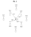
- FIG. 2 illustrates an exemplary inter-node coordinated transmission.
- FIG. 3 is a flowchart illustrating a method for transmitting channel state information from a UE to a BS by a multi-node system.
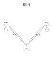
- FIGS. 4 and 5 illustrate a channel matrix and a beam matrix formed between each node and a UE, respectively.
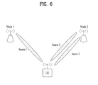
- FIG. 6 illustrates exemplary nodes for supporting different ranks.
- FIG. 7 is a block diagram illustrating a user equipment (UE) and a base station (BS) applicable to embodiments of the present invention.
- UE user equipment
- BS base station
- a user equipment may be a fixed or mobile user equipment (UE), and may be any one of various devices that transmit and receive user data and/or various kinds of control information by communicating with a base station (BS).
- the UE may be referred to as a Terminal Equipment, Mobile Station (MS), Mobile Terminal (MT), User Terminal (UT), Subscriber Station (SS), wireless device, Personal Digital Assistant (PDA), wireless modem, or handheld device.
- a Base Station is a fixed station that generally communicates with a UE or another BS.
- the BS communicates with a UE or another BS to exchange various kinds of data and control information with a UE or another BS.
- the BS may be referred to as an Advanced Base Station (ABS), Node-B (NB), evolved-NodeB (eNB), Base Transceiver System (BTS), Access Point (AP), or Processing Server (PS).
- ABS Advanced Base Station
- NB Node-B
- eNB evolved-NodeB
- BTS Base Transceiver System
- channel status information refers to information capable of representing a quality of a radio channel (or link) established between a UE and a node.
- the channel status information may be a Channel Quality Indicator (CQI), a Rank Index (RI), or a Precoding Matrix Index (PMI).
- CQI Channel Quality Indicator
- RI Rank Index
- PMI Precoding Matrix Index
- CSI channel state information
- the term “stream” means an input path of each information applied to the precoder.
- the term “stream” may also be replaced with a transmission stream, a data stream, a transmission layer, or a layer.
- One transport block (TB) may be encoded into one codeword (CW).
- the transmitter may transmit one or more codewords.
- the transmission apparatus may transmit each codeword configured in the form of one or more streams to the receiver.
- FIG. 1 illustrates an exemplary configuration of a multi-node system, particularly, a distributed multi-node system (DMNS).
- DMNS distributed multi-node system
- a plurality of nodes spaced apart and arranged in a predetermined geographical area are linked to one BS or BS controller through cables or dedicated lines in the DMNS. That is, one controller manages transmission/reception through all the nodes located in the predetermined geographical area.
- each node serves as a group of some antennas of one cell in the DMNS.
- Each node may be given a node ID, or may operate as an antenna in the cell without a node ID in the DMNS.
- this DMNS can be considered as a multi-cell (e.g., macro-cell/femto-cell/pico-cell) system.
- a network constructed by the multiple cells is called a multi-tier network.
- BSs can be used as nodes regardless of their names. That is, BS, NB, eNB, pico-cell eNB (PeNB), home eNB (HeNB), RRH, RRU, relay, repeater, etc. may be used as nodes.
- At least one antenna is installed for one node.
- the antenna may be a physical antenna, an antenna port, a virtual antenna, or an antenna group.
- a node may be called a point.
- the UE may recognize the node through a reference signal (RS).
- RS reference signal
- the UE may use one channel state information RS (CSI-RS) resource as one node.
- CSI-RS resources may be different from each other in terms of at least one of resource configuration, subframe configuration, and 10 sequences.
- FIG. 1 shows a case in which one controller manages transmission/reception through all the nodes located in the predetermined geographical area.
- nodes which perform coordinated communication need not be managed only by one controller.
- Embodiments of the present invention can be applied to a case in which nodes controlled by different BSs or BS controllers perform coordinated communication.
- one or more BSs or BS controllers connected to the plurality of nodes can control the plurality of nodes to simultaneously transmit signals to UE(s) or simultaneously receive signals from the UE(s) through some of the plurality of nodes.
- multi-node systems are distinguished according to the nature and implementation form of each node, the multi-node systems are different from single-node systems (e.g., CAS, conventional MIMO system, conventional relay system, conventional repeater system, etc.) since a plurality of nodes participate in a process of providing a communication service to UEs over a predetermined time-frequency resource. Accordingly, methods for performing coordinated transmission of data using all or some of a plurality of nodes according to embodiments of the present invention can be applied to various types of multi-node systems.
- a node generally refers to an antenna group spaced apart from other nodes by over a predetermined distance
- the following embodiments of the present invention can be applied even when the node means an antenna group regardless of spacing.
- the embodiments of the present invention can be applied on the assumption that the BS controls nodes configured with H-pol antennas and nodes configured with V-pol antennas.
- FIG. 2 illustrates an exemplary multi-node coordinated transmission.
- a plurality of nodes Node 1 to Node 8 are located around a UE, and some Node 1, Node 2, Node 3 and Node 4 of them can be JP candidate nodes which can perform JP for the UE. For instance, when intensities of signals transmitted from Node 1, Node 2, Node 3 and Node 4 are relatively higher, Node 1, Node 2, Node 3 and Node 4 may be JP candidate nodes for the UE.
- a set including Node 1, Node 2, Node 3 and Node 4 be a set A.
- the UE reports channel status information (CSI) on the nodes of the set A to a network. That is, the UE transmits the channel status information (CSI) on the nodes of the set A to a BS linked with the UE.
- CSI channel status information
- FIG. 3 is a flowchart illustrating a method for transmitting channel state information from a UE to a BS by a multi-node system.
- the BS may command the UE belonging to the BS coverage to report channel state information of a plurality of nodes in step S100.
- the plurality of nodes about which CSI report(s) are performed may be decided by the UE, or the BS may inform the UE of the decided nodes.
- the UE may measure a channel state of the plurality of nodes, and may calculate channel state information on the basis of the measured information in step S120.
- the UE may transmit the channel state information to a specific node from among the plurality of nodes, or to each of the plurality of nodes.
- the UE may report the BS of a channel state between the UE and the plurality of nodes in step S140.
- the specific node may be a node in which the UE performs initial network entry or may be a node in which the UE finishes connection to the BS.
- the BS or the network may perform scheduling of the UE on the basis of the channel state information.
- a method for transmitting/receiving node through a plurality of Tx/Rx nodes is referred to as a multi-BS MIMO or a CoMP (coordinated multi-point Tx/Rx).
- the coordinated transmission scheme from among inter-node coordinated communication schemes is largely classified into a Joint Processing (JP) and a Scheduling Coordination.
- JP Joint Processing
- JT Joint Transmission
- DCS Dynamic Cell Selection
- the scheduling coordination scheme may be classified into Coordinated Scheduling (CS) and Coordinated Beamforming (CB).
- CS Coordinated Scheduling
- CB Coordinated Beamforming
- JT from among the JP schemes refers to a transmission scheme in which multiple nodes transmit the same stream to the UE.
- the UE may synthesize signals received from the multiple nodes such that it recovers the above stream.
- reliability of signal transmission can be improved by Transmit Diversity.
- FIGS. 4 and 5 illustrate a channel matrix and a beam matrix formed between each node and a UE, respectively.
- a channel state may be denoted by a channel matrix. It is assumed that a channel matrix indicating a channel state between a Node 1 and a UE is denoted by H1, and a channel matrix indicating a channel state between a Node 2 and a UE is denoted by H2. If Node 1 applies a precoder (w 1 ) to a stream, the stream arrives at the UE through a beam denoted by a matrix H 2 w 2 . If a precoder (w 2 ) of the node 2 is applied to the stream, the stream arrives at the UE through the beam denoted by the matrix H 2 w 2 .
- the Tx signal arrives at the UE through a channel of the matrix H 2 w 2 after application of the precoder (w 1 ).
- the UE may recognize the channel matrix using a reference signal (RS) for measuring a channel from a specific node, and may select the precoder capable of adjusting a phase, an amplitude, etc. of a downlink (DL) signal in such a manner that the adjusted result is beneficial to the UE.
- RS reference signal
- the UE may feed back specific information (i.e., precoding matrix information PMI) indicating a user-desired precoder needed when each node transmits signals to the UE, to the BS.
- specific information i.e., precoding matrix information PMI
- the BS may decide a node which will participate in JT on the basis of the PMIs and/or other channel state information, and/or may decide a precoder to be applied to each node participating in the JT. Therefore, each node participating in JT precodes the stream to be transmitted to the UE to the corresponding precoder, such that it may form a beam beneficial to signal transmission toward the UE. In the meantime, in order to enable signals transmitted from the nodes participating in JT to be constructively overlapped with each other by the UE, a phase difference between beams formed by the nodes must be adjusted.
- the UE may transmit not only a PMI to be used by each node but also a phase adjustment value for adjusting a phase difference between beams to be formed when the corresponding PMIs are applied to the nodes participating in JT to the BS. That is, the UE may calculate a Concatenating PMI (CPMI) for interconnecting PMIs between the nodes such that it may transmit the CPMI to the BS. The UE may feed back not only PMIs and phase adjustment information but also a CQI to the BS.
- CPMI Concatenating PMI
- the feedback information has disadvantages in that it can be used as valid information only when each node participating in JT is maintained for a predetermined time.
- feedback information transmitted for JT has been calculated on the assumption that Rank-1 is transmitted at each node.
- the legacy multi-node system has disadvantages in that it is unable to support a rank higher than Rank-1 to each UE. Therefore, according to a network situation, not only the case in which each node participating in JT is dynamically allocated, but also a method for synthesizing a precoder appropriate for transmission of a higher rank capable of transmitting many more layers (or many more streams) according to the improved link quality is needed
- the embodiments will hereinafter be described with reference to an exemplary case in which the UE selects a PMI of each node from the Rank-1 codebook and transmits the PMI.
- the UE measures a channel state of each of the plurality of nodes, selects a PMI from the Rank-1 codebook for each node, and feeds back the selected PMI to the BS.
- the UE may derive a phase adjustment value (hereinafter referred to as CPMI) between nodes using the selected PMIs, and may feed back the derived phase adjustment value to the BS.
- CPMI phase adjustment value
- the UE may add a PMI and a CPMI so that it may feed back either a correlation value between nodes or specific information indicating the degree of correlation to the BS.
- the BS or the network including the BS may dynamically allocate a JP participation node using PMI, CPMI, correlation information, etc., and may select a precoder appropriate for each allocated node.
- the network may decide a precoder for data to be transmitted from Node 1 to Node 4, a phase adjustment value, and a Modulation and Coding Scheme (MCS) on the basis of the feedback information.
- MCS of data is decided in consideration of CQI.
- CPMI from among the above feedback information may not be fed back, such that the method of the embodiments may also be applied to the system to which CPMI is not fed back.
- the equation including CPMI may also be replaced with another equation including no CPMI without difficulty.
- the UE may assume that a reception (Rx) signal is denoted by the following equation 1.
- H k is a channel from the k-th node
- PMI(k) is a codebook index for the k-th node
- W(m) is a precoding vector corresponding to the codebook index (m).
- 's' is data transmitted from Node 1 to Node 4
- 'v' is noise and interference.
- b(m) is a specific value corresponding to CPMI(m).
- CPMI may be defined as quantized values (for example, ⁇ 0, 1/8, 2/8, ..., 7/8 ⁇ ).
- b(m) is a specific value corresponding to CPMI(m) which is one of the quantized values.
- the UE may decide a correlation value or correlation degree between nodes, and may additionally feed back the decided correlation value or degree to the BS.
- the correlation value or correlation degree between nodes is dependent upon specific information indicating whether signals transmitted through beams formed by the corresponding nodes are constructive or destructive. For example, referring to FIG. 5 , assuming that the UE feeds back the value (w 1 ) for Node 1 and feeds back the value (w 2 ) for Node 2, the UE can expect to receive the following signal (x) from each of Node 1 and Node 2.
- H 1 w 1 is a beam vector between the node 1 and a UE
- H 1 w 2 is a beam vector between the node 2 and the UE. If correlation between the beam vectors is high in level, that is, if correlation between Node 1 and Node 2 is high in level, Node 1 and Node 2 may transmit the same stream as S1 and S2, respectively. In contrast, if correlation between beam vectors is low in level, that is, if correlation between Node 1 and Node 2 is low in level, Node 1 and Node 2 may transmit different streams and may add Spatial Multiplexing (SM) using the different streams.
- SM Spatial Multiplexing
- a correlation value between two nodes may be decided on the basis of correlation between the corresponding beam vectors/matrices H i w i and H j w j .
- low-correlation nodes may transmit different signals to implement system throughput improvement.
- the correlation R between the N nodes may be denoted by the following equation 3.
- Equation 3 'f' is a function of arguments.
- N is the number of nodes.
- an argument of the argument function (f) may be exemplarily calculated using the following equation 4.
- H i ⁇ w i ⁇ H i ⁇ w i / H i ⁇ w i
- H i is a channel from the i-th node, and w i is a precoder for the i-th node. That is, w i is W(PMI(i)). If the i-th node includes a single transmission antenna, w i is a scalar value but not a vector. In another example, H i w i may correspond to a beam having the highest reception power when the beam from among various beams capable of being provided through the i-th node is measured by the UE.
- r ij is a correlation value between one beam provided through the i-th node and the other beam provided through the j-th node.
- r 11 , r 22 , ... , r NN may be autocorrelation values, and need not be fed back to the BS by the UE.
- the autocorrelation value is always set to 1 such that it can be recognized by the BS.
- elements of a lower triangular part are complex-conjugated with elements of a higher triangular part, such that the UE may feed back values of only one part from among the higher part and the lower part to the BS.
- r ij (where, i ⁇ j) may be fed back
- a value approximating to the calculated value r ij from among the predefined values indicating the quantized correlation degrees may also be fed back, instead of the above values. For example, if the correlation degree is high, r ij may be denoted by 1, and if the correlation degree is low, r ij may be denoted by 0.
- the correlation matrix may be denoted by the following equation 5.
- Equation 5 'x' may indicate "don't care”.
- the UE may feed back specific information corresponding to r 12 , r 13 , r 14 , r 23 , r 24 , r 34 , or may feed back information to conjugate values of the specific information to the BS.
- transmission of the quantized values indicating the correlation degree may be defined. For example, '0' may indicate the low correlation degree between the corresponding nodes, and '1' may indicate the high correlation degree between the corresponding nodes.
- the network or the BS having received correlation information indicating either the correlation value or the correlation degree may decide a specific node participating in JT according to the correlation degree between the four nodes, and may configure the precoder in consideration of the correlation degree between the nodes.
- the processor of the network or the processor of the BS may decide correlation between the nodes on the basis of the above-mentioned correlation information. In other words, if the precoder is synthesized at each node according to UE feedback information on the basis of the correlation information, correlation between the beam vectors/matrices formed between each node and the UE can be estimated.
- Equation 5 may also be represented by the correlation degree matrix shown in the following equation 6.
- the UE assumes that Node 1, Node 2, Node 3, and Node 4 participate in JT, the UE assumes that one stream is transmitted at Node 1 and Node 2 and also assumes that another stream is transmitted at Node 3 and Node 4. Therefore, it can be assumed that the UE is going to receive the following signal X in the range from Node 1 to Node 4.
- Equation 7 [e j2 ⁇ b(1) W(PMI(1)) e j2 ⁇ b(1) W(PMI(1)) 0 0] T is a beam vector for s 1 , and [0 0 e j2 ⁇ b(3) W(PMI(1)) e j2 ⁇ b(4) W(PMI(1))] T is a beam vector for for s 2 .
- the reception signal (X) assumed by the UE can be represented by the following equation 8.
- the UE may use only one node (e.g., Node 1) as a reference node for CPMI calculation, such that it may feed back the CPMI to the remaining nodes (Node 2, Node 3, Node 4) other than Node 1.
- Node 1 a reference node for CPMI calculation
- the UE may feed back the CPMI using the correlation between the nodes.
- the UE may expect that the high correlation nodes will transmit the same stream, and may feed back only the CPMI of the remaining nodes other than one node from among the nodes of a group composed of high-correlation nodes as necessary. If there is high correlation between Node 1 and Node 1 and there is high correlation between Node 3 and Node 4, the UE may feed back a CPMI for adjusting a phase of the Node 1 on the basis of the Node 2, and may feed back a CPMI for adjusting a phase of the Node 3 on the basis of the Node 4.
- the UE may feed back an aggregate or set of nodes capable of simultaneously transmitting the same stream to the BS.
- the UE may feed back specific information indicating reception of two streams to the BS.
- the UE may feed back specific information, that indicates that an aggregate ⁇ 1, 2 ⁇ composed of Node 1 and Node 2 can transmit one of two streams and an aggregate ⁇ 3, 4 ⁇ composed of Node 2 and Node 3 can transmit the other one of two stream, to the BS.
- every node uses Rank-1 precoder for convenience of description.
- the number of streams capable of being allocated by each node may be changed according to a Tx antenna configuration of each node.
- the scope or spirit of the present invention may be extended to the case in which nodes use different ranks. That is, the method for calculating correlation between nodes may be extended to another method for calculating correlation in consideration of ranks of respective nodes as necessary. For example, if the UE can receive a plurality of streams from a specific node, the UE may generate the parameter R in the same manner as in the case in which individual beam vectors carrying the plurality of streams are transmitted through different nodes.
- the correlation R is an (M*M)-sized matrix. That is, if M instead of N is used in Equation 3, the following correlation matrix based on consideration of per-node rank can be obtained as represented by the following equation 10.
- Equation 10 'f' is the function of arguments.
- the factor 'f' may be decided using the following equation 11.
- H i ⁇ w i ⁇ H i ⁇ w i 1 / H i ⁇ w i 1 ⁇ H i ⁇ w i R i / H i ⁇ w i R i
- H i is a channel from the i-th node, and 'wi' is a precoder of the 10 th node, and N is the number of nodes.
- H i w i (k) is the k-th column of H i w i
- R i is a rank of the i-th node. If the i-th node includes only one Tx antenna, w i is denoted by a scalar value.
- H i w i (k) may correspond to the k-th beam from among R i beams having the highest Rx power or highest Rx intensity obtained when the UE performs measurement.
- the UE may feed back values of elements contained in a higher or lower triangular part of the correlation matrix R to the BS.
- the number of elements is denoted by a combination for calculating two points from among M points.
- a total number of correlation information to be fed back by the UE is set to 6 (i.e., r 12 , r 13 , r 14 , r 23 , r 24 , r 34 ). Assuming that the UE feeds back each correlation value to the value of 0 or 1, there is a need for the UE to transmit a total of 256 bits as correlation information.
- the correlation degree between streams of the node need not be fed back.
- the number of streams capable of being transmitted to the UE by a specific node is higher than 1, this means that the specific node forms mutually independent transmission (Tx) channels (i.e., low correlation beams) such that different streams can be transmitted to the UE. Therefore, considering the above-mentioned situation, the amount of feedback information of the UE is denoted by the following equation 12.
- the UE can support Rank-2 at Node 1 and can also support Rank-1 at Node 3, the UE has to feed back only two (i.e., r 13 , r 23 ) from among feedback elements (i.e., r 12 , r 13 , r 23 ) of the (3*3)-sized correlation matrix.
- the network assumes that the feedback element (r 12 ) corresponding to the correlation between the same nodes is set to zero (0). If the case in which the correlation value is high is set to 1 and the other case in which the correlation value is low is set to 0, a value decided by Equation 12 may correspond to the amount of feedback information.
- each node supports a rank higher than Rank-1.
- the embodiment capable of supporting a rank higher than Rank-1 when the UE feeds back a PMI for each node, it may select a PMI from a codebook corresponding to a rank of the corresponding node.
- FIG. 6 shows exemplary nodes for supporting different ranks.
- the network forms a beam capable of transmitting only one stream (Beam 1) at the node 1 and forms beams (Beam 2 and Beam 3) for transmitting two streams at the node 2, it is impossible to recognize which stream must be transmitted at each beam. That is, it is impossible to recognize which precoder will be combined at each node.
- the network transmits Stream S1 and Stream S2 to the UE through Node 2, it is impossible for the network to recognize which one of streams S 1 and S2 will be transmitted through Beam 1 of the node 1 for higher efficiency. Therefore, according to one embodiment, if the UE feeds back a PMI for a node supporting a lower rank, an index (or an index of a layer) of a stream to be transmitted at the corresponding node is further fed back to the BS.
- the stream index of each node may be decided on the basis of the correlation between the corresponding node and the stream of a different node.
- the UE selects a PMI for the node 1 in the Rank-2 codebook and feeds back the selected PMI, and selects a PMI for each of Nodes 2 to 4 in the Rank-1 codebook and feeds back the selected PMI.
- the UE may further feed back specific information indicating which one of streams will be more preferably transmitted at each of Node 2, Node 3, and Node 4, each of which is decided as Rank-1.
- the UE may further transmit a phase adjustment value for compensating a phase difference between streams. For example, the UE may transmit a CPMI for each of Node 2, Node 3, and Node 3 to the BS on the basis of Node 4 capable of transmitting a plurality of streams.
- the UE must transmit a first stream S1 at the node 2, must transmit a second stream S2 at the node 3, and must transmit the second stream S2 at the node 4.
- the UE determines that all the nodes 1 to 4 participate in JT by the network, it can be assumed that the UE receives the following signal denoted by Equation 13.
- W m is a precoder contained in the Rank-m codebook.
- the UE will receive the following signal.
- the present invention includes the embodiment in which the UE performs grouping of each node according to a rank, and PMI and CPMI for each group are fed back to the BS.
- the UE selects a PMI(1) and a PMI(2) for Node 1 and Node 2 from among the Rank-2 codebook, feeds back the selected PMI(1) and PMI(2), and feeds back a CPMI of Node 2.
- the UE selects PMI(3) and PMI(4) for Node 3 and Node 4 in the Rank-1 codebook, feeds back the selected PMI(3) and PMI(4), and feeds back a CPMI of Node 4.
- the UE may calculate a phase adjustment value between nodes supporting the same rank, and may report the calculated phase adjustment value to the BS.
- the UE assumes that Node 1 and Node 2 simultaneously perform JT so as to feed back a CQI of Node 1 and Node 2, and assumes that Node 3 and Node 4 simultaneously perform JT, such that it may feed back a CQI of Node 3 and Node 4.
- the network may perform JT using Node 1 and Node 2.
- the JT may support up to Rank-2.
- the network performs JT using Node 3 and Node 4
- the JT may support up to Rank-1.
- the network (or BS) according to the embodiment enables a plurality of nodes capable of supporting different ranks not to simultaneously participate in JT.
- PMI may not be fed back to a point including only one Tx antenna. If there is only one Tx antenna, it is impossible to form a beam in the corresponding node, the network does not require a PMI for the corresponding node. Therefore, the UE may feed back only a CPMI for correcting a phase difference between the corresponding node and another node at the corresponding node.
- the UE feeds back a CPMI per stream or per layer to the BS at a node supporting Rank-2 or higher, because a phase difference to be corrected per stream may be differently established.
- the UE according to the embodiment may transmit not only PMI, CPMI, and/or correlation information but also a CQI to the BS. If the number of candidate nodes capable of participating in JT is set to N and the node to be participated in JT is dynamically allocated by the network, the number of combinations of nodes participating in JT is denoted by the following equation 15.
- Equation 15 can be extended to the number of combinations of streams capable of being transmitted at nodes participating in JT.
- the amount of CQI feedback overhead increases in proportion to the increasing number of nodes and/or streams. Therefore, the present invention provides a CQI feedback method capable of reducing CQI feedback overhead in the multi-node system.
- the UE assumes that the network will exclude candidate nodes will be eliminated in ascending numerical order of signal strength and may feed back a CQI to the network. For example, assuming that JT candidate nodes are Node 1, Node 2, Node 3 and Node 4 and the signal strength is denoted by Node 1 > Node 2 > Node 3 > Node 4, the UE may assume the following JP node combination.
- the UE may feed back only a CQI of each of the four JP node combinations to the BS.
- signal transmission by one node cannot be considered to be JT, such that the UE may feed back a CQI to JP node combinations (1) to (3).
- the UE may feed back a CQI for each node so as to inform a BS of the signal strength of each node.
- the BS can recognize UL signal strength of each node. Generally, if UL strength is high, this means that the DL signal strength is also high.
- the BS may implicitly estimate the DL signal strength order on the basis of the UL signal strength for each node. Therefore, per-node CQI transmission by the UE is optional according to the embodiment.
- the CQI feedback method can reduce CQI overhead. For example, since a total of 15 JP node combinations may be possible for four JP candidate nodes, the UE has to feed back 15 CQIs to the BS in consideration of a CQI feedback of a single node. However, according to the embodiment, although a CQI for only one node must be fed back in association with four JP candidate nodes, it is necessary for the UE to feed back only four CQIs to the BS.
- the above-mentioned CQI feedback method according to the embodiment may be simultaneously or separately carried out along with the embodiments of the above-mentioned precoding information transmission.
- the network or BS may allow the UE to select a node that will attempt to perform JT on the basis of precoding information and/or CQI transmitted from the UE to the BS, may select or allocated a stream for each node, and may select a UE to which the stream will be transmitted.
- the UE may measure a channel formed between the UE and the corresponding node using a reference signal (RS) transmitted from the corresponding node.
- RS reference signal
- CRS Cell-specific RS
- CSI-RS channel state information RS
- the RS may be called a pilot, preamble, or mid-amble, a signal can be used as the RS of the present invention irrespective of the term thereof if the signal is used by the UE for channel estimation/measurement.
- time-frequency resource sets which transmit the reference signals can be predefined in a predetermined resource region defined by a plurality of time-frequency resources. Accordingly, a predetermined number of neighboring nodes in the multi-node system can be configured to transmit their reference signals on different resource sets.
- the BS can notify the UE of a time-frequency resource set through which the node set for CQI report transmits its reference signal.
- the UE may measure a channel state using signals received through the time-frequency resource set notified by the BS, and may transmit the calculated CQI to the BS.
- the BS can request the UE to report a channel state for a plurality of nodes by notifying the UE of the node set comprised of nodes requiring channel state report, such that the BS may request the UE to report CSI of the node set.
- the BS can request the UE to report a channel state of the node set by informing the UE of a time-frequency resource set from which the UE should detect/receive a signal to be used for measurement of channel status information (CSI).
- CSI channel status information
- the UE may receive reference signals (RSs) transmitted from the plurality of time-frequency resource sets, such that it may calculate the above-mentioned channel state information (for example, PMI, CQI, phase adjustment value, correlation value, rank information, stream information, etc.) for the corresponding time-frequency resource set.
- RSs reference signals
- FIG. 7 is a block diagram illustrating a user equipment (UE) and a base station (BS) applicable to embodiments of the present invention.
- UE user equipment
- BS base station
- the UE serves as a transmitter on the uplink and as a receiver on the downlink.
- the BS may serve as a receiver on the uplink and as a transmitter on the downlink.
- the UE and the BS include antennas 500a and 500b for receiving information, data, signals, and/or messages, transmitters 100a and 100b for transmitting messages by controlling the antennas 500a and 500b, receivers 300a and 300b for receiving messages by controlling the antennas 500a and 500b, and memories 200a and 200b for storing information associated with communication in the wireless communication system.
- the UE and the BS further include processors 400a and 400b, respectively, which are adapted to perform the present invention by controlling the components of the UE and the BS, such as the transmitters 100a and 100b, the receivers 300a and 300b, and the memories 200a and 200b.
- the transmitter 100a, the memory 200a, the receiver 300a, and the processor 400a in the UE may be configured as independent components on separate chips or their separate chips may be incorporated into a single chip.
- the transmitter 100b, the memory 200b, the receiver 300b, and the processor 400b in the BS may be configured as independent components on separate chips or their separate chips may be incorporated into a single chip.
- the transmitter and the receiver may be configured as a single transceiver in the UE or the BS.
- the memories 200a and 200b may store programs required for signal processing and controlling of the processors 400a and 400b and temporarily store input and output information.
- the memories 200a and 200b may be used as buffers.
- Each of the memories 200a and 200b may be implemented into a flash memory-type storage medium, a hard disc-type storage medium, a multimedia card micro-type storage medium, a card-type memory (e.g. a Secure Digital (SD) or eXtreme Digital (XD) memory), a Random Access Memory (RAM), a Read-Only Memory (ROM), an Electrically Erasable Programmable Read-Only Memory (EEPROM), a Programmable Read-Only Memory (PROM), a magnetic memory, a magnetic disc, or an optical disk.
- SD Secure Digital
- XD eXtreme Digital
- RAM Random Access Memory
- ROM Read-Only Memory
- EEPROM Electrically Erasable Programmable Read-Only Memory
- PROM Programmable Read-Only Memory
- the antennas 500a and 500b transmit signals generated from the transmitters 100a and 100b to the outside, or transfer radio frequency (RF) signals received from the outside to the receivers 300a and 300b.
- the antennas 500a and 500b may be referred as antenna ports.
- Each antenna port may correspond to one physical antenna or may be configured into a combination of more than one physical antenna element. In either case, the signal transmitted from each antenna port is not designed to be further deconstructed by the UE receiver 300a.
- the transmitted reference signal corresponding to a given antenna port defines the antenna port from the viewpoint of the UE, and enables the UE to derive channel estimation for that antenna port, regardless of whether it represents a single radio channel from one physical antenna or a composite channel from a plurality of physical antenna elements together comprising the antenna port.
- an antenna is defined such that a channel transmitting a symbol on the antenna may be derived from the channel transmitting another symbol on the same antenna.
- a transceiver supporting a MIMO function of transmitting and receiving data using a plurality of antennas may be connected to two or more antennas. All or some of antennas included in the BS can operate as nodes according to the embodiments of the present invention.
- the embodiments of the present invention can be applied to nodes spaced apart by over a predetermined distance among the nodes of the BS. Further, the embodiments of the present invention can be applied to nodes which are not spaced apart from among the nodes of the BS if the nodes can be used for coordinated transmission of data to the UE with different coverages. In addition, the embodiments of the present invention can be applied to nodes used for coordinated transmission together with nodes included in other BSs.
- the processors 400a and 400b generally provide overall control to the modules of the UE and the BS. Especially, the processors 400a and 400b may carry out a control function for performing the present invention, a Medium Access Control (MAC) frame variable control function based on service characteristics and a propagation environment, a power saving mode function for controlling idle-mode operations, a handover function, and an authentication and encryption function.
- the processors 400a and 400b may also be referred to as controllers, microcontrollers, microprocessors, microcomputers, etc.
- the processors 400a and 400b may be configured in hardware, firmware, software, or their combination.
- the processors 400a and 400b may be provided with one or more Application Specific Integrated Circuits (ASICs), Digital Signal Processors (DSPs), Digital Signal Processing Devices (DSPDs), Programmable Logic Devices (PLDs), and/or Field Programmable Gate Arrays (FPGAs), for implementing the present invention.
- ASICs Application Specific Integrated Circuits
- DSPs Digital Signal Processors
- DSPDs Digital Signal Processing Devices
- PLDs Programmable Logic Devices
- FPGAs Field Programmable Gate Arrays
- firmware or software may be configured to include a module, a procedure, a function, etc. for performing functions or operations of the present invention. This firmware or software may be provided in the processors 400a and 400b, or may be stored in the memories 200a and 200b and driven by the processors 400a and 400b.
- the processors 400and 400b the transmitters 100a and 100b are scheduled from a scheduler connected to the processors and code and modulate signals and/or data to be transmitted to the exterior.
- the coded and modulated signals and/or data are transmitted to the antennas 500a and 500b.
- the transmitters 100a and 100b convert a data stream to be transmitted into K streams through demultiplexing, channel coding, and modulation.
- the k streams are transmitted to the Tx antennas 500a and 500b through the transmission processor contained in the transmitter.
- the signal processing procedure of the receivers 300a and 300b is the reverse of the signal processing procedure of the transmitters. Specifically, the receivers 300a and 300b perform decoding and demodulation of wireless signals received from the outside through the antennas 500a and 500b and deliver the resulting signals to the corresponding processors 400a and 400b.
- Each of the antennas 500a and 500b connected to the receivers 300a and 300b may include N r reception antennas. Each of the signals received through the reception antennas is reconstructed into a baseband signal and is then reconstructed into a data stream, which was originally intended to be transmitted by the transmitters 100a and 100b, through multiplexing and MIMO demodulation.
- the transmitters 100a and 100b and the receivers 300a and 300b of the UE and the BS may be configured in different manners depending on the procedures of processing transmitted signals and received signals. Let modules including the transmitters 100a and 100b, the receivers 300a and 300b, and the antennas 500a and 500b be called radio frequency (RF) units.
- RF radio frequency
- the transmitter 100b and the receiver 300b of the BS may be installed per node or per BS. That is, each node of the embodiments may be a unit that includes an antenna, the transmitter 100b, and the receiver 300b, or may be a unit that does not include the transmitter 100b and the receiver 300b.
- the UE processor 400a may control the UE operations.
- the UE processor 400a may control the UE receiver 300a to receive DL signals (e.g., a reference signal (RS), control information, stream, etc.) from one or more nodes.
- the UE processor 400a may measure a channel state of the corresponding node using the channel measurement RS from each node.
- the UE processor 400a may decide/calculate/generate precoding information (for example, PMI, CPMI and/or correlation information) and/or CQI using the channel state measurement result.
- the UE processor 400a may control the transmitter 100a to transmit the precoding information and/or CQI according to one embodiment.
- the UE receiver 300a may receive signals from one or more nodes under the control of the UE processor 400a. If two or more nodes participate in JT, the UE processor 400a overlaps signals received from the two or more nodes so that it can recover stream(s) transmitted for the UE.
- the BS processor 400a may control the operations carried out by either the BS or the network.
- the BS processor 400b may control the operations of one or more nodes connected to the corresponding BS.
- the BS processor 400b may allow the UE entering the BS network to decide a specific node to be participated in JP on the basis of feedback information transmitted according to embodiments.
- the BS processor 400b may control two or more nodes in such a manner that the two or more nodes connected to a dedicated line of the BS processor 400b perform JT processing for the UE located in the BS coverage.
- the BS processor 400b may cooperate with a processor of a different BS so that it may perform JT for the UE through its own node and a node controlled by the processor of the different BS.
- the BS processor 400b may decide whether the node contained in the corresponding BS will transmit the same stream as in another node contained in the BS or other BSs or will transmit a stream different from those of the another node. If nodes contained in different BSs perform JT, the BS processor 400b may control a node connected thereto for transmission of a specific stream, and the processor of another BS may control a node connected thereto for transmission of the specific stream.
- the BS processor 400b may decide a precoder to be applied to the node of the BS processor 400b on the basis of feedback information.
- the BS may decide a stream (or layer) to be used by each node, and decide the number of streams to be transmitted by each node. If nodes communicating with the UE belong to the plurality of BSs but not one BS, the BS processors 400b cooperate with each other so as to decide a precoder, a stream, a rank, etc. at a node connected to each BS processor.
- the BS processor 400a may decide MCS to be applied to DL transmission by one or more nodes on the basis of CQI information received from the UE according to one embodiment.
- the BS processor 400b may precode the stream(s) allocated to the corresponding node into the selected precoder, and may control the corresponding node to transmit the precoded stream(s).
- the corresponding node may transmit the precoded stream(s) to the UE through the Tx antenna.
- nodes participating in JT may be dynamically allocated according to a network situation.
- the multi-node system can support a rank higher than Rank-1.
- the amount of overhead for channel state report in the multi-node system may be reduced. Therefore, according to the embodiments, the data processing throughput of the multi-node system can be improved.
- the embodiments of the present invention can be applied to a UE, a BS (eNB), or other devices in a wireless communication system.
Landscapes
- Engineering & Computer Science (AREA)
- Computer Networks & Wireless Communication (AREA)
- Signal Processing (AREA)
- Mobile Radio Communication Systems (AREA)
Applications Claiming Priority (3)
| Application Number | Priority Date | Filing Date | Title |
|---|---|---|---|
| US201161436193P | 2011-01-26 | 2011-01-26 | |
| US201161475208P | 2011-04-13 | 2011-04-13 | |
| PCT/KR2012/000614 WO2012102558A2 (fr) | 2011-01-26 | 2012-01-26 | Procédé de transmission d'informations d'état de canal et équipement utilisateur, procédé de réception d'informations d'état de canal et station de base |
Publications (3)
| Publication Number | Publication Date |
|---|---|
| EP2670059A2 true EP2670059A2 (fr) | 2013-12-04 |
| EP2670059A4 EP2670059A4 (fr) | 2014-11-19 |
| EP2670059B1 EP2670059B1 (fr) | 2021-03-03 |
Family
ID=46581292
Family Applications (1)
| Application Number | Title | Priority Date | Filing Date |
|---|---|---|---|
| EP12739741.2A Active EP2670059B1 (fr) | 2011-01-26 | 2012-01-26 | Procédé de transmission d'informations d'état de canal et équipement utilisateur, procédé de réception d'informations d'état de canal et station de base |
Country Status (3)
| Country | Link |
|---|---|
| US (1) | US9215704B2 (fr) |
| EP (1) | EP2670059B1 (fr) |
| WO (1) | WO2012102558A2 (fr) |
Cited By (1)
| Publication number | Priority date | Publication date | Assignee | Title |
|---|---|---|---|---|
| WO2024054138A1 (fr) * | 2022-09-07 | 2024-03-14 | Telefonaktiebolaget Lm Ericsson (Publ) | Sélection de mode de transmission pour desservir un équipement utilisateur dans un réseau d-mimo |
Families Citing this family (9)
| Publication number | Priority date | Publication date | Assignee | Title |
|---|---|---|---|---|
| EP2635087A1 (fr) * | 2012-02-28 | 2013-09-04 | Alcatel Lucent | Appareil, procédé et programme informatique pour contrôler des points de transmission dans un système de communication mobile |
| WO2014176813A1 (fr) * | 2013-04-28 | 2014-11-06 | 华为技术有限公司 | Procédé de retour d'information sur un indicateur de matrice de précodage, extrémité réceptrice et extrémité émettrice |
| US9867059B2 (en) * | 2013-09-06 | 2018-01-09 | Telefonaktiebolaget Lm Ericsson (Publ) | Distributed node operation in heterogeneous networks |
| US10277286B2 (en) | 2013-12-23 | 2019-04-30 | Telefonaktiebolaget Lm Ericsson (Publ) | Determining position of a wireless device using remote radio head devices with multiple antenna devices |
| JP6573610B2 (ja) * | 2014-07-25 | 2019-09-11 | 株式会社Nttドコモ | ユーザ装置および基地局 |
| US10129889B1 (en) * | 2015-09-01 | 2018-11-13 | Sprint Spectrum L.P. | Selecting primary and secondary component carriers for carrier aggregation based on carrier receive power at a UE, transmit power, frequency, and other carrier attributes |
| GB2558217B (en) * | 2016-12-22 | 2020-08-19 | Samsung Electronics Co Ltd | Using feedback from user equipment to determine mode of joint transmission |
| US10298355B2 (en) * | 2017-02-28 | 2019-05-21 | Corning Incorporated | Supporting cooperative transmission in massive multiple-input multiple-output (MIMO) systems |
| US12273750B2 (en) | 2021-02-17 | 2025-04-08 | Samsung Electronics Co., Ltd. | Method and apparatus for measuring and reporting communication parameters |
Family Cites Families (16)
| Publication number | Priority date | Publication date | Assignee | Title |
|---|---|---|---|---|
| RU2145152C1 (ru) * | 1998-10-08 | 2000-01-27 | Гармонов Александр Васильевич | Способ ортогональной разнесенной передачи-приема сигнала в сотовой системе радиосвязи с кодовым разделением каналов |
| EP1775875A1 (fr) * | 2004-08-04 | 2007-04-18 | Matsushita Electric Industrial Co., Ltd. | Dispositif de communication radio, systeme de communication radio, et procede de communication radio |
| FI20075282A0 (fi) * | 2007-04-23 | 2007-04-23 | Nokia Corp | Taajuusvirheen estimointialgoritmi |
| JP5024548B2 (ja) * | 2008-03-13 | 2012-09-12 | 日本電気株式会社 | 制御信号復調装置、制御信号復調方法、無線通信装置およびプログラム |
| KR100970891B1 (ko) * | 2008-05-07 | 2010-07-20 | 재단법인서울대학교산학협력재단 | 무선 통신 시스템에서 공간 분할 다중화 기법을 위한 채널정보 생성 장치 및 그 방법과 이를 이용한 데이터 전송장치 및 그 방법 |
| JP5195925B2 (ja) * | 2009-01-15 | 2013-05-15 | 富士通株式会社 | 送信装置、通信システム、通信方法 |
| KR101579749B1 (ko) | 2009-03-25 | 2015-12-24 | 삼성전자주식회사 | 다중 입출력 무선통신 시스템에서 하향 링크를 위한 공동 빔 성형 방법 및 그를 수행하기 위한 송수신 장치 |
| WO2010131354A1 (fr) * | 2009-05-15 | 2010-11-18 | 富士通株式会社 | Procédé permettant une commutation d'un système de modulation, station de transmission et station de réception |
| CN102006124B (zh) * | 2009-08-28 | 2014-05-07 | 华为技术有限公司 | 频谱预测方法、装置和系统 |
| CN102056220B (zh) * | 2009-10-28 | 2014-02-19 | 华为技术有限公司 | 实现信道测量的方法及装置 |
| TWI404360B (zh) * | 2009-11-25 | 2013-08-01 | Inst Information Industry | 用於一多輸入多輸出正交分頻多工系統之通訊裝置及其方法 |
| JP5446857B2 (ja) * | 2009-12-28 | 2014-03-19 | 富士通株式会社 | 中継装置、無線中継方法 |
| AU2011227860B2 (en) * | 2010-03-17 | 2015-02-12 | Qualcomm Incorporated | Method and apparatus for providing channel state information-reference signal (CSI-RS) configuration information in a wireless communication system supporting multiple antennas |
| EP2566068A4 (fr) * | 2010-04-27 | 2015-08-26 | Fujitsu Ltd | Dispositif pour relais sans fil et procédé pour relais sans fil |
| US8521199B2 (en) * | 2010-06-15 | 2013-08-27 | Futurewei Technologies, Inc. | System and method for transparent coordinated beam-forming |
| EP2583382A1 (fr) | 2010-06-18 | 2013-04-24 | Nec Corporation | Techniques de précodage pour une transmission multipoint coordonnée de liaison descendante dans un système de communication radio |
-
2012
- 2012-01-26 WO PCT/KR2012/000614 patent/WO2012102558A2/fr not_active Ceased
- 2012-01-26 EP EP12739741.2A patent/EP2670059B1/fr active Active
- 2012-01-26 US US13/981,872 patent/US9215704B2/en not_active Expired - Fee Related
Cited By (1)
| Publication number | Priority date | Publication date | Assignee | Title |
|---|---|---|---|---|
| WO2024054138A1 (fr) * | 2022-09-07 | 2024-03-14 | Telefonaktiebolaget Lm Ericsson (Publ) | Sélection de mode de transmission pour desservir un équipement utilisateur dans un réseau d-mimo |
Also Published As
| Publication number | Publication date |
|---|---|
| EP2670059A4 (fr) | 2014-11-19 |
| EP2670059B1 (fr) | 2021-03-03 |
| WO2012102558A3 (fr) | 2012-09-20 |
| US9215704B2 (en) | 2015-12-15 |
| US20130308590A1 (en) | 2013-11-21 |
| WO2012102558A2 (fr) | 2012-08-02 |
Similar Documents
| Publication | Publication Date | Title |
|---|---|---|
| EP2670059B1 (fr) | Procédé de transmission d'informations d'état de canal et équipement utilisateur, procédé de réception d'informations d'état de canal et station de base | |
| US8755451B2 (en) | Method for transmitting precoded signal in collaborative multiple-input multiple-output communication system | |
| CN102598525B (zh) | 在使用CoMP传输的无线通信系统中终端传输反馈信息的方法和装置 | |
| US8989115B2 (en) | Method for transmitting precoding matrix information and user device, and method for transmitting data to plurality of user devices and base station | |
| EP3228021B1 (fr) | Procédé et appareil de signalisation de liaison descendante pour retour d'informations de csi-rs et de csi partiellement précodées | |
| US9882690B2 (en) | Method and apparatus for transmitting information about a channel in a wireless communication system | |
| US20220094399A1 (en) | Low overhead channel state information (csi) feedback for multi-transmission point (trp) transmission | |
| CN105075322B (zh) | 在天线阵列中获取信道状态信息的方法和装置 | |
| US8665817B2 (en) | Method and apparatus for mode switching between a multi-cell coordinated communication mode and a single-cell MIMO communication mode | |
| TW202312688A (zh) | 用於無線通訊的方法及使用者設備 | |
| US9357419B2 (en) | Method for reporting channel state information in wireless communication system and apparatus for same | |
| US9167465B2 (en) | Method for transceiving channel state information and transceiving device | |
| US9467273B2 (en) | Apparatus and method for reducing inter-cell interference in multiple input multiple output system | |
| WO2009084905A2 (fr) | Procédé de réduction du brouillage intercellulaire | |
| US9923736B2 (en) | Method for performing channel estimation, and apparatus therefor | |
| US20120328035A1 (en) | Data transmission method and apparatus in mimo communication system | |
| US20130279455A1 (en) | Method for reporting channel state information in a wireless communication system, and apparatus therefor | |
| EP2912875A1 (fr) | Procédé de renvoi d'informations d'état de canal dans un système de communication sans fil et appareil s'y rapportant | |
| US8699610B2 (en) | Feedback scheme for multi-cell interference mitigation consideration legacy mobile users | |
| WO2017116119A1 (fr) | Procédé pour rapporter un indicateur de signal de référence à une station de base par un terminal dans un système de communication sans fil et appareil associé | |
| US20140023033A1 (en) | Method and apparatus for transceiving channel status information and transceiver | |
| KR20090077185A (ko) | 협력적 다중 입출력 통신 시스템에서 코드북 기반의빔포밍을 수행하는 방법 | |
| US20140092811A1 (en) | Method for transmitting channel status information and user equipment, and method for receiving channel status information and base station | |
| Peng et al. | A novel CSI feedback method for dynamic SU/MU MIMO adaptation |
Legal Events
| Date | Code | Title | Description |
|---|---|---|---|
| PUAI | Public reference made under article 153(3) epc to a published international application that has entered the european phase |
Free format text: ORIGINAL CODE: 0009012 |
|
| 17P | Request for examination filed |
Effective date: 20130821 |
|
| AK | Designated contracting states |
Kind code of ref document: A2 Designated state(s): AL AT BE BG CH CY CZ DE DK EE ES FI FR GB GR HR HU IE IS IT LI LT LU LV MC MK MT NL NO PL PT RO RS SE SI SK SM TR |
|
| DAX | Request for extension of the european patent (deleted) | ||
| A4 | Supplementary search report drawn up and despatched |
Effective date: 20141021 |
|
| RIC1 | Information provided on ipc code assigned before grant |
Ipc: H04B 7/06 20060101ALI20141015BHEP Ipc: H04B 7/02 20060101ALI20141015BHEP Ipc: H04W 72/04 20090101ALI20141015BHEP Ipc: H04B 7/04 20060101AFI20141015BHEP |
|
| STAA | Information on the status of an ep patent application or granted ep patent |
Free format text: STATUS: EXAMINATION IS IN PROGRESS |
|
| 17Q | First examination report despatched |
Effective date: 20180514 |
|
| GRAP | Despatch of communication of intention to grant a patent |
Free format text: ORIGINAL CODE: EPIDOSNIGR1 |
|
| STAA | Information on the status of an ep patent application or granted ep patent |
Free format text: STATUS: GRANT OF PATENT IS INTENDED |
|
| RIC1 | Information provided on ipc code assigned before grant |
Ipc: H04B 7/04 20170101AFI20200630BHEP Ipc: H04W 72/04 20090101ALI20200630BHEP Ipc: H04B 7/06 20060101ALI20200630BHEP Ipc: H04B 7/02 20180101ALI20200630BHEP Ipc: H04B 7/024 20170101ALI20200630BHEP |
|
| INTG | Intention to grant announced |
Effective date: 20200804 |
|
| GRAJ | Information related to disapproval of communication of intention to grant by the applicant or resumption of examination proceedings by the epo deleted |
Free format text: ORIGINAL CODE: EPIDOSDIGR1 |
|
| STAA | Information on the status of an ep patent application or granted ep patent |
Free format text: STATUS: EXAMINATION IS IN PROGRESS |
|
| GRAS | Grant fee paid |
Free format text: ORIGINAL CODE: EPIDOSNIGR3 |
|
| STAA | Information on the status of an ep patent application or granted ep patent |
Free format text: STATUS: GRANT OF PATENT IS INTENDED |
|
| GRAP | Despatch of communication of intention to grant a patent |
Free format text: ORIGINAL CODE: EPIDOSNIGR1 |
|
| INTC | Intention to grant announced (deleted) | ||
| INTG | Intention to grant announced |
Effective date: 20201208 |
|
| GRAA | (expected) grant |
Free format text: ORIGINAL CODE: 0009210 |
|
| STAA | Information on the status of an ep patent application or granted ep patent |
Free format text: STATUS: THE PATENT HAS BEEN GRANTED |
|
| AK | Designated contracting states |
Kind code of ref document: B1 Designated state(s): AL AT BE BG CH CY CZ DE DK EE ES FI FR GB GR HR HU IE IS IT LI LT LU LV MC MK MT NL NO PL PT RO RS SE SI SK SM TR |
|
| REG | Reference to a national code |
Ref country code: GB Ref legal event code: FG4D |
|
| REG | Reference to a national code |
Ref country code: AT Ref legal event code: REF Ref document number: 1368368 Country of ref document: AT Kind code of ref document: T Effective date: 20210315 Ref country code: CH Ref legal event code: EP |
|
| REG | Reference to a national code |
Ref country code: DE Ref legal event code: R096 Ref document number: 602012074615 Country of ref document: DE |
|
| REG | Reference to a national code |
Ref country code: IE Ref legal event code: FG4D |
|
| REG | Reference to a national code |
Ref country code: LT Ref legal event code: MG9D |
|
| PG25 | Lapsed in a contracting state [announced via postgrant information from national office to epo] |
Ref country code: HR Free format text: LAPSE BECAUSE OF FAILURE TO SUBMIT A TRANSLATION OF THE DESCRIPTION OR TO PAY THE FEE WITHIN THE PRESCRIBED TIME-LIMIT Effective date: 20210303 Ref country code: GR Free format text: LAPSE BECAUSE OF FAILURE TO SUBMIT A TRANSLATION OF THE DESCRIPTION OR TO PAY THE FEE WITHIN THE PRESCRIBED TIME-LIMIT Effective date: 20210604 Ref country code: FI Free format text: LAPSE BECAUSE OF FAILURE TO SUBMIT A TRANSLATION OF THE DESCRIPTION OR TO PAY THE FEE WITHIN THE PRESCRIBED TIME-LIMIT Effective date: 20210303 Ref country code: LT Free format text: LAPSE BECAUSE OF FAILURE TO SUBMIT A TRANSLATION OF THE DESCRIPTION OR TO PAY THE FEE WITHIN THE PRESCRIBED TIME-LIMIT Effective date: 20210303 Ref country code: BG Free format text: LAPSE BECAUSE OF FAILURE TO SUBMIT A TRANSLATION OF THE DESCRIPTION OR TO PAY THE FEE WITHIN THE PRESCRIBED TIME-LIMIT Effective date: 20210603 Ref country code: NO Free format text: LAPSE BECAUSE OF FAILURE TO SUBMIT A TRANSLATION OF THE DESCRIPTION OR TO PAY THE FEE WITHIN THE PRESCRIBED TIME-LIMIT Effective date: 20210603 |
|
| REG | Reference to a national code |
Ref country code: NL Ref legal event code: MP Effective date: 20210303 |
|
| REG | Reference to a national code |
Ref country code: AT Ref legal event code: MK05 Ref document number: 1368368 Country of ref document: AT Kind code of ref document: T Effective date: 20210303 |
|
| PG25 | Lapsed in a contracting state [announced via postgrant information from national office to epo] |
Ref country code: SE Free format text: LAPSE BECAUSE OF FAILURE TO SUBMIT A TRANSLATION OF THE DESCRIPTION OR TO PAY THE FEE WITHIN THE PRESCRIBED TIME-LIMIT Effective date: 20210303 Ref country code: RS Free format text: LAPSE BECAUSE OF FAILURE TO SUBMIT A TRANSLATION OF THE DESCRIPTION OR TO PAY THE FEE WITHIN THE PRESCRIBED TIME-LIMIT Effective date: 20210303 Ref country code: PL Free format text: LAPSE BECAUSE OF FAILURE TO SUBMIT A TRANSLATION OF THE DESCRIPTION OR TO PAY THE FEE WITHIN THE PRESCRIBED TIME-LIMIT Effective date: 20210303 Ref country code: LV Free format text: LAPSE BECAUSE OF FAILURE TO SUBMIT A TRANSLATION OF THE DESCRIPTION OR TO PAY THE FEE WITHIN THE PRESCRIBED TIME-LIMIT Effective date: 20210303 |
|
| PG25 | Lapsed in a contracting state [announced via postgrant information from national office to epo] |
Ref country code: NL Free format text: LAPSE BECAUSE OF FAILURE TO SUBMIT A TRANSLATION OF THE DESCRIPTION OR TO PAY THE FEE WITHIN THE PRESCRIBED TIME-LIMIT Effective date: 20210303 |
|
| PG25 | Lapsed in a contracting state [announced via postgrant information from national office to epo] |
Ref country code: CZ Free format text: LAPSE BECAUSE OF FAILURE TO SUBMIT A TRANSLATION OF THE DESCRIPTION OR TO PAY THE FEE WITHIN THE PRESCRIBED TIME-LIMIT Effective date: 20210303 Ref country code: EE Free format text: LAPSE BECAUSE OF FAILURE TO SUBMIT A TRANSLATION OF THE DESCRIPTION OR TO PAY THE FEE WITHIN THE PRESCRIBED TIME-LIMIT Effective date: 20210303 Ref country code: SM Free format text: LAPSE BECAUSE OF FAILURE TO SUBMIT A TRANSLATION OF THE DESCRIPTION OR TO PAY THE FEE WITHIN THE PRESCRIBED TIME-LIMIT Effective date: 20210303 Ref country code: AT Free format text: LAPSE BECAUSE OF FAILURE TO SUBMIT A TRANSLATION OF THE DESCRIPTION OR TO PAY THE FEE WITHIN THE PRESCRIBED TIME-LIMIT Effective date: 20210303 |
|
| PG25 | Lapsed in a contracting state [announced via postgrant information from national office to epo] |
Ref country code: SK Free format text: LAPSE BECAUSE OF FAILURE TO SUBMIT A TRANSLATION OF THE DESCRIPTION OR TO PAY THE FEE WITHIN THE PRESCRIBED TIME-LIMIT Effective date: 20210303 Ref country code: PT Free format text: LAPSE BECAUSE OF FAILURE TO SUBMIT A TRANSLATION OF THE DESCRIPTION OR TO PAY THE FEE WITHIN THE PRESCRIBED TIME-LIMIT Effective date: 20210705 Ref country code: ES Free format text: LAPSE BECAUSE OF FAILURE TO SUBMIT A TRANSLATION OF THE DESCRIPTION OR TO PAY THE FEE WITHIN THE PRESCRIBED TIME-LIMIT Effective date: 20210303 Ref country code: RO Free format text: LAPSE BECAUSE OF FAILURE TO SUBMIT A TRANSLATION OF THE DESCRIPTION OR TO PAY THE FEE WITHIN THE PRESCRIBED TIME-LIMIT Effective date: 20210303 Ref country code: IS Free format text: LAPSE BECAUSE OF FAILURE TO SUBMIT A TRANSLATION OF THE DESCRIPTION OR TO PAY THE FEE WITHIN THE PRESCRIBED TIME-LIMIT Effective date: 20210703 |
|
| REG | Reference to a national code |
Ref country code: DE Ref legal event code: R097 Ref document number: 602012074615 Country of ref document: DE |
|
| PLBE | No opposition filed within time limit |
Free format text: ORIGINAL CODE: 0009261 |
|
| STAA | Information on the status of an ep patent application or granted ep patent |
Free format text: STATUS: NO OPPOSITION FILED WITHIN TIME LIMIT |
|
| PG25 | Lapsed in a contracting state [announced via postgrant information from national office to epo] |
Ref country code: DK Free format text: LAPSE BECAUSE OF FAILURE TO SUBMIT A TRANSLATION OF THE DESCRIPTION OR TO PAY THE FEE WITHIN THE PRESCRIBED TIME-LIMIT Effective date: 20210303 Ref country code: AL Free format text: LAPSE BECAUSE OF FAILURE TO SUBMIT A TRANSLATION OF THE DESCRIPTION OR TO PAY THE FEE WITHIN THE PRESCRIBED TIME-LIMIT Effective date: 20210303 |
|
| 26N | No opposition filed |
Effective date: 20211206 |
|
| PG25 | Lapsed in a contracting state [announced via postgrant information from national office to epo] |
Ref country code: SI Free format text: LAPSE BECAUSE OF FAILURE TO SUBMIT A TRANSLATION OF THE DESCRIPTION OR TO PAY THE FEE WITHIN THE PRESCRIBED TIME-LIMIT Effective date: 20210303 |
|
| PG25 | Lapsed in a contracting state [announced via postgrant information from national office to epo] |
Ref country code: IT Free format text: LAPSE BECAUSE OF FAILURE TO SUBMIT A TRANSLATION OF THE DESCRIPTION OR TO PAY THE FEE WITHIN THE PRESCRIBED TIME-LIMIT Effective date: 20210303 |
|
| PG25 | Lapsed in a contracting state [announced via postgrant information from national office to epo] |
Ref country code: IS Free format text: LAPSE BECAUSE OF FAILURE TO SUBMIT A TRANSLATION OF THE DESCRIPTION OR TO PAY THE FEE WITHIN THE PRESCRIBED TIME-LIMIT Effective date: 20210703 |
|
| PG25 | Lapsed in a contracting state [announced via postgrant information from national office to epo] |
Ref country code: MC Free format text: LAPSE BECAUSE OF FAILURE TO SUBMIT A TRANSLATION OF THE DESCRIPTION OR TO PAY THE FEE WITHIN THE PRESCRIBED TIME-LIMIT Effective date: 20210303 |
|
| REG | Reference to a national code |
Ref country code: CH Ref legal event code: PL |
|
| GBPC | Gb: european patent ceased through non-payment of renewal fee |
Effective date: 20220126 |
|
| REG | Reference to a national code |
Ref country code: BE Ref legal event code: MM Effective date: 20220131 |
|
| PG25 | Lapsed in a contracting state [announced via postgrant information from national office to epo] |
Ref country code: LU Free format text: LAPSE BECAUSE OF NON-PAYMENT OF DUE FEES Effective date: 20220126 Ref country code: GB Free format text: LAPSE BECAUSE OF NON-PAYMENT OF DUE FEES Effective date: 20220126 |
|
| PG25 | Lapsed in a contracting state [announced via postgrant information from national office to epo] |
Ref country code: FR Free format text: LAPSE BECAUSE OF NON-PAYMENT OF DUE FEES Effective date: 20220131 Ref country code: BE Free format text: LAPSE BECAUSE OF NON-PAYMENT OF DUE FEES Effective date: 20220131 |
|
| PG25 | Lapsed in a contracting state [announced via postgrant information from national office to epo] |
Ref country code: LI Free format text: LAPSE BECAUSE OF NON-PAYMENT OF DUE FEES Effective date: 20220131 Ref country code: CH Free format text: LAPSE BECAUSE OF NON-PAYMENT OF DUE FEES Effective date: 20220131 |
|
| PG25 | Lapsed in a contracting state [announced via postgrant information from national office to epo] |
Ref country code: IE Free format text: LAPSE BECAUSE OF NON-PAYMENT OF DUE FEES Effective date: 20220126 |
|
| PG25 | Lapsed in a contracting state [announced via postgrant information from national office to epo] |
Ref country code: HU Free format text: LAPSE BECAUSE OF FAILURE TO SUBMIT A TRANSLATION OF THE DESCRIPTION OR TO PAY THE FEE WITHIN THE PRESCRIBED TIME-LIMIT; INVALID AB INITIO Effective date: 20120126 |
|
| PG25 | Lapsed in a contracting state [announced via postgrant information from national office to epo] |
Ref country code: MK Free format text: LAPSE BECAUSE OF FAILURE TO SUBMIT A TRANSLATION OF THE DESCRIPTION OR TO PAY THE FEE WITHIN THE PRESCRIBED TIME-LIMIT Effective date: 20210303 Ref country code: CY Free format text: LAPSE BECAUSE OF FAILURE TO SUBMIT A TRANSLATION OF THE DESCRIPTION OR TO PAY THE FEE WITHIN THE PRESCRIBED TIME-LIMIT Effective date: 20210303 |
|
| PG25 | Lapsed in a contracting state [announced via postgrant information from national office to epo] |
Ref country code: TR Free format text: LAPSE BECAUSE OF FAILURE TO SUBMIT A TRANSLATION OF THE DESCRIPTION OR TO PAY THE FEE WITHIN THE PRESCRIBED TIME-LIMIT Effective date: 20210303 |
|
| PG25 | Lapsed in a contracting state [announced via postgrant information from national office to epo] |
Ref country code: MT Free format text: LAPSE BECAUSE OF FAILURE TO SUBMIT A TRANSLATION OF THE DESCRIPTION OR TO PAY THE FEE WITHIN THE PRESCRIBED TIME-LIMIT Effective date: 20210303 |
|
| PGFP | Annual fee paid to national office [announced via postgrant information from national office to epo] |
Ref country code: DE Payment date: 20251208 Year of fee payment: 15 |