EP2670141A1 - Dispositif de codage vidéo, dispositif de décodage vidéo, procédé de codage vidéo, procédé de décodage vidéo et programme - Google Patents
Dispositif de codage vidéo, dispositif de décodage vidéo, procédé de codage vidéo, procédé de décodage vidéo et programme Download PDFInfo
- Publication number
- EP2670141A1 EP2670141A1 EP11852257.2A EP11852257A EP2670141A1 EP 2670141 A1 EP2670141 A1 EP 2670141A1 EP 11852257 A EP11852257 A EP 11852257A EP 2670141 A1 EP2670141 A1 EP 2670141A1
- Authority
- EP
- European Patent Office
- Prior art keywords
- intra prediction
- edge information
- transform
- image
- block
- Prior art date
- Legal status (The legal status is an assumption and is not a legal conclusion. Google has not performed a legal analysis and makes no representation as to the accuracy of the status listed.)
- Withdrawn
Links
- 238000000034 method Methods 0.000 title claims description 48
- 238000013139 quantization Methods 0.000 claims abstract description 94
- 238000003708 edge detection Methods 0.000 claims abstract description 44
- 238000005192 partition Methods 0.000 description 39
- 238000010586 diagram Methods 0.000 description 28
- 238000004364 calculation method Methods 0.000 description 5
- 238000012545 processing Methods 0.000 description 5
- 230000006870 function Effects 0.000 description 4
- 241000023320 Luma <angiosperm> Species 0.000 description 3
- 230000010365 information processing Effects 0.000 description 3
- OSWPMRLSEDHDFF-UHFFFAOYSA-N methyl salicylate Chemical compound COC(=O)C1=CC=CC=C1O OSWPMRLSEDHDFF-UHFFFAOYSA-N 0.000 description 3
- 238000001514 detection method Methods 0.000 description 2
- 230000000694 effects Effects 0.000 description 2
- 238000013213 extrapolation Methods 0.000 description 2
- NRNCYVBFPDDJNE-UHFFFAOYSA-N pemoline Chemical compound O1C(N)=NC(=O)C1C1=CC=CC=C1 NRNCYVBFPDDJNE-UHFFFAOYSA-N 0.000 description 2
- 230000002093 peripheral effect Effects 0.000 description 2
- 238000012360 testing method Methods 0.000 description 2
- 101150114515 CTBS gene Proteins 0.000 description 1
- 238000004590 computer program Methods 0.000 description 1
- 238000007796 conventional method Methods 0.000 description 1
- 238000009795 derivation Methods 0.000 description 1
- 238000013519 translation Methods 0.000 description 1
Images







Classifications
-
- H—ELECTRICITY
- H04—ELECTRIC COMMUNICATION TECHNIQUE
- H04N—PICTORIAL COMMUNICATION, e.g. TELEVISION
- H04N19/00—Methods or arrangements for coding, decoding, compressing or decompressing digital video signals
- H04N19/10—Methods or arrangements for coding, decoding, compressing or decompressing digital video signals using adaptive coding
- H04N19/169—Methods or arrangements for coding, decoding, compressing or decompressing digital video signals using adaptive coding characterised by the coding unit, i.e. the structural portion or semantic portion of the video signal being the object or the subject of the adaptive coding
- H04N19/17—Methods or arrangements for coding, decoding, compressing or decompressing digital video signals using adaptive coding characterised by the coding unit, i.e. the structural portion or semantic portion of the video signal being the object or the subject of the adaptive coding the unit being an image region, e.g. an object
- H04N19/176—Methods or arrangements for coding, decoding, compressing or decompressing digital video signals using adaptive coding characterised by the coding unit, i.e. the structural portion or semantic portion of the video signal being the object or the subject of the adaptive coding the unit being an image region, e.g. an object the region being a block, e.g. a macroblock
-
- H—ELECTRICITY
- H04—ELECTRIC COMMUNICATION TECHNIQUE
- H04N—PICTORIAL COMMUNICATION, e.g. TELEVISION
- H04N19/00—Methods or arrangements for coding, decoding, compressing or decompressing digital video signals
- H04N19/10—Methods or arrangements for coding, decoding, compressing or decompressing digital video signals using adaptive coding
- H04N19/102—Methods or arrangements for coding, decoding, compressing or decompressing digital video signals using adaptive coding characterised by the element, parameter or selection affected or controlled by the adaptive coding
- H04N19/103—Selection of coding mode or of prediction mode
- H04N19/11—Selection of coding mode or of prediction mode among a plurality of spatial predictive coding modes
-
- H—ELECTRICITY
- H04—ELECTRIC COMMUNICATION TECHNIQUE
- H04N—PICTORIAL COMMUNICATION, e.g. TELEVISION
- H04N19/00—Methods or arrangements for coding, decoding, compressing or decompressing digital video signals
- H04N19/10—Methods or arrangements for coding, decoding, compressing or decompressing digital video signals using adaptive coding
- H04N19/134—Methods or arrangements for coding, decoding, compressing or decompressing digital video signals using adaptive coding characterised by the element, parameter or criterion affecting or controlling the adaptive coding
- H04N19/136—Incoming video signal characteristics or properties
- H04N19/14—Coding unit complexity, e.g. amount of activity or edge presence estimation
-
- H—ELECTRICITY
- H04—ELECTRIC COMMUNICATION TECHNIQUE
- H04N—PICTORIAL COMMUNICATION, e.g. TELEVISION
- H04N19/00—Methods or arrangements for coding, decoding, compressing or decompressing digital video signals
- H04N19/42—Methods or arrangements for coding, decoding, compressing or decompressing digital video signals characterised by implementation details or hardware specially adapted for video compression or decompression, e.g. dedicated software implementation
- H04N19/423—Methods or arrangements for coding, decoding, compressing or decompressing digital video signals characterised by implementation details or hardware specially adapted for video compression or decompression, e.g. dedicated software implementation characterised by memory arrangements
-
- H—ELECTRICITY
- H04—ELECTRIC COMMUNICATION TECHNIQUE
- H04N—PICTORIAL COMMUNICATION, e.g. TELEVISION
- H04N19/00—Methods or arrangements for coding, decoding, compressing or decompressing digital video signals
- H04N19/50—Methods or arrangements for coding, decoding, compressing or decompressing digital video signals using predictive coding
- H04N19/593—Methods or arrangements for coding, decoding, compressing or decompressing digital video signals using predictive coding involving spatial prediction techniques
-
- H—ELECTRICITY
- H04—ELECTRIC COMMUNICATION TECHNIQUE
- H04N—PICTORIAL COMMUNICATION, e.g. TELEVISION
- H04N19/00—Methods or arrangements for coding, decoding, compressing or decompressing digital video signals
- H04N19/60—Methods or arrangements for coding, decoding, compressing or decompressing digital video signals using transform coding
- H04N19/61—Methods or arrangements for coding, decoding, compressing or decompressing digital video signals using transform coding in combination with predictive coding
Definitions
- the present invention relates to a video encoding device to which a video encoding technique using edge information is applied, and a video decoding device.
- a video encoding device executes, on a digitized video signal, an encoding process that conforms to a predetermined video coding scheme to generate coded data, i.e. a bitstream.
- AVC Advanced Video Coding
- NPL Non Patent Literature 1
- Joint Model scheme a video encoding device that conforms to the AVC scheme is called a typical video encoding device.
- the typical video encoding device includes a transform/quantization unit 101, an entropy encoding unit 102, an inverse transform/inverse quantization unit 103, an intra prediction unit 104, an encoding control unit 110, and a switch 121.
- the typical video encoding device divides each frame into blocks of 16 ⁇ 16 pixel size called macro blocks (MBs), and further divides each MB into blocks of 4 ⁇ 4 pixel size to set the 4 ⁇ 4 block as the minimum unit of encoding.
- MBs macro blocks
- FIG. 19 is an explanatory diagram showing an example of block division in the case where the frame has a spatial resolution of QCIF (Quarter Common Intermediate Format). The following describes the operation of each unit while focusing only on pixel values of luminance for simplicity's sake.
- QCIF Quadrater Common Intermediate Format
- a prediction signal supplied from the intra prediction unit 104 through the switch 121 is subtracted from an input image of each MB of input video.
- the input video from which the prediction signal is subtracted is called a prediction error below.
- the intra prediction unit 104 generates an intra prediction signal using a reconstructed image having the same display time as a current frame.
- the MB encoded using the intra prediction signal is called an intra MB below.
- Intra_4x4 prediction process for luma samples 8.3.2 Intra_8x8 prediction process for luma samples
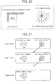
- 8.3.3 Intra_16x16 prediction process for luma samples in NPL 1 three types of intra prediction modes (Intra_4 ⁇ 4, Intra_8 ⁇ 8, and Intra_16 ⁇ 16) are available.
- Intra_4 ⁇ 4 is described with reference to FIG. 20 .
- Each circle (o) in (a) of FIG. 20 represents a reference pixel used for intra prediction, i.e. a pixel of the reconstructed picture having the same display time as the current picture.
- intra prediction of Intra_4 ⁇ 4 reconstructed peripheral pixels are directly set as reference pixels, each of which is used for padding (extrapolation) in any one of nine directions shown in (b) of FIG. 20 to form a prediction signal.
- the direction of extrapolation is called the intra prediction direction below.
- the encoding control unit 110 compares the nine types of intra prediction signals with each MB signal of input video, selects an intra prediction direction that minimizes the energy of the prediction error, and causes the intra prediction unit to supply the intra prediction signal of the selected intra direction to the switch 121.
- the selected intra prediction mode and information associated with the intra prediction direction are supplied to the entropy encoding unit 102.
- the transform/quantization unit 101 frequency-transforms the prediction error based on the discrete cosine transform of 4 ⁇ 4 or 8 ⁇ 8.
- the transform/quantization unit 101 further quantizes, with a predetermined quantization step width Qs, a prediction error image (frequency transform coefficient) obtained by the frequency-transform.
- the quantized frequency transform coefficient is called a transform quantization value below.
- the entropy encoding unit 102 entropy-encodes the intra prediction mode and the intra prediction direction supplied from the encoding control unit 110, and the transform quantization value supplied from the transform/quantization unit 101.
- the inverse transform/inverse quantization unit 103 inverse-quantizes the transform quantization value with the quantization step width Qs. Based on the discrete cosine transform of 4 ⁇ 4 or 8 ⁇ 8, the inverse transform/inverse quantization unit 103 further performs inverse frequency transform of the frequency transform coefficient obtained by the inverse quantization. The prediction signal is added to the reconstructed prediction error image obtained by the inverse frequency transform, and set as a reconstructed image.
- the typical video encoding device Based on the operation described above, the typical video encoding device generates a bitstream.
- CTBs Coding Tree Block
- SCTB Smallest Coding Tree Block
- a CTB block is called a Coding Unit (CU) below.
- the LCTB is called the LCU (Largest Coding Unit)
- the SCTB is called the SCU (Smallest Coding Unit).
- PU Prediction Unit
- PU Prediction Unit
- FIG. 22 the concept of Prediction Unit (PU) is introduced as a unit of prediction for each CTB as shown in FIG. 22 .
- much more types of intra prediction directions are supported.
- 33 types of intra prediction directions (a total of 33 types, with 16 types indicated by the solid lines on the right side of the lower right diagonal indicated by the broken line, and 16 types indicated by the solid lines on the left side of the broken line) other than DC are supported in 8 ⁇ 8 intra PU partitions (34 types including DC in total).
- 17 types are supported in 4 ⁇ 4 intra PU partitions
- 34 types are supported in 16 ⁇ 16 and 32 ⁇ 32 intra PU partitions
- five types are supported in 64x64 intra PU partitions.
- PTL 1 to PTL 4 As conventional techniques for reducing a computation of the encoding control unit 110, there are techniques described in PTL 1 to PTL 4. In PTL 1 to PTL 4, high-speed determination methods for intra prediction mode to determine an intra prediction direction based on edge information on an intra block to be encoded are described.
- PTL 1 and PTL 2 disclose exemplary embodiments using an edge direction histogram and gradient activities as edge information, respectively.
- PTL 3 discloses an exemplary embodiment using, as edge information, frequency transform coefficient information on an intra block to be encoded.
- PTL 4 discloses a high-speed determination method for intra prediction mode using an estimated sum of prediction blocks determined by mathematic functions of the sum of pixels of an intra block to be encoded and peripheral boundary pixels.
- the computation of the encoding control unit 110 can be reduced, but the problem that the coded bit amount of the intra prediction direction increases is not solved.
- PTL 5 and NPL 2 disclose exemplary embodiments for using edge information on blocks adjacent to an intra block to be encoded to determine an intra prediction direction used to encode the intra block to be encoded. According to these techniques, the coded bit amount of the intra prediction direction can be reduced, but the problem that the computation of the encoding control unit 110 increases is not solved.
- the TMuC scheme cannot solve both the problem that the computation of the encoding control unit 110 increases and the problem that the coded bit amount of the intra prediction direction increases properly. This is because the unit of encoding is variable in the TMuC scheme.
- the TMuC scheme since a lot of coding noise is generated in a reconstructed image at a block boundary position, it is not preferred to use edge information at the block boundary position in order to determine an intra prediction direction used to encode the intra block to be encoded.
- block boundary positions associated with intra prediction and frequency transform are not determined until the split block shape of CU is determined, memory allocation for storing edge information on non-block boundary positions is not determined.
- a video encoding device includes: intra prediction means for performing intra prediction on an image; frequency transform/quantization means for frequency-transforming and quantizing a prediction error based on the intra prediction performed by the intra prediction means; entropy encoding means for entropy-encoding a transform quantization value generated by the frequency transform/quantization means; edge detection means for detecting edge information on an image block of the minimum frequency-transform block size of the image; and edge information storage means for storing the edge information detected by the edge detection means.
- a video decoding device includes: entropy decoding means for entropy-decoding a transform quantization value; inverse quantization/inverse frequency transform means for inverse-quantizing the transform quantization value and performing inverse frequency transform thereof; intra prediction means for performing intra prediction on an image; edge detection means for detecting edge information on an image block of the minimum frequency-transform block size of the image; and intra prediction direction selecting means for selecting an intra prediction direction used to decode a block to be decoded, based on the edge information detected by the edge detection means.
- a video encoding method includes: performing intra prediction on an image; frequency-transforming and quantizing a prediction error based on the intra prediction to generate a transform quantization value; entropy-encoding the transform quantization value; detecting edge information on an image block of the minimum frequency-transform block size of the image; and storing the detected edge information in edge information storage means.
- a video decoding method includes: entropy-decoding a transform quantization value; inverse-quantizing the transform quantization value and performing inverse frequency transform thereof; performing intra prediction on an image; detecting edge information on an image block of the minimum frequency-transform block size of the image; and selecting an intra prediction direction used to decode a block to be decoded, based on the detected edge information.
- a video encoding program causes a computer to execute: a process of performing intra prediction on an image; a process of frequency-transforming and quantizing a prediction error based on the intra prediction to generate a transform quantization value; a process of entropy-encoding the transform quantization value; a process of detecting edge information on an image block of the minimum frequency-transform block size of the image; and a process of storing the detected edge information in edge information storage means.
- a video decoding program causes a computer to execute: a process of entropy-decoding a transform quantization value; a process of inverse-quantizing the transform quantization value and performing inverse frequency transform thereof; a process of performing intra prediction on an image; a process of detecting edge information on an image block of the minimum frequency-transform block size of the image; and a process of selecting an intra prediction direction used to decode a block to be decoded, based on the detected edge information.
- both the reduction in a computation of an encoding control unit and the reduction in the coded bit amount of an intra prediction direction can be satisfied properly in a video encoding scheme in which the unit of encoding is variable.
- FIG. 1 is a block diagram showing a video encoding device in Exemplary Embodiment 1.
- the video encoding device in this exemplary embodiment includes an edge detection unit 105, an edge information buffer 106, and an intra prediction direction selector 107 in addition to the transform/quantization unit 101, the entropy encoding unit 102, the inverse transform/inverse quantization unit 103, the intra prediction unit 104, the encoding control unit 110, and the switch 121.
- the following describes the operation of the video encoding device in the exemplary embodiment by taking, as an example, a case where the LCU size is 64 ⁇ 64, the SCU size is 8 ⁇ 8, and the minimum frequency-transform block size is 4 ⁇ 4 (see FIG. 2 ).
- the edge detection unit 105 divides the input image of the LCU into blocks of the minimum frequency-transform block size (4x4 block size), detects edge information on a position corresponding to the inside of each 4 ⁇ 4 block (2 ⁇ 2 pixel), and supplies the result to the edge information buffer 106.
- FIG. 3 illustrates the positions of the edge information relative to the input image of the 64x64 LCU.
- the LCU size is 64 ⁇ 64
- the edge information is the normal vector of a gradient vector to be described below.
- the angle of the normal vector is quantized by a predetermined angle, e.g., 5.45 degrees (180 degrees/33 directions).
- the edge information buffer 106 stores edge information SrcNormal[x,y] on the input image supplied from the edge detection unit 105, and edge information RecNormal[x,y] on a reconstructed image supplied from the edge detection unit 105 to be described later. Since the number of pieces of edge information corresponding to the predetermined position (x,y) is one, the edge information buffer 106 overwrites the edge information SrcNormal[x,y] on the input image with the edge information RecNormal [x,y] on the reconstructed image.
- the encoding control unit 110 uses the edge information SrcNormal[x,y] on the input image of the LCU to be encoded to determine a split block shape of the LCU.
- the encoding control unit 110 divides the LCU equally in quarters (see FIG. 4 ), and calculates a mode (mode value) of edge information belonging to each CU.
- FIG. 4 illustrates the positions of the edge information used when a 2N ⁇ 2N LCU (64 ⁇ 64 in the exemplary embodiment) is divided into four N ⁇ N (32 ⁇ 32) CUs.
- the encoding control unit 110 determines not to divide the LCU.
- the encoding control unit 110 determines to divide the LCU into four CUs.
- the encoding control unit 110 applies similar processing to hierarchically divided CUs to determine the split block shape of the LCU.
- Input images of PU partitions of the CU corresponding to the split block shape determined by the encoding control unit 110 are supplied to the encoding control unit 110.
- the encoding control unit 110 compares the input images of the PU partitions with an intra prediction signal, corresponding to at most seven types of intra prediction directions to be described later, supplied from the intra prediction direction selector 107 to determine an intra prediction direction that minimizes the energy of the prediction error.
- the encoding control unit 110 causes the intra prediction unit 104 to supply the intra prediction signal of the determined intra direction to the switch 121.
- the selected split block shape (split_coding_unit_flag, mode_table_idx, and intra_split_flag) of the LCU, and information (prev_intra_luma_pred_flag and rem_intra_luma_pred_mode) associated with the intra prediction direction are supplied to the entropy encoding unit 102.
- split_coding_unit_flag, mode_table_idx, intra_split_flag, prev_intra_luma_pred_flag, and rem intra_luma_pred_mode are syntaxes in the CU layer and the PU layer described in 4.1.9 Coding unit syntax and 4.1.10 Prediction unit syntax of NPL 2.
- the intra prediction direction selector 107 selects four categories of intra prediction directions.
- a first category is one intra prediction direction smaller in IntraPredMode[ puPartIdx ] between the intra prediction direction of a PU partition A leftwardly adjacent to a PU partition (Current PU partition) to be predicted and an upwardly adjacent PU partition B shown in FIG. 5 .
- IntraPredMode[ puPartIdx ] is the number of an intra prediction mode corresponding to the intra prediction direction described in Table 5-1 Specification of IntraPredMode[ puPartIdx ] and associated names of NPL 2.
- a second category is one intra prediction direction corresponding to the mode of edge information RecNormal [x,y] adjacent to the PU partition. Since RecNormal [x,y] is information obtained based on a reconstructed image (specifically, each pixel value of the reconstructed image) Rec [x,y] positioned inside of each block of the minimum frequency-transform block size, i.e., since RecNormal[x,y] is information not based on a reconstructed image Rec [x,y] positioned on the block boundary, the influence of a block distortion is avoided.
- a third category is one intra prediction direction corresponding to the mode of edge information SrcNormal[x,y] on the input image of the PU partition.
- a fourth category contains a total of four intra prediction directions, i.e. DC, horizontal, vertical, and lower right diagonal, more common in image characteristics.
- the total of intra prediction direction types in all the categories selected by the intra prediction direction selector 107 are seven types at most.
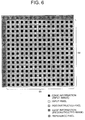
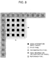
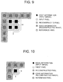
- edge information used to determine the intra prediction directions in the third category and the fourth category for each of the PU partition sizes 64 ⁇ 64, 32 ⁇ 32, 16 ⁇ 16, 8 ⁇ 8, and 4 ⁇ 4 are shown in FIG. 6 to FIG. 10 , respectively. Note that edge information on positions where there is no reconstructed image is not used in determining the fourth intra prediction directions.
- the intra prediction unit 104 generates an intra prediction signal of the intra prediction direction determined by the encoding control unit 110.
- the prediction signal supplied from the intra prediction unit 104 through the switch 121 is subtracted from the input image of the PU partition.
- the transform/quantization unit 101 frequency-transforms the prediction error based on either one of the discrete cosine transforms of 4 ⁇ 4, 8 ⁇ 8, 16 ⁇ 16, 32 ⁇ 32, and 64 ⁇ 64 less than or equal to the size of the CU to be encoded.
- the transform/quantization unit 101 further quantizes, with a predetermined quantization step width Qs, a prediction error image (frequency transform coefficient) obtained by the frequency transform to generate a transform quantization value.
- the entropy encoding unit 102 entropy-encodes the intra prediction mode and the intra prediction direction supplied from the encoding control unit 110, and the transform quantization value supplied from the transform/quantization unit 101.
- Information on the block size of discrete cosine transform (split_transform_unit_flag described in 4.1.11 Transform unit syntax of NPL 2) is also entropy-encoded.
- the inverse transform/inverse quantization unit 103 inverse-quantizes the transform quantization value with the quantization step width Qs.
- the inverse transform/inverse quantization unit 103 further performs inverse frequency transform of the frequency transform coefficient obtained by the inverse quantization based on either one of the discrete cosine transforms of 4 ⁇ 4, 8 ⁇ 8, 16 ⁇ 16, 32 ⁇ 32, and 64 ⁇ 64 less than or equal to the size of the CU to be encoded.
- the prediction signal is added to the reconstructed prediction error image obtained by the inverse frequency transform to form a reconstructed image.
- the edge detection unit 105 divides a reconstructed image Rec[x,y] corresponding to input video of the PU partition into blocks of the minimum frequency-transform block size (4 ⁇ 4 block size), detects edge information RecNormal [x,y] corresponding to the inside of each of the 4 ⁇ 4 blocks, and supplies the result to the edge information buffer 106.
- the edge information buffer 106 is caused to overwrite the edge information SrcNormal[x,y] corresponding to the input video of the PU partition with the edge information RecNormal[x,y] on the reconstructed image.
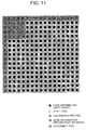
- FIG. 11 shows an exemplary case where edge information SrcNormal [x,y] is overwritten with edge information RecNormal [x,y] after 16 ⁇ 16 intra PU partitions located in the top-left part of the LCU is reconstructed.
- FIG. 11 is an explanatory diagram showing edge information stored in the edge information buffer 106 after the 16x16 intra PU partitions are reconstructed. In FIG. 11 , the top-left part enclosed by the heavy line is the overwritten part.
- the video encoding device in the exemplary embodiment applies the above-described operation to the remaining input images of the LCU.
- the video encoding device in the exemplary embodiment Based on the operation described above, the video encoding device in the exemplary embodiment generates a bitstream.
- the structure of a video encoding device in Exemplary Embodiment 2 is the same as the structure of the video encoding device in Exemplary Embodiment 1 shown in FIG. 1 , but the video encoding device in this exemplary embodiment causes the encoding control unit 110 not to transmit the rem_intra_luma_pred_mode syntax in the information (prev_intra_luma_pred_flag and rem_intra_luma_pred_mode) associated with the intra prediction direction under specific conditions to be described below.
- the specific conditions are such conditions that the intra prediction direction of the first category in Exemplary Embodiment 1 is DC and prev_intra luma_pred_flag is transmitted as 1 (i.e. conditions under which rem_intra_luma_pred_mode is not transmitted).
- prev_intra luma_pred_flag is transmitted as 1 (i.e. conditions under which rem_intra_luma_pred_mode is not transmitted).
- the intra prediction direction predicted based on the intra prediction directions of the blocks leftwardly and upwardly adjacent to the PU partition is DC, and that the predicted intra prediction direction of the DC is the intra prediction direction of the PU partition.
- the encoding control unit 110 in the exemplary embodiment performs intra prediction by the intra prediction direction of the second category in Exemplary Embodiment 1 on a PU partition that falls under the above specific conditions to encode the PU partition.
- the video encoding device in the exemplary embodiment can reduce the coded bit amount of the intra prediction mode in the bitstream while fulfilling the requirements for avoiding the influence of a block distortion and determining the memory allocation for storing edge information.
- the encoding control unit 110 selects, based on edge information on each image block of the minimum frequency-transform block size, the number of intra prediction directions for each of which the prediction error is calculated to determine an intra prediction direction used to encode the intra block to be encoded.
- the position (inside position) of the image block of the minimum frequency-transform block size is a non-block boundary position and a determined position independent of the split block shape of the CU.
- the edge information on the image block of the minimum frequency-transform block size is free of the influence of any block distortion and the memory allocation of the edge information is determined.
- the video encoding device can reduce a computation of the encoding control unit 110 by simplifying the memory allocation of edge information and the calculation of the edge information while reducing the coded bit amount of the intra prediction direction using edge information on the non-block boundary position.
- the video encoding device makes use of the fact that the memory allocation is determined to store edge information on each image block of the minimum frequency-transform block size in the edge information buffer 106. Since the stored edge information can be reused, the number of edge information detections can be reduced. In the case of the video encoding devices in the aforementioned exemplary embodiments, the number of detections of edge information per minimum frequency-transform block size is two (for the input image and the reconstructed image).
- the video encoding device calculates the energy of the prediction error only for the selected intra prediction direction
- the computation of the encoding control unit 110 that calculates the energy of the prediction error can be reduced.
- the calculation of the energy of the prediction error only has to be made for up to seven types of intra prediction directions without the need to calculate the energy of the prediction error for 34 types of intra prediction directions.
- the video encoding device uses edge information to determine the split block shape of the largest coding unit to be encoded, the computation of the encoding control unit 110 that calculates the energy of the prediction error can be reduced.
- the energy of the prediction error only has to be calculated for one split block shape pattern without the need to calculate the energy of the prediction error for a total of four split block shape patterns of 64 ⁇ 64, 32 ⁇ 32, 16 ⁇ 16, and 8 ⁇ 8.
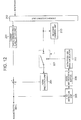
- FIG. 12 is a block diagram showing a video decoding device in Exemplary Embodiment 3.
- the video decoding device in this exemplary embodiment is a video decoding device for decoding a bitstream from the video encoding device in Exemplary Embodiment 2.
- the video decoding device in this exemplary embodiment includes an entropy decoding unit 202, an inverse transform/inverse quantization unit 203, an intra prediction unit 204, a decoding control unit 210, a switch 221, an edge detection unit 205, an edge information buffer 206, and an intra prediction direction selector 207.
- the entropy decoding unit 202 entropy-decodes the bitstream, and outputs the split block shape (split_coding_unit_flag, mode_table_idx and intra_split_flag) of an LCU to be decoded, information (prev_intra_luma_pred_flag and rem_intra_luma_pred_mode) associated with the intra prediction direction, the block size (split_transform_unit_flag) of discrete cosine transform, and the transform quantization value.
- split_coding_unit_flag the split block shape of an LCU to be decoded
- information prev_intra_luma_pred_flag and rem_intra_luma_pred_mode
- the block size split_transform_unit_flag
- the decoding control unit 210 monitors information associated with the intra prediction direction of a PU partition of a CU to be decoded to control the switch 221.
- the intra prediction direction of the first category mentioned above is DC and prev_intra_luma_pred_flag is 1 (when the decoding control unit 210 unambiguously understands that the predicted intra prediction direction of the DC is the intra prediction direction of the PU partition)
- the intra prediction direction determined by the intra prediction direction selector 207 is supplied to the intra prediction unit 204. Otherwise, the intra prediction direction determined by prev_intra_luma_pred_flag and rem intra_luma_pred_mode is supplied to the intra prediction unit 204.
- the intra prediction direction selector 207 selects and supplies, to the switch 221, the intra prediction direction of the second category described above.
- the intra prediction unit 204 uses the reconstructed image to generate an intra prediction signal for the PU partition of the CU to be decoded.
- the inverse transform/inverse quantization unit 203 inverse-quantizes the transform quantization value supplied from the entropy decoding unit 202. Based on the discrete cosine transform of the block size determined by the entropy-decoding, the inverse transform/inverse quantization unit 203 further performs inverse frequency transform to return the result to the original spatial domain.
- the intra prediction signal is added to a reconstructed prediction error returned to the original spatial domain to obtain a reconstructed image of the PU partition of the CU to be decoded.
- the edge detection unit 205 divides the reconstructed image Rec [x,y] of the PU partition of the CU to be decoded into blocks of the minimum frequency-transform block size (4 ⁇ 4 block size), detects edge information RecNormal [x,y] on a position corresponding to the inside of each of the 4 ⁇ 4 blocks, and supplies the result to the edge information buffer 206.
- the operation of the edge detection unit 205 is the same as the operation of the edge detection unit 105 in Exemplary Embodiment 1.
- the intra prediction direction selector 207 is the same as the intra prediction direction selector 107 in Exemplary Embodiment 1.
- the edge information buffer 206 stores the edge information RecNormal [x,y] on the reconstructed image supplied from the edge detection unit 205.
- the video decoding device in the exemplary embodiment applies the above-described operation to the remaining image areas of the LCU.
- the video decoding device in the exemplary embodiment decompresses the bitstream.
- the video decoding device determines an intra prediction direction used to encode an intra block to be encoded, based on edge information on an image block of the minimum frequency-transform block size.
- the position of the image block of the minimum frequency-transform block size is a non-block boundary position and a determined position independent of the split block shape of the CU.
- the edge information on the image block of the minimum frequency-transform block size is free of the influence of any block distortion and the memory allocation of the edge information is determined.
- the video decoding device can reduce a computation of the decoding control unit 210 by simplifying the memory allocation of edge information and the calculation of the edge information while reducing the coded bit amount of the intra prediction direction using edge information on the non-block boundary position.
- the edge detection units in the video encoding device and the video decoding device in the aforementioned exemplary embodiments may also calculate the gradient vector using Src' [x,y] or a reconstructed image Rec' [x,y] as a result of applying a low-pass filter to the input image Src [x,y] or the reconstructed image Rec[x,y] to have resistance to noise contained in the input image Src [x,y] or the reconstructed image Rec[x,y].
- a three-tap one-dimensional FIR filter with coefficients [1 2 1]/4 can be applied as the low-pass filter to the horizontal and vertical directions, respectively.
- a five-tap two-dimensional FIR filter based on a Gaussian filter can also be applied as the low-pass filter.
- the edge detection units in the video encoding device and the video decoding device in the aforementioned exemplary embodiments may reset the gradient vector Grad[x,y] to zero vector to have resistance to noise contained in the input image Src [x,y] or the reconstructed image Rec [x,y].
- L1 norm or L2 norm can be used as the norm.
- the intra prediction direction selectors in the video encoding device and the video decoding device in the aforementioned exemplary embodiments may select intra prediction directions corresponding to edge information on the largest norm as the intra prediction directions of the second category and the third category instead of the intra prediction directions corresponding to most frequently-appearing edge information.
- the minimum frequency-transform block size is set to 4 ⁇ 4
- use of the edge information on the largest norm can reduce the data volume of edge information stored in the edge information buffer to one-quarter. This is because, among respective pieces of 2 ⁇ 2 edge information of the minimum frequency-transform block size, only edge information on the largest norm has to be stored as representative edge information. The reason is that edge information as the largest norm of multiple pieces of 2 ⁇ 2 edge information is identical to the representative edge information that is the largest norm in multiple pieces of representative edge information.
- Each of the aforementioned exemplary embodiments can be implemented in hardware or in a computer program.
- An information processing system shown in FIG. 13 includes a processor 1001, a program memory 1002, a storage medium 1003, and a storage medium 1004.
- the storage medium 1003 and the storage medium 1004 may be different storage media, or storage areas on the same storage medium.
- a magnetic medium such as a hard disk can be used as the storage medium.
- a program for carrying out the function of each block (except the buffer block) shown in each of FIG. 1 and FIG. 12 is stored in the program memory 1002.
- the processor 1001 performs processing according to the program stored in the program memory 1002 to carry out the functions of the video encoding device or the video decoding device shown in FIG. 1 or FIG. 12 , respectively.
- FIG. 14 is a block diagram showing a main part of a video encoding device according to the present invention.
- the video decoding device according to the present invention includes: intra prediction means 11 (the intra prediction unit 104 shown in FIG. 1 as an example) for performing intra prediction on an image; frequency transform/quantization means 12 (the transform/quantization unit 101 shown in FIG. 1 as an example) for frequency-transforming and quantizing a prediction error based on the intra prediction performed by the intra prediction means 11; entropy encoding means 13 (the entropy encoding unit 102 shown in FIG.
- edge detection means 14 (the edge detection unit 105 shown in FIG. 1 as an example) for detecting edge information on an image block of the minimum frequency-transform block size of the image; and edge information storage means 15 (the edge information buffer 106 shown in FIG. 1 as an example) for storing the edge information detected by the edge detection means 14.
- FIG. 15 is a block diagram showing a main part of a video decoding device according to the present invention.
- the video decoding device according to the present invention includes entropy decoding means 21 (the entropy decoding unit 202 shown in FIG. 12 as an example) for entropy-decoding a transform quantization value; inverse quantization/inverse frequency transform means 22 (the inverse transform/inverse quantization unit 203 shown in FIG. 12 as an example) for inverse-quantizing the transform quantization value and performing inverse frequency transform thereof; intra prediction means 23 (the intra prediction unit 204 shown in FIG. 12 as an example) for performing intra prediction on an image; edge detection means 24 (the edge detection unit 205 shown in FIG.
- intra prediction direction selecting means 25 for selecting an intra prediction direction used to decode a block to be decoded, based on the edge information detected by the edge detection means 24.
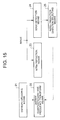
- FIG. 16 is a flowchart showing main steps of a video encoding method according to the present invention.
- an intra prediction direction is selected (step S101)
- intra prediction is performed on an image (step S102)
- a prediction error based on the intra prediction is frequency-transformed and quantized to generate a transform quantization value (step S103)
- the transform quantization value is entropy-encoded (step S104)
- edge information on an image block of the minimum frequency-transform block size of the image is detected (step S105), and the detected edge information is stored in edge information storage means (step S106).
- FIG. 17 is a flowchart showing main steps of a video decoding method according to the present invention.
- a transform quantization value is entropy-decoded (step S201)
- the transform quantization value is inverse-quantized and inverse frequency transform thereof is performed (step S202)
- an intra prediction direction used to decode a block to be decoded is selected based on edge information previously detected (step S203)
- intra prediction is performed on an image (step S204)
- edge information on an image block of the minimum frequency-transform block size of the image is detected (step S205), and the detected edge information is stored in edge information storage means (step S206).
- a video encoding device including: intra prediction means for performing intra prediction on an image; frequency transform/quantization means for frequency-transforming and quantizing a prediction error based on the intra prediction performed by the intra prediction means; entropy encoding means for entropy-encoding a transform quantization value generated by the frequency transform/quantization means; edge detection means for detecting edge information on an image block of the minimum frequency-transform block size of the image; edge information storage means for storing the edge information detected by the edge detection means; and intra prediction direction selecting means for selecting an intra prediction direction used to encode a block to be encoded, based on edge information stored in the edge information storage means, wherein the intra prediction direction selecting means selects the intra prediction direction based on modes of edge information contained in two or more reconstructed images of the minimum frequency-transform block size adjacent to the block to be encoded.
- a video encoding device including: intra prediction means for performing intra prediction on an image; frequency transform/quantization means for frequency-transforming and quantizing a prediction error based on the intra prediction performed by the intra prediction means; entropy encoding means for entropy-encoding a transform quantization value generated by the frequency transform/quantization means; edge detection means for detecting edge information on an image block of the minimum frequency-transform block size of the image; edge information storage means for storing the edge information detected by the edge detection means; and intra prediction direction selecting means for selecting an intra prediction direction used to encode a block to be encoded, based on edge information stored in the edge information storage means, wherein the intra prediction direction selecting means selects the intra prediction direction based on edge information on the largest norm among pieces of edge information contained in two or more reconstructed images of the minimum frequency-transform block size adjacent to the block to be encoded.
- the video encoding device further including encoding control means for performing intra prediction on the image in the intra prediction direction selected by the intra prediction direction selecting means under the condition that an entropy decoder in a video decoding device understands that a predicted intra prediction direction determined based on intra prediction directions of blocks leftwardly and upwardly adjacent to the block to be encoded is DC and that a predicted intra prediction direction of the DC is the intra prediction direction of the block to be encoded.
- a video encoding device including: intra prediction means for performing intra prediction on an image; frequency transform/quantization means for frequency-transforming and quantizing a prediction error based on the intra prediction performed by the intra prediction means; entropy encoding means for entropy-encoding a transform quantization value generated by the frequency transform/quantization means; edge detection means for detecting edge information on an image block of the minimum frequency-transform block size of the image; edge information storage means for storing the edge information detected by the edge detection means; and encoding control means for determining a split block shape of a largest coding unit to be encoded, based on edge information stored in the edge information storage means, wherein the encoding control means determines the split block shape of the largest coding unit using a mode of stored edge information corresponding to an input image of the largest coding unit to be encoded.
- a video decoding device including: entropy decoding means for entropy-decoding a transform quantization value; inverse quantization/inverse frequency transform means for inverse-quantizing the transform quantization value and performing inverse frequency transform thereof; intra prediction means for performing intra prediction on an image; edge detection means for detecting edge information on an image block of the minimum frequency-transform block size of the image; and intra prediction direction selecting means for selecting an intra prediction direction used to decode a block to be decoded, based on the edge information detected by the edge detection means, wherein the intra prediction direction selecting means selects an intra prediction direction based on modes of edge information contained in two or more reconstructed images of the minimum frequency-transform block size adjacent to the block to be decoded.
- a video decoding device including: entropy decoding means for entropy-decoding a transform quantization value; inverse quantization/inverse frequency transform means for inverse-quantizing the transform quantization value and performing inverse frequency transform thereof; intra prediction means for performing intra prediction on an image; edge detection means for detecting edge information on an image block of the minimum frequency-transform block size of the image; and intra prediction direction selecting means for selecting an intra prediction direction used to decode a block to be decoded, based on the edge information detected by the edge detection means, wherein the intra prediction direction selecting means selects an intra prediction direction based on edge information on the largest norm among pieces of edge information contained in two or more reconstructed images of the minimum frequency-transform block size adjacent to the block to be decoded.
- the video decoding device further including decoding control means for performing intra prediction on the image in the intra prediction direction selected by the intra prediction direction selecting means under the condition that the entropy decoder understands that a predicted intra prediction direction determined based on intra prediction directions of blocks leftwardly and upwardly adjacent to the block to be decoded is DC and that a predicted intra prediction direction of the DC is is the intra prediction direction of the block to be decoded.
Landscapes
- Engineering & Computer Science (AREA)
- Multimedia (AREA)
- Signal Processing (AREA)
- Compression Or Coding Systems Of Tv Signals (AREA)
Applications Claiming Priority (2)
| Application Number | Priority Date | Filing Date | Title |
|---|---|---|---|
| JP2010290968 | 2010-12-27 | ||
| PCT/JP2011/007011 WO2012090413A1 (fr) | 2010-12-27 | 2011-12-15 | Dispositif de codage vidéo, dispositif de décodage vidéo, procédé de codage vidéo, procédé de décodage vidéo et programme |
Publications (2)
| Publication Number | Publication Date |
|---|---|
| EP2670141A1 true EP2670141A1 (fr) | 2013-12-04 |
| EP2670141A4 EP2670141A4 (fr) | 2016-03-30 |
Family
ID=46382555
Family Applications (1)
| Application Number | Title | Priority Date | Filing Date |
|---|---|---|---|
| EP11852257.2A Withdrawn EP2670141A4 (fr) | 2010-12-27 | 2011-12-15 | Dispositif de codage vidéo, dispositif de décodage vidéo, procédé de codage vidéo, procédé de décodage vidéo et programme |
Country Status (4)
| Country | Link |
|---|---|
| US (1) | US20130259121A1 (fr) |
| EP (1) | EP2670141A4 (fr) |
| JP (1) | JPWO2012090413A1 (fr) |
| WO (1) | WO2012090413A1 (fr) |
Families Citing this family (8)
| Publication number | Priority date | Publication date | Assignee | Title |
|---|---|---|---|---|
| TW201419862A (zh) * | 2012-11-13 | 2014-05-16 | Hon Hai Prec Ind Co Ltd | 影像切割系統及方法 |
| TW201419864A (zh) * | 2012-11-13 | 2014-05-16 | Hon Hai Prec Ind Co Ltd | 影像切割系統及方法 |
| TW201419865A (zh) * | 2012-11-13 | 2014-05-16 | Hon Hai Prec Ind Co Ltd | 影像切割系統及方法 |
| TW201419863A (zh) * | 2012-11-13 | 2014-05-16 | Hon Hai Prec Ind Co Ltd | 影像切割系統及方法 |
| CN106165417A (zh) | 2014-04-23 | 2016-11-23 | 索尼公司 | 图像处理设备和图像处理方法 |
| JP6148201B2 (ja) * | 2014-05-02 | 2017-06-14 | 日本電信電話株式会社 | イントラ予測方向絞込み方法及びイントラ予測方向絞込み装置 |
| US20170214943A1 (en) * | 2016-01-22 | 2017-07-27 | Mitsubishi Electric Research Laboratories, Inc. | Point Cloud Compression using Prediction and Shape-Adaptive Transforms |
| JP6992825B2 (ja) * | 2018-01-30 | 2022-01-13 | 富士通株式会社 | 映像符号化装置、映像符号化方法、映像復号装置、映像復号方法、及び映像符号化システム |
Family Cites Families (11)
| Publication number | Priority date | Publication date | Assignee | Title |
|---|---|---|---|---|
| US6633611B2 (en) * | 1997-04-24 | 2003-10-14 | Mitsubishi Denki Kabushiki Kaisha | Method and apparatus for region-based moving image encoding and decoding |
| EP2320661B8 (fr) * | 2001-11-29 | 2015-09-02 | Godo Kaisha IP Bridge 1 | Procédé de retrait de distorsion de codage |
| CN1795680B (zh) | 2003-03-03 | 2010-06-16 | 新加坡科技研究局 | 采用avc帧内预测以便对数字视频进行编码的方法和装置 |
| US7706442B2 (en) | 2005-02-15 | 2010-04-27 | Industrial Technology Research Institute | Method for coding mode selection of intra prediction in video compression |
| KR100750145B1 (ko) | 2005-12-12 | 2007-08-21 | 삼성전자주식회사 | 영상의 인트라 예측 부호화, 복호화 방법 및 장치 |
| FR2908007A1 (fr) | 2006-10-31 | 2008-05-02 | Thomson Licensing Sas | Procede de codage d'une sequence d'images |
| JP2009111691A (ja) | 2007-10-30 | 2009-05-21 | Hitachi Ltd | 画像符号化装置及び符号化方法、画像復号化装置及び復号化方法 |
| EP2081386A1 (fr) * | 2008-01-18 | 2009-07-22 | Panasonic Corporation | Prédiction de bord haute précision pour codage intra |
| US8031946B2 (en) * | 2008-03-27 | 2011-10-04 | Texas Instruments Incorporated | Reduced calculations in determining intra-prediction type method and system |
| JP2012089905A (ja) * | 2009-01-13 | 2012-05-10 | Hitachi Ltd | 画像符号化装置および画像符号化方法、画像復号化装置および画像復号化方法 |
| WO2010087157A1 (fr) * | 2009-01-29 | 2010-08-05 | パナソニック株式会社 | Procédé de codage d'image et procédé de décodage d'image |
-
2011
- 2011-12-15 JP JP2012550698A patent/JPWO2012090413A1/ja active Pending
- 2011-12-15 EP EP11852257.2A patent/EP2670141A4/fr not_active Withdrawn
- 2011-12-15 US US13/992,610 patent/US20130259121A1/en not_active Abandoned
- 2011-12-15 WO PCT/JP2011/007011 patent/WO2012090413A1/fr not_active Ceased
Also Published As
| Publication number | Publication date |
|---|---|
| US20130259121A1 (en) | 2013-10-03 |
| JPWO2012090413A1 (ja) | 2014-06-05 |
| EP2670141A4 (fr) | 2016-03-30 |
| WO2012090413A1 (fr) | 2012-07-05 |
Similar Documents
| Publication | Publication Date | Title |
|---|---|---|
| KR102688470B1 (ko) | 영상 부호화/복호화 방법, 장치 및 비트스트림을 저장한 기록 매체 | |
| KR102438021B1 (ko) | 영상 정보 부호화 방법 및 복호화 방법 | |
| US20230135855A1 (en) | Method and apparatus for processing a video signal | |
| JP6870096B2 (ja) | 二次変換を用いたビデオ信号のエンコーディング/デコーディング方法及び装置 | |
| DK3280145T3 (en) | PROCEDURE FOR ENCODING AND DEVICE FOR DECODING PICTURE THROUGH INTRAPHIC PREDICTION. | |
| KR102555352B1 (ko) | 인트라 예측 방법과 이를 이용한 부호화 장치 및 복호화 장치 | |
| KR102928432B1 (ko) | 인트라 예측 모드 기반 영상 처리 방법 및 이를 위한 장치 | |
| EP2868080B1 (fr) | Procédé et dispositif pour coder ou décoder une image | |
| EP2974312B1 (fr) | Dispositif et procédé de codage évolutif d'informations vidéo | |
| CN108632626B (zh) | 推导参考预测模式值的方法 | |
| KR102315455B1 (ko) | 변환에 기반한 영상 코딩 방법 및 그 장치 | |
| US20220191505A1 (en) | Video encoding device, video decoding device, video encoding method, video decoding method, and program using inter prediction | |
| CN112385220A (zh) | 视频编码系统中处理具有分割限制之视频图像的方法和装置 | |
| EP2670141A1 (fr) | Dispositif de codage vidéo, dispositif de décodage vidéo, procédé de codage vidéo, procédé de décodage vidéo et programme | |
| KR102539354B1 (ko) | 인트라 예측 모드 기반 영상 처리 방법 및 이를 위한 장치 | |
| KR20060134976A (ko) | 고급 비디오 코딩을 위한 감소된 해상도의 갱신 모드 | |
| KR20160135226A (ko) | 비디오 코딩에서 인트라 블록 카피를 위한 검색 영역 결정 | |
| KR20160022345A (ko) | 인터-컴포넌트 필터링 | |
| KR20230098714A (ko) | 영상 처리 방법 및 이를 위한 장치 | |
| EP2899976A1 (fr) | Dispositif de codage vidéo, dispositif de décodage vidéo, procédé de codage vidéo, procédé de décodage vidéo et programme | |
| WO2026087534A1 (fr) | Codage et décodage d'image et de vidéo | |
| WO2026087535A1 (fr) | Codage et décodage d'image et de vidéo | |
| KR20220130067A (ko) | 에러에 강인한 인-루프 필터를 이용하는 영상 부호화/복호화 방법과 그에 관한 시그널링 방법 | |
| KR20120058384A (ko) | 인트라 프리딕션 방법 |
Legal Events
| Date | Code | Title | Description |
|---|---|---|---|
| PUAI | Public reference made under article 153(3) epc to a published international application that has entered the european phase |
Free format text: ORIGINAL CODE: 0009012 |
|
| 17P | Request for examination filed |
Effective date: 20130704 |
|
| AK | Designated contracting states |
Kind code of ref document: A1 Designated state(s): AL AT BE BG CH CY CZ DE DK EE ES FI FR GB GR HR HU IE IS IT LI LT LU LV MC MK MT NL NO PL PT RO RS SE SI SK SM TR |
|
| DAX | Request for extension of the european patent (deleted) | ||
| RA4 | Supplementary search report drawn up and despatched (corrected) |
Effective date: 20160225 |
|
| RIC1 | Information provided on ipc code assigned before grant |
Ipc: H04N 19/61 20140101ALN20160219BHEP Ipc: H04N 19/14 20140101ALI20160219BHEP Ipc: H04N 19/176 20140101AFI20160219BHEP Ipc: H04N 19/423 20140101ALN20160219BHEP Ipc: H04N 19/11 20140101ALI20160219BHEP Ipc: H04N 19/593 20140101ALN20160219BHEP |
|
| STAA | Information on the status of an ep patent application or granted ep patent |
Free format text: STATUS: THE APPLICATION IS DEEMED TO BE WITHDRAWN |
|
| 18D | Application deemed to be withdrawn |
Effective date: 20160927 |