EP2670223A2 - Système d'éclairage avec réduction de puissance de veille - Google Patents
Système d'éclairage avec réduction de puissance de veille Download PDFInfo
- Publication number
- EP2670223A2 EP2670223A2 EP20130167075 EP13167075A EP2670223A2 EP 2670223 A2 EP2670223 A2 EP 2670223A2 EP 20130167075 EP20130167075 EP 20130167075 EP 13167075 A EP13167075 A EP 13167075A EP 2670223 A2 EP2670223 A2 EP 2670223A2
- Authority
- EP
- European Patent Office
- Prior art keywords
- supply unit
- standby power
- power supply
- lighting
- voltage
- Prior art date
- Legal status (The legal status is an assumption and is not a legal conclusion. Google has not performed a legal analysis and makes no representation as to the accuracy of the status listed.)
- Granted
Links
Images
Classifications
-
- H—ELECTRICITY
- H05—ELECTRIC TECHNIQUES NOT OTHERWISE PROVIDED FOR
- H05B—ELECTRIC HEATING; ELECTRIC LIGHT SOURCES NOT OTHERWISE PROVIDED FOR; CIRCUIT ARRANGEMENTS FOR ELECTRIC LIGHT SOURCES, IN GENERAL
- H05B45/00—Circuit arrangements for operating light-emitting diodes [LED]
- H05B45/10—Controlling the intensity of the light
-
- H—ELECTRICITY
- H05—ELECTRIC TECHNIQUES NOT OTHERWISE PROVIDED FOR
- H05B—ELECTRIC HEATING; ELECTRIC LIGHT SOURCES NOT OTHERWISE PROVIDED FOR; CIRCUIT ARRANGEMENTS FOR ELECTRIC LIGHT SOURCES, IN GENERAL
- H05B45/00—Circuit arrangements for operating light-emitting diodes [LED]
-
- H—ELECTRICITY
- H02—GENERATION; CONVERSION OR DISTRIBUTION OF ELECTRIC POWER
- H02J—ELECTRIC POWER NETWORKS; CIRCUIT ARRANGEMENTS OR SYSTEMS FOR SUPPLYING OR DISTRIBUTING ELECTRIC POWER; SYSTEMS FOR STORING ELECTRIC ENERGY
- H02J9/00—Circuit arrangements for emergency or stand-by power supply, e.g. for emergency lighting
- H02J9/04—Circuit arrangements for emergency or stand-by power supply, e.g. for emergency lighting in which the distribution system is disconnected from the normal source and connected to a standby source
-
- H—ELECTRICITY
- H05—ELECTRIC TECHNIQUES NOT OTHERWISE PROVIDED FOR
- H05B—ELECTRIC HEATING; ELECTRIC LIGHT SOURCES NOT OTHERWISE PROVIDED FOR; CIRCUIT ARRANGEMENTS FOR ELECTRIC LIGHT SOURCES, IN GENERAL
- H05B45/00—Circuit arrangements for operating light-emitting diodes [LED]
- H05B45/20—Controlling the colour of the light
-
- H—ELECTRICITY
- H05—ELECTRIC TECHNIQUES NOT OTHERWISE PROVIDED FOR
- H05B—ELECTRIC HEATING; ELECTRIC LIGHT SOURCES NOT OTHERWISE PROVIDED FOR; CIRCUIT ARRANGEMENTS FOR ELECTRIC LIGHT SOURCES, IN GENERAL
- H05B45/00—Circuit arrangements for operating light-emitting diodes [LED]
- H05B45/30—Driver circuits
- H05B45/37—Converter circuits
-
- H—ELECTRICITY
- H05—ELECTRIC TECHNIQUES NOT OTHERWISE PROVIDED FOR
- H05B—ELECTRIC HEATING; ELECTRIC LIGHT SOURCES NOT OTHERWISE PROVIDED FOR; CIRCUIT ARRANGEMENTS FOR ELECTRIC LIGHT SOURCES, IN GENERAL
- H05B45/00—Circuit arrangements for operating light-emitting diodes [LED]
- H05B45/50—Circuit arrangements for operating light-emitting diodes [LED] responsive to malfunctions or undesirable behaviour of LEDs; responsive to LED life; Protective circuits
-
- H—ELECTRICITY
- H05—ELECTRIC TECHNIQUES NOT OTHERWISE PROVIDED FOR
- H05B—ELECTRIC HEATING; ELECTRIC LIGHT SOURCES NOT OTHERWISE PROVIDED FOR; CIRCUIT ARRANGEMENTS FOR ELECTRIC LIGHT SOURCES, IN GENERAL
- H05B47/00—Circuit arrangements for operating light sources in general, i.e. where the type of light source is not relevant
- H05B47/10—Controlling the light source
-
- H—ELECTRICITY
- H05—ELECTRIC TECHNIQUES NOT OTHERWISE PROVIDED FOR
- H05B—ELECTRIC HEATING; ELECTRIC LIGHT SOURCES NOT OTHERWISE PROVIDED FOR; CIRCUIT ARRANGEMENTS FOR ELECTRIC LIGHT SOURCES, IN GENERAL
- H05B47/00—Circuit arrangements for operating light sources in general, i.e. where the type of light source is not relevant
- H05B47/10—Controlling the light source
- H05B47/17—Operational modes, e.g. switching from manual to automatic mode or prohibiting specific operations
-
- H—ELECTRICITY
- H05—ELECTRIC TECHNIQUES NOT OTHERWISE PROVIDED FOR
- H05B—ELECTRIC HEATING; ELECTRIC LIGHT SOURCES NOT OTHERWISE PROVIDED FOR; CIRCUIT ARRANGEMENTS FOR ELECTRIC LIGHT SOURCES, IN GENERAL
- H05B47/00—Circuit arrangements for operating light sources in general, i.e. where the type of light source is not relevant
- H05B47/10—Controlling the light source
- H05B47/175—Controlling the light source by remote control
- H05B47/19—Controlling the light source by remote control via wireless transmission
-
- H—ELECTRICITY
- H05—ELECTRIC TECHNIQUES NOT OTHERWISE PROVIDED FOR
- H05B—ELECTRIC HEATING; ELECTRIC LIGHT SOURCES NOT OTHERWISE PROVIDED FOR; CIRCUIT ARRANGEMENTS FOR ELECTRIC LIGHT SOURCES, IN GENERAL
- H05B47/00—Circuit arrangements for operating light sources in general, i.e. where the type of light source is not relevant
- H05B47/20—Responsive to malfunctions or to light source life; for protection
-
- H—ELECTRICITY
- H02—GENERATION; CONVERSION OR DISTRIBUTION OF ELECTRIC POWER
- H02J—ELECTRIC POWER NETWORKS; CIRCUIT ARRANGEMENTS OR SYSTEMS FOR SUPPLYING OR DISTRIBUTING ELECTRIC POWER; SYSTEMS FOR STORING ELECTRIC ENERGY
- H02J2207/00—Details of circuit arrangements for charging or discharging batteries or supplying loads from batteries
- H02J2207/50—Charging of capacitors, supercapacitors, ultra-capacitors or double layer capacitors
-
- Y—GENERAL TAGGING OF NEW TECHNOLOGICAL DEVELOPMENTS; GENERAL TAGGING OF CROSS-SECTIONAL TECHNOLOGIES SPANNING OVER SEVERAL SECTIONS OF THE IPC; TECHNICAL SUBJECTS COVERED BY FORMER USPC CROSS-REFERENCE ART COLLECTIONS [XRACs] AND DIGESTS
- Y02—TECHNOLOGIES OR APPLICATIONS FOR MITIGATION OR ADAPTATION AGAINST CLIMATE CHANGE
- Y02B—CLIMATE CHANGE MITIGATION TECHNOLOGIES RELATED TO BUILDINGS, e.g. HOUSING, HOUSE APPLIANCES OR RELATED END-USER APPLICATIONS
- Y02B20/00—Energy efficient lighting technologies, e.g. halogen lamps or gas discharge lamps
- Y02B20/30—Semiconductor lamps, e.g. solid state lamps [SSL] light emitting diodes [LED] or organic LED [OLED]
Definitions
- the embodiment relates to a lighting system with reduced standby power. More particularly, the embodiment relates to a standby power cut-off system using wireless communication.
- Standby power refers to power being consumed even after a power source is switched off, that is, electric energy being continuously consumed regardless of the operation of electric appliances.
- a lighting device employs a dimmer to properly maintain intensity of lighting according to indoor environment and to reduce unnecessary power consumption.
- the dimmer is connected to the lighting device to control the on/off operation, the lighting level, and the color temperature level of the lighting device.
- the embodiment provides a lighting system with reduced standby power.
- a lighting system with reduced standby power includes a main control unit to control a lighting device according to a control signal; a driver connected to the main control unit to supply the control signal to the lighting device; and an AC-DC converting circuit to supply power to the driver, wherein the main control unit includes a lighting control unit to control the lighting device; a standby power supply unit to supply standby power; and a power control unit to maintain a voltage or a current of the standby power supply unit in a predetermined level.
- a method of reducing standby power includes charging a standby power supply unit with power supplied from an AC-DC converting circuit in a normal mode; checking whether a lighting off signal is transmitted from an outside and switching off a lighting, and simultaneously, shutting off the power supplied from the AC-DC converting circuit when the lighting off signal is transmitted; changing an operation mode of a lighting device from a normal mode to a standby mode; checking whether a voltage of the standby power supply unit is less than a predetermined level by sensing the voltage of the standby power supply unit; and charging the standby power supply unit when the voltage of the standby power supply unit is less than the predetermined level.
- the standby power supply unit is charged by periodically checking the voltage or a current of the standby power supply unit that provides the standby power so that the standby power can be effectively reduced.
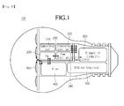
- FIG. 1 is a block diagram of a lighting system according to the embodiment.
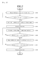
- FIG. 2 is a flowchart showing a method of reducing standby power of a lighting system according to the embodiment.
- FIG. 1 is a block diagram of a lighting system according to the embodiment.
- the lighting system 100 includes a main control unit 200, a DC supply unit 300, a driver 400, a lighting 450 and an AC-DC converting circuit 500.
- FIG. 1 The embodiment is shown in FIG. 1 as a block diagram in which a diode, a condenser, a coil, a resistor, a switching device and a microprocessor constituting main components of the embodiment are omitted because the embodiment may be easily embodied by those skilled in the art based on the block diagram, so the detailed circuit diagram will be omitted.
- the main control unit 200 includes a communication unit 210, a lighting control unit 220, a standby power supply unit 230 and a power control unit 240.
- the communication unit 210 may perform wireless communication with external devices. For instance, when a lighting control signal, such as a lighting level signal or a color temperature level signal, is input from the outside, the communication unit 210 transfers the alighting control signal to the lighting control unit 220 to control the intensity of lighting (brightness) and the color temperature of the lighting 450 according to the lighting control signal.
- the wireless communication may be performed, for instance, through the radio frequency (RF) scheme.
- RF radio frequency
- the lighting control unit 220 is connected to the communication unit 210 to control the power supplied to the lighting 450.
- the lighting control unit 220 is connected to the driver 400 and transfers the lighting control signal received from the outside to the driver 400 to control the brightness and the color temperature of the lighting 450 according to the lighting control signal.
- the lighting control signal may be a dimming signal.
- the lighting control unit 220 When a lighting off signal is input from the outside, the lighting control unit 220 turns off the lighting 450 by controlling the driver 400. In addition, the lighting control unit 220 changes the operation mode of the power control unit 240 to the standby mode. In the standby mode, the power control unit 240 is connected to the standby power supply unit 230 and the standby power supply unit 230 is charged for standby time by sensing the voltage of the standby power supply unit 230.
- the power control unit 240 checks the voltage of the standby power supply unit 230 in a predetermined time interval and drives the DC supply unit 300 when a voltage value of the standby power supply unit 230 is lower than a predetermined value to charge the standby power supply unit 230 with the voltage supplied from the DC supply unit 300.
- the power control unit 240 controls the DC supply unit 300 to operate in the normal mode from the standby mode such that the standby power supply unit 230 can be charged with the voltage having the predetermined value or more.
- the power control unit 240 supplies a control signal to stop the operation of the DC supply unit 300 so that the operation mode of the DC supply unit 300 may be changed from the normal mode to the standby mode.
- the standby power supply unit 230 is connected to the power control unit 240 and the communication unit 210 to supply standby power required for receiving the control signal from the outside to the communication unit 210.
- the standby power supply unit 230 may include a super capacitor.
- the DC supply unit 300 is connected to the AC-DC converting circuit 500 to use DC power output from the AC-DC converting circuit 500 so that the standby power supply unit 230 can be charged without a separate driving power source.
- the standby power can be supplied by sensing the voltage in a predetermined time interval as described above when the power is supplied.
- the driver 400 is connected to the lighting 450 to supply power to the lighting 450. If necessary, the user can adjust the brightness of the lighting 450 by controlling the power supplied to the lighting 450.
- the lighting 450 may include a light emitting diode LED, but the embodiment is not limited thereto.
- the AC-DC converting circuit 500 converts input AC power into DC power and transfers the DC power to the driver 400 and may include a diode.
- the standby power supply unit 230 and the power control unit 240 may be integrally formed with each other in the lighting system 100.
- the voltage of the standby power supply unit 230 can be maintained in a predetermined level or more by sensing the voltage of the standby power supply unit 230 in a predetermined time interval even when the operation is finished as well as in the normal operation mode, so that the consumption of the standby power may be reduced even if the power source for the lighting 450 is switched off.
- FIG. 2 is a flowchart showing a method of reducing standby power of the lighting system according to the embodiment.
- the power supplied from the AC-DC converting circuit 500 is charged in the standby power supply unit 230 (S100). At this time, the power supplied from the AC-DC converting circuit 500 is also supplied to the driver 400.
- the communication unit 210 determines whether the lighting off signal is transmitted from the outside (S101). If the lighting off signal is transmitted from the outside, the lighting 450 is switched off through the lighting control unit 220 and the power supplied from the AC-DC converting circuit 500 is shut off (S102).
- the lighting control unit 220 changes the operation mode of the lighting device from the normal mode to the standby mode (S103). If the operation mode of the lighting device is changed to the standby mode, the communication unit 210 receives the standby power from the standby power supply unit 230.
- the power control unit 240 periodically checks the voltage of the standby power supply unit 230 (S104).
- step S105 If it is determined in step S105 that the voltage of the standby power supply unit 230 is less than the predetermined value, the power control unit 240 changes the operation mode of the DC supply unit 300 from the standby mode to the normal mode to charge the standby power supply unit 230 (S106).
- the operation mode of the lighting system 100 is the standby mode
- the voltage state of the standby power supply unit 230 is periodically checked and the operation mode of the DC supply unit 300 is changed from the standby mode to the normal mode when the voltage of the standby power supply unit 230 is less than the predetermined value in order to charge the standby power supply unit 230.
- the power control unit 240 checks whether the voltage of the standby power supply unit 230 is more than the predetermined level (S107). If the voltage of the standby power supply unit 230 is more than the predetermined level, the operation mode of the DC supply unit 300 is changed again to the standby mode (S108).
Landscapes
- Engineering & Computer Science (AREA)
- Computer Networks & Wireless Communication (AREA)
- Business, Economics & Management (AREA)
- Emergency Management (AREA)
- Power Engineering (AREA)
- Circuit Arrangement For Electric Light Sources In General (AREA)
- Dc-Dc Converters (AREA)
- Stand-By Power Supply Arrangements (AREA)
Applications Claiming Priority (1)
| Application Number | Priority Date | Filing Date | Title |
|---|---|---|---|
| KR20120058891A KR101360685B1 (ko) | 2012-05-31 | 2012-05-31 | 대기전력 절감 조명 시스템 |
Publications (3)
| Publication Number | Publication Date |
|---|---|
| EP2670223A2 true EP2670223A2 (fr) | 2013-12-04 |
| EP2670223A3 EP2670223A3 (fr) | 2014-11-12 |
| EP2670223B1 EP2670223B1 (fr) | 2017-03-22 |
Family
ID=48534140
Family Applications (1)
| Application Number | Title | Priority Date | Filing Date |
|---|---|---|---|
| EP13167075.4A Not-in-force EP2670223B1 (fr) | 2012-05-31 | 2013-05-08 | Système d'éclairage avec réduction de puissance de veille |
Country Status (5)
| Country | Link |
|---|---|
| US (1) | US9137876B2 (fr) |
| EP (1) | EP2670223B1 (fr) |
| JP (1) | JP6219599B2 (fr) |
| KR (1) | KR101360685B1 (fr) |
| CN (1) | CN103458566A (fr) |
Cited By (3)
| Publication number | Priority date | Publication date | Assignee | Title |
|---|---|---|---|---|
| WO2015189031A1 (fr) * | 2014-06-10 | 2015-12-17 | Koninklijke Philips N.V. | Commande de circuit d'éclairage à commande sans fil |
| WO2016064485A1 (fr) * | 2014-10-21 | 2016-04-28 | General Electric Company | Mode rafale de microcontrôleur pour maintenir une alimentation en tension d'un système d'éclairage en mode veille |
| GB2618904A (en) * | 2022-04-22 | 2023-11-22 | Electronic Theatre Controls Inc | Low power standby mode for luminaire |
Families Citing this family (4)
| Publication number | Priority date | Publication date | Assignee | Title |
|---|---|---|---|---|
| KR101360685B1 (ko) * | 2012-05-31 | 2014-02-10 | 엘지이노텍 주식회사 | 대기전력 절감 조명 시스템 |
| WO2016110833A2 (fr) | 2015-01-06 | 2016-07-14 | Cmoo Systems Itd. | Procédé et appareil d'extraction d'énergie dans une infrastructure de câblage ca préexistante |
| JP7022944B2 (ja) * | 2017-09-01 | 2022-02-21 | パナソニックIpマネジメント株式会社 | 照明システム及びコントローラ |
| KR102106079B1 (ko) | 2019-09-17 | 2020-04-29 | 조현희 | 대기전력 차단 전기공사 시공방법 |
Family Cites Families (26)
| Publication number | Priority date | Publication date | Assignee | Title |
|---|---|---|---|---|
| DE19516052A1 (de) * | 1995-05-04 | 1996-11-14 | Eta Plus Electronic Gmbh U Co | Verfahren zum Betreiben einer Hochdruckgasentladungslampe und Schaltungsanordnung zur Durchführung des Verfahrens |
| JP3620347B2 (ja) * | 1999-06-15 | 2005-02-16 | 松下電工株式会社 | 熱線センサ付自動スイッチ |
| US8972052B2 (en) * | 2004-07-07 | 2015-03-03 | Irobot Corporation | Celestial navigation system for an autonomous vehicle |
| US8491159B2 (en) * | 2006-03-28 | 2013-07-23 | Wireless Environment, Llc | Wireless emergency lighting system |
| US8829799B2 (en) * | 2006-03-28 | 2014-09-09 | Wireless Environment, Llc | Autonomous grid shifting lighting device |
| US7902767B2 (en) * | 2006-12-29 | 2011-03-08 | Westinghouse Digital, Llc | AC inverter capable of driving multiple lamps for LCD panel backlight |
| TW200906223A (en) * | 2007-07-30 | 2009-02-01 | Topco Technologies Corp | Illumination system |
| WO2009027962A2 (fr) * | 2007-09-02 | 2009-03-05 | Orziv - Design And Development | Système de rattrapage pour interrupteur électrique télécommandé |
| US8593072B2 (en) * | 2007-11-13 | 2013-11-26 | Osram Gesellschaft Mit Beschraenkter Haftung | Circuit assembly and method for operating a high pressure discharge lamp |
| JP2009283312A (ja) * | 2008-05-22 | 2009-12-03 | Toshiba Corp | 照明制御システム |
| JP2010056614A (ja) * | 2008-08-26 | 2010-03-11 | Panasonic Electric Works Co Ltd | 負荷制御システム |
| US8957601B2 (en) * | 2008-09-18 | 2015-02-17 | Lumastream Canada Ulc | Configurable LED driver/dimmer for solid state lighting applications |
| CA2768518A1 (fr) * | 2009-08-21 | 2011-02-24 | Osram Sylvania Inc. | Onduleur resonant dote d'un circuit de veille |
| US8704450B2 (en) * | 2010-02-26 | 2014-04-22 | Triune Ip, Llc | Flash LED controller |
| KR20110122987A (ko) * | 2010-05-06 | 2011-11-14 | (주)대우건설 | 대기전력, 온도조절 및 조명제어가 가능한 통합스위칭장치 및 그 방법 |
| US8729811B2 (en) * | 2010-07-30 | 2014-05-20 | Cirrus Logic, Inc. | Dimming multiple lighting devices by alternating energy transfer from a magnetic storage element |
| JP5853418B2 (ja) * | 2011-05-20 | 2016-02-09 | 株式会社リコー | 光源駆動装置及び画像形成装置 |
| JP5829067B2 (ja) * | 2011-07-11 | 2015-12-09 | ローム株式会社 | Led駆動装置、照明装置、液晶表示装置 |
| EP3554195A1 (fr) * | 2012-03-09 | 2019-10-16 | Signify Holding B.V. | Source lumineuse à del |
| US20130257293A1 (en) * | 2012-03-30 | 2013-10-03 | Deeder Mohammad Aurongzeb | Automatic system enabled daylight sensor |
| GB2501770B (en) * | 2012-05-04 | 2016-03-16 | Litonics Ltd | Lighting device |
| KR101360685B1 (ko) * | 2012-05-31 | 2014-02-10 | 엘지이노텍 주식회사 | 대기전력 절감 조명 시스템 |
| US9066398B2 (en) * | 2012-11-15 | 2015-06-23 | Shenzhen China Star Optoelectronics Technology Co., Ltd. | Method for reducing standby power consumption |
| US9524633B2 (en) * | 2013-03-14 | 2016-12-20 | Lutron Electronics Co., Inc. | Remote control having a capacitive touch surface and a mechanism for awakening the remote control |
| US9537407B2 (en) * | 2013-05-22 | 2017-01-03 | Cree, Inc. | Power supply with standby operation |
| US9629220B2 (en) * | 2013-08-05 | 2017-04-18 | Peter Panopoulos | Sensor-based controllable LED lighting system with repositionable components and method |
-
2012
- 2012-05-31 KR KR20120058891A patent/KR101360685B1/ko not_active Expired - Fee Related
-
2013
- 2013-05-08 EP EP13167075.4A patent/EP2670223B1/fr not_active Not-in-force
- 2013-05-23 US US13/901,141 patent/US9137876B2/en active Active
- 2013-05-27 JP JP2013110815A patent/JP6219599B2/ja not_active Expired - Fee Related
- 2013-05-31 CN CN2013102139438A patent/CN103458566A/zh active Pending
Non-Patent Citations (1)
| Title |
|---|
| None |
Cited By (8)
| Publication number | Priority date | Publication date | Assignee | Title |
|---|---|---|---|---|
| WO2015189031A1 (fr) * | 2014-06-10 | 2015-12-17 | Koninklijke Philips N.V. | Commande de circuit d'éclairage à commande sans fil |
| US10091864B2 (en) | 2014-06-10 | 2018-10-02 | Philips Lighting Holding B.V. | Driving a light circuit with wireless control |
| RU2682180C2 (ru) * | 2014-06-10 | 2019-03-15 | Филипс Лайтинг Холдинг Б.В. | Возбуждение световой цепи посредством беспроводного управления |
| WO2016064485A1 (fr) * | 2014-10-21 | 2016-04-28 | General Electric Company | Mode rafale de microcontrôleur pour maintenir une alimentation en tension d'un système d'éclairage en mode veille |
| US9380664B2 (en) * | 2014-10-21 | 2016-06-28 | General Electric Company | Microcontroller burst mode to maintain voltage supply during standby mode of a lighting system |
| GB2618904A (en) * | 2022-04-22 | 2023-11-22 | Electronic Theatre Controls Inc | Low power standby mode for luminaire |
| DE102023109776B4 (de) | 2022-04-22 | 2025-01-09 | Electronic Theatre Controls, Inc. | Standby-energiesparmodus für leuchte |
| US12389511B2 (en) | 2022-04-22 | 2025-08-12 | Electronic Theatre Controls, Inc. | Low power standby mode for luminaire |
Also Published As
| Publication number | Publication date |
|---|---|
| EP2670223A3 (fr) | 2014-11-12 |
| US20130320866A1 (en) | 2013-12-05 |
| EP2670223B1 (fr) | 2017-03-22 |
| JP2013251260A (ja) | 2013-12-12 |
| CN103458566A (zh) | 2013-12-18 |
| US9137876B2 (en) | 2015-09-15 |
| KR20130134961A (ko) | 2013-12-10 |
| KR101360685B1 (ko) | 2014-02-10 |
| JP6219599B2 (ja) | 2017-10-25 |
Similar Documents
| Publication | Publication Date | Title |
|---|---|---|
| US9137876B2 (en) | Lighting system with reduced standby power | |
| US10333341B2 (en) | LED lighting system with battery for demand management and emergency lighting | |
| TWI483513B (zh) | 裝備電源供應單元之電氣裝置 | |
| US8854838B2 (en) | Power supply control device, power supply system and eletronic device | |
| US11146169B2 (en) | Power factor correction for LED drivers | |
| US10063091B2 (en) | Standby power saving circuit | |
| US9635720B2 (en) | Alternating current (AC)-direct current (DC) power booster and AC-DC power control module for AC and DC illuminations | |
| US9136753B2 (en) | Electric device having low power consumption in the stand-by state | |
| EP3516930B1 (fr) | Diode électroluminescente de rattrapage, del, tube permettant une gradation par paliers dans un système d'éclairage à luminaire multilampes | |
| US9801246B2 (en) | Dimmable LED light | |
| KR101594699B1 (ko) | 교류 전력선 통신 장치 | |
| CN104053275A (zh) | 照明装置 | |
| KR101144969B1 (ko) | 대기 전력이 절감되는 무선 장치 및 그 무선 장치의 대기 전력 절감 방법 | |
| CN205124053U (zh) | 开关控制系统 | |
| KR101964628B1 (ko) | 별도의 배선추가 없이 교류전원 벽스위치를 이용한 led 조명제어장치 및 그 제어 방법 | |
| TWI733469B (zh) | 負載控制裝置、負載控制方法及程式 | |
| WO2009136590A1 (fr) | Unité d'alimentation électrique | |
| CN105282927A (zh) | 开关控制系统及其工作方法 | |
| KR101519812B1 (ko) | 조명 장치 | |
| KR20090051545A (ko) | 지그비 모뎀을 이용한 조명등 원격 제어 회로 | |
| HK1248443A1 (en) | Multifunction electronic power supply for led lighting appliances |
Legal Events
| Date | Code | Title | Description |
|---|---|---|---|
| PUAI | Public reference made under article 153(3) epc to a published international application that has entered the european phase |
Free format text: ORIGINAL CODE: 0009012 |
|
| AK | Designated contracting states |
Kind code of ref document: A2 Designated state(s): AL AT BE BG CH CY CZ DE DK EE ES FI FR GB GR HR HU IE IS IT LI LT LU LV MC MK MT NL NO PL PT RO RS SE SI SK SM TR |
|
| AX | Request for extension of the european patent |
Extension state: BA ME |
|
| PUAL | Search report despatched |
Free format text: ORIGINAL CODE: 0009013 |
|
| AK | Designated contracting states |
Kind code of ref document: A3 Designated state(s): AL AT BE BG CH CY CZ DE DK EE ES FI FR GB GR HR HU IE IS IT LI LT LU LV MC MK MT NL NO PL PT RO RS SE SI SK SM TR |
|
| AX | Request for extension of the european patent |
Extension state: BA ME |
|
| RIC1 | Information provided on ipc code assigned before grant |
Ipc: H05B 37/02 20060101AFI20141007BHEP |
|
| 17P | Request for examination filed |
Effective date: 20150418 |
|
| RBV | Designated contracting states (corrected) |
Designated state(s): AL AT BE BG CH CY CZ DE DK EE ES FI FR GB GR HR HU IE IS IT LI LT LU LV MC MK MT NL NO PL PT RO RS SE SI SK SM TR |
|
| GRAP | Despatch of communication of intention to grant a patent |
Free format text: ORIGINAL CODE: EPIDOSNIGR1 |
|
| INTG | Intention to grant announced |
Effective date: 20161004 |
|
| RIN1 | Information on inventor provided before grant (corrected) |
Inventor name: CHUNG, WON SUK |
|
| GRAS | Grant fee paid |
Free format text: ORIGINAL CODE: EPIDOSNIGR3 |
|
| GRAA | (expected) grant |
Free format text: ORIGINAL CODE: 0009210 |
|
| AK | Designated contracting states |
Kind code of ref document: B1 Designated state(s): AL AT BE BG CH CY CZ DE DK EE ES FI FR GB GR HR HU IE IS IT LI LT LU LV MC MK MT NL NO PL PT RO RS SE SI SK SM TR |
|
| REG | Reference to a national code |
Ref country code: GB Ref legal event code: FG4D |
|
| REG | Reference to a national code |
Ref country code: CH Ref legal event code: EP |
|
| REG | Reference to a national code |
Ref country code: AT Ref legal event code: REF Ref document number: 878879 Country of ref document: AT Kind code of ref document: T Effective date: 20170415 |
|
| REG | Reference to a national code |
Ref country code: IE Ref legal event code: FG4D |
|
| REG | Reference to a national code |
Ref country code: DE Ref legal event code: R096 Ref document number: 602013018793 Country of ref document: DE |
|
| RAP2 | Party data changed (patent owner data changed or rights of a patent transferred) |
Owner name: LG INNOTEK CO., LTD. |
|
| REG | Reference to a national code |
Ref country code: NL Ref legal event code: FP |
|
| PG25 | Lapsed in a contracting state [announced via postgrant information from national office to epo] |
Ref country code: NO Free format text: LAPSE BECAUSE OF FAILURE TO SUBMIT A TRANSLATION OF THE DESCRIPTION OR TO PAY THE FEE WITHIN THE PRESCRIBED TIME-LIMIT Effective date: 20170622 Ref country code: LT Free format text: LAPSE BECAUSE OF FAILURE TO SUBMIT A TRANSLATION OF THE DESCRIPTION OR TO PAY THE FEE WITHIN THE PRESCRIBED TIME-LIMIT Effective date: 20170322 Ref country code: GR Free format text: LAPSE BECAUSE OF FAILURE TO SUBMIT A TRANSLATION OF THE DESCRIPTION OR TO PAY THE FEE WITHIN THE PRESCRIBED TIME-LIMIT Effective date: 20170623 Ref country code: HR Free format text: LAPSE BECAUSE OF FAILURE TO SUBMIT A TRANSLATION OF THE DESCRIPTION OR TO PAY THE FEE WITHIN THE PRESCRIBED TIME-LIMIT Effective date: 20170322 Ref country code: FI Free format text: LAPSE BECAUSE OF FAILURE TO SUBMIT A TRANSLATION OF THE DESCRIPTION OR TO PAY THE FEE WITHIN THE PRESCRIBED TIME-LIMIT Effective date: 20170322 |
|
| REG | Reference to a national code |
Ref country code: LT Ref legal event code: MG4D |
|
| REG | Reference to a national code |
Ref country code: AT Ref legal event code: MK05 Ref document number: 878879 Country of ref document: AT Kind code of ref document: T Effective date: 20170322 |
|
| PG25 | Lapsed in a contracting state [announced via postgrant information from national office to epo] |
Ref country code: LU Free format text: LAPSE BECAUSE OF NON-PAYMENT OF DUE FEES Effective date: 20170531 Ref country code: BG Free format text: LAPSE BECAUSE OF FAILURE TO SUBMIT A TRANSLATION OF THE DESCRIPTION OR TO PAY THE FEE WITHIN THE PRESCRIBED TIME-LIMIT Effective date: 20170622 Ref country code: LV Free format text: LAPSE BECAUSE OF FAILURE TO SUBMIT A TRANSLATION OF THE DESCRIPTION OR TO PAY THE FEE WITHIN THE PRESCRIBED TIME-LIMIT Effective date: 20170322 Ref country code: RS Free format text: LAPSE BECAUSE OF FAILURE TO SUBMIT A TRANSLATION OF THE DESCRIPTION OR TO PAY THE FEE WITHIN THE PRESCRIBED TIME-LIMIT Effective date: 20170322 Ref country code: SE Free format text: LAPSE BECAUSE OF FAILURE TO SUBMIT A TRANSLATION OF THE DESCRIPTION OR TO PAY THE FEE WITHIN THE PRESCRIBED TIME-LIMIT Effective date: 20170322 |
|
| PG25 | Lapsed in a contracting state [announced via postgrant information from national office to epo] |
Ref country code: RO Free format text: LAPSE BECAUSE OF FAILURE TO SUBMIT A TRANSLATION OF THE DESCRIPTION OR TO PAY THE FEE WITHIN THE PRESCRIBED TIME-LIMIT Effective date: 20170322 Ref country code: EE Free format text: LAPSE BECAUSE OF FAILURE TO SUBMIT A TRANSLATION OF THE DESCRIPTION OR TO PAY THE FEE WITHIN THE PRESCRIBED TIME-LIMIT Effective date: 20170322 Ref country code: IT Free format text: LAPSE BECAUSE OF FAILURE TO SUBMIT A TRANSLATION OF THE DESCRIPTION OR TO PAY THE FEE WITHIN THE PRESCRIBED TIME-LIMIT Effective date: 20170322 Ref country code: CZ Free format text: LAPSE BECAUSE OF FAILURE TO SUBMIT A TRANSLATION OF THE DESCRIPTION OR TO PAY THE FEE WITHIN THE PRESCRIBED TIME-LIMIT Effective date: 20170322 Ref country code: AT Free format text: LAPSE BECAUSE OF FAILURE TO SUBMIT A TRANSLATION OF THE DESCRIPTION OR TO PAY THE FEE WITHIN THE PRESCRIBED TIME-LIMIT Effective date: 20170322 Ref country code: ES Free format text: LAPSE BECAUSE OF FAILURE TO SUBMIT A TRANSLATION OF THE DESCRIPTION OR TO PAY THE FEE WITHIN THE PRESCRIBED TIME-LIMIT Effective date: 20170322 Ref country code: SK Free format text: LAPSE BECAUSE OF FAILURE TO SUBMIT A TRANSLATION OF THE DESCRIPTION OR TO PAY THE FEE WITHIN THE PRESCRIBED TIME-LIMIT Effective date: 20170322 |
|
| PG25 | Lapsed in a contracting state [announced via postgrant information from national office to epo] |
Ref country code: IS Free format text: LAPSE BECAUSE OF FAILURE TO SUBMIT A TRANSLATION OF THE DESCRIPTION OR TO PAY THE FEE WITHIN THE PRESCRIBED TIME-LIMIT Effective date: 20170722 Ref country code: PL Free format text: LAPSE BECAUSE OF FAILURE TO SUBMIT A TRANSLATION OF THE DESCRIPTION OR TO PAY THE FEE WITHIN THE PRESCRIBED TIME-LIMIT Effective date: 20170322 Ref country code: SM Free format text: LAPSE BECAUSE OF FAILURE TO SUBMIT A TRANSLATION OF THE DESCRIPTION OR TO PAY THE FEE WITHIN THE PRESCRIBED TIME-LIMIT Effective date: 20170322 Ref country code: PT Free format text: LAPSE BECAUSE OF FAILURE TO SUBMIT A TRANSLATION OF THE DESCRIPTION OR TO PAY THE FEE WITHIN THE PRESCRIBED TIME-LIMIT Effective date: 20170724 |
|
| REG | Reference to a national code |
Ref country code: CH Ref legal event code: PL |
|
| REG | Reference to a national code |
Ref country code: DE Ref legal event code: R097 Ref document number: 602013018793 Country of ref document: DE |
|
| PLBE | No opposition filed within time limit |
Free format text: ORIGINAL CODE: 0009261 |
|
| STAA | Information on the status of an ep patent application or granted ep patent |
Free format text: STATUS: NO OPPOSITION FILED WITHIN TIME LIMIT |
|
| PG25 | Lapsed in a contracting state [announced via postgrant information from national office to epo] |
Ref country code: MC Free format text: LAPSE BECAUSE OF FAILURE TO SUBMIT A TRANSLATION OF THE DESCRIPTION OR TO PAY THE FEE WITHIN THE PRESCRIBED TIME-LIMIT Effective date: 20170322 Ref country code: DK Free format text: LAPSE BECAUSE OF FAILURE TO SUBMIT A TRANSLATION OF THE DESCRIPTION OR TO PAY THE FEE WITHIN THE PRESCRIBED TIME-LIMIT Effective date: 20170322 |
|
| REG | Reference to a national code |
Ref country code: IE Ref legal event code: MM4A |
|
| 26N | No opposition filed |
Effective date: 20180102 |
|
| PG25 | Lapsed in a contracting state [announced via postgrant information from national office to epo] |
Ref country code: LI Free format text: LAPSE BECAUSE OF NON-PAYMENT OF DUE FEES Effective date: 20170531 Ref country code: CH Free format text: LAPSE BECAUSE OF NON-PAYMENT OF DUE FEES Effective date: 20170531 Ref country code: SI Free format text: LAPSE BECAUSE OF FAILURE TO SUBMIT A TRANSLATION OF THE DESCRIPTION OR TO PAY THE FEE WITHIN THE PRESCRIBED TIME-LIMIT Effective date: 20170322 |
|
| REG | Reference to a national code |
Ref country code: FR Ref legal event code: ST Effective date: 20180131 |
|
| PG25 | Lapsed in a contracting state [announced via postgrant information from national office to epo] |
Ref country code: LU Free format text: LAPSE BECAUSE OF NON-PAYMENT OF DUE FEES Effective date: 20170508 |
|
| REG | Reference to a national code |
Ref country code: BE Ref legal event code: MM Effective date: 20170531 |
|
| PG25 | Lapsed in a contracting state [announced via postgrant information from national office to epo] |
Ref country code: IE Free format text: LAPSE BECAUSE OF NON-PAYMENT OF DUE FEES Effective date: 20170508 |
|
| PG25 | Lapsed in a contracting state [announced via postgrant information from national office to epo] |
Ref country code: FR Free format text: LAPSE BECAUSE OF NON-PAYMENT OF DUE FEES Effective date: 20170531 |
|
| PG25 | Lapsed in a contracting state [announced via postgrant information from national office to epo] |
Ref country code: BE Free format text: LAPSE BECAUSE OF NON-PAYMENT OF DUE FEES Effective date: 20170531 |
|
| PG25 | Lapsed in a contracting state [announced via postgrant information from national office to epo] |
Ref country code: MT Free format text: LAPSE BECAUSE OF NON-PAYMENT OF DUE FEES Effective date: 20170508 |
|
| PG25 | Lapsed in a contracting state [announced via postgrant information from national office to epo] |
Ref country code: HU Free format text: LAPSE BECAUSE OF FAILURE TO SUBMIT A TRANSLATION OF THE DESCRIPTION OR TO PAY THE FEE WITHIN THE PRESCRIBED TIME-LIMIT; INVALID AB INITIO Effective date: 20130508 |
|
| PGFP | Annual fee paid to national office [announced via postgrant information from national office to epo] |
Ref country code: NL Payment date: 20190408 Year of fee payment: 7 |
|
| PGFP | Annual fee paid to national office [announced via postgrant information from national office to epo] |
Ref country code: DE Payment date: 20190405 Year of fee payment: 7 |
|
| PG25 | Lapsed in a contracting state [announced via postgrant information from national office to epo] |
Ref country code: CY Free format text: LAPSE BECAUSE OF NON-PAYMENT OF DUE FEES Effective date: 20170322 |
|
| PGFP | Annual fee paid to national office [announced via postgrant information from national office to epo] |
Ref country code: GB Payment date: 20190405 Year of fee payment: 7 |
|
| PG25 | Lapsed in a contracting state [announced via postgrant information from national office to epo] |
Ref country code: MK Free format text: LAPSE BECAUSE OF FAILURE TO SUBMIT A TRANSLATION OF THE DESCRIPTION OR TO PAY THE FEE WITHIN THE PRESCRIBED TIME-LIMIT Effective date: 20170322 |
|
| PG25 | Lapsed in a contracting state [announced via postgrant information from national office to epo] |
Ref country code: TR Free format text: LAPSE BECAUSE OF FAILURE TO SUBMIT A TRANSLATION OF THE DESCRIPTION OR TO PAY THE FEE WITHIN THE PRESCRIBED TIME-LIMIT Effective date: 20170322 |
|
| PG25 | Lapsed in a contracting state [announced via postgrant information from national office to epo] |
Ref country code: AL Free format text: LAPSE BECAUSE OF FAILURE TO SUBMIT A TRANSLATION OF THE DESCRIPTION OR TO PAY THE FEE WITHIN THE PRESCRIBED TIME-LIMIT Effective date: 20170322 |
|
| REG | Reference to a national code |
Ref country code: DE Ref legal event code: R119 Ref document number: 602013018793 Country of ref document: DE |
|
| REG | Reference to a national code |
Ref country code: NL Ref legal event code: MM Effective date: 20200601 |
|
| PG25 | Lapsed in a contracting state [announced via postgrant information from national office to epo] |
Ref country code: NL Free format text: LAPSE BECAUSE OF NON-PAYMENT OF DUE FEES Effective date: 20200601 |
|
| GBPC | Gb: european patent ceased through non-payment of renewal fee |
Effective date: 20200508 |
|
| PG25 | Lapsed in a contracting state [announced via postgrant information from national office to epo] |
Ref country code: GB Free format text: LAPSE BECAUSE OF NON-PAYMENT OF DUE FEES Effective date: 20200508 |
|
| PG25 | Lapsed in a contracting state [announced via postgrant information from national office to epo] |
Ref country code: DE Free format text: LAPSE BECAUSE OF NON-PAYMENT OF DUE FEES Effective date: 20201201 |