EP2670601B1 - Tintenmischsystem - Google Patents
Tintenmischsystem Download PDFInfo
- Publication number
- EP2670601B1 EP2670601B1 EP12702376.0A EP12702376A EP2670601B1 EP 2670601 B1 EP2670601 B1 EP 2670601B1 EP 12702376 A EP12702376 A EP 12702376A EP 2670601 B1 EP2670601 B1 EP 2670601B1
- Authority
- EP
- European Patent Office
- Prior art keywords
- fluid
- ink
- tank
- supply line
- conduit
- Prior art date
- Legal status (The legal status is an assumption and is not a legal conclusion. Google has not performed a legal analysis and makes no representation as to the accuracy of the status listed.)
- Active
Links
Images
Classifications
-
- B—PERFORMING OPERATIONS; TRANSPORTING
- B41—PRINTING; LINING MACHINES; TYPEWRITERS; STAMPS
- B41J—TYPEWRITERS; SELECTIVE PRINTING MECHANISMS, i.e. MECHANISMS PRINTING OTHERWISE THAN FROM A FORME; CORRECTION OF TYPOGRAPHICAL ERRORS
- B41J2/00—Typewriters or selective printing mechanisms characterised by the printing or marking process for which they are designed
- B41J2/005—Typewriters or selective printing mechanisms characterised by the printing or marking process for which they are designed characterised by bringing liquid or particles selectively into contact with a printing material
- B41J2/01—Ink jet
- B41J2/17—Ink jet characterised by ink handling
- B41J2/175—Ink supply systems ; Circuit parts therefor
- B41J2/17596—Ink pumps, ink valves
-
- B—PERFORMING OPERATIONS; TRANSPORTING
- B41—PRINTING; LINING MACHINES; TYPEWRITERS; STAMPS
- B41J—TYPEWRITERS; SELECTIVE PRINTING MECHANISMS, i.e. MECHANISMS PRINTING OTHERWISE THAN FROM A FORME; CORRECTION OF TYPOGRAPHICAL ERRORS
- B41J2/00—Typewriters or selective printing mechanisms characterised by the printing or marking process for which they are designed
- B41J2/005—Typewriters or selective printing mechanisms characterised by the printing or marking process for which they are designed characterised by bringing liquid or particles selectively into contact with a printing material
- B41J2/01—Ink jet
- B41J2/17—Ink jet characterised by ink handling
- B41J2/175—Ink supply systems ; Circuit parts therefor
-
- B—PERFORMING OPERATIONS; TRANSPORTING
- B41—PRINTING; LINING MACHINES; TYPEWRITERS; STAMPS
- B41J—TYPEWRITERS; SELECTIVE PRINTING MECHANISMS, i.e. MECHANISMS PRINTING OTHERWISE THAN FROM A FORME; CORRECTION OF TYPOGRAPHICAL ERRORS
- B41J2/00—Typewriters or selective printing mechanisms characterised by the printing or marking process for which they are designed
- B41J2/005—Typewriters or selective printing mechanisms characterised by the printing or marking process for which they are designed characterised by bringing liquid or particles selectively into contact with a printing material
- B41J2/01—Ink jet
- B41J2/17—Ink jet characterised by ink handling
- B41J2/175—Ink supply systems ; Circuit parts therefor
- B41J2/17503—Ink cartridges
- B41J2/17513—Inner structure
-
- B—PERFORMING OPERATIONS; TRANSPORTING
- B41—PRINTING; LINING MACHINES; TYPEWRITERS; STAMPS
- B41J—TYPEWRITERS; SELECTIVE PRINTING MECHANISMS, i.e. MECHANISMS PRINTING OTHERWISE THAN FROM A FORME; CORRECTION OF TYPOGRAPHICAL ERRORS
- B41J2/00—Typewriters or selective printing mechanisms characterised by the printing or marking process for which they are designed
- B41J2/005—Typewriters or selective printing mechanisms characterised by the printing or marking process for which they are designed characterised by bringing liquid or particles selectively into contact with a printing material
- B41J2/01—Ink jet
- B41J2/17—Ink jet characterised by ink handling
- B41J2/18—Ink recirculation systems
Definitions
- the present disclosure relates to a circulation system for mixing ink jet ink and in particular to a circulation system for mixing pigmented ink jet ink.
- Inkjet printing is a well-known technique by which printing is accomplished without contact between the printing device and the substrate on which the printed characters are deposited.
- ink jet printing involves the technique of projecting a stream of ink droplets to a surface and controlling the direction of the stream so that the droplets are caused to form the desired printed image on that surface.
- This technique of noncontact printing is well suited for application of characters onto a variety of surfaces including porous and non-porous surfaces.
- Pigmented ink which includes insoluble pigment particles, may be used in ink jet printing. Although it has a number of desirable characteristics, pigmented ink also has a significant drawback.
- the pigment particles tend to agglomerate and settle at the bottom surface of the ink supply container, causing nozzle clogging and disruption in printing, as well as a decrease in print contrast.
- the nozzles typically have a diameter around about 0.0635 to 0.0762 mm (2.5 to 3.0 thousandths of an inch), so agglomerated particles have a high tendency to clog the nozzles.
- US2006152562 and EP1235689 are examples of different kind of ink circulation systems to prevent clogging of the print head due to particles suspended in the ink.
- the present disclosure provides an ink system to mix a pigmented ink composition and minimize problems with pigment settling in the ink system.
- an ink system of an ink jet printer includes a fluid tank.
- the fluid tank includes a generally conically shaped side wall, the side wall sloping inwardly from a top portion to a bottom portion.
- a bottom surface is disposed adjacent the bottom portion of the side wall.
- a first fluid conduit is disposed in the fluid tank and includes an opening adjacent to and above the bottom surface of the fluid tank.
- a second fluid conduit is disposed in the fluid tank and includes an opening at a location above the opening of the first fluid conduit.
- a pump is in fluid communication with the first fluid conduit and the second fluid conduit.
- An ink supply line is in fluid communication with the pump.
- a print head is in fluid communication with the ink supply line.
- a return line is in fluid communication between the print head and the fluid tank.
- a method of operating an ink jet printer includes providing an ink system.
- the ink system includes a fluid tank with a generally conically shaped side wall.
- the side wall slopes inwardly from a top portion to a bottom portion.
- a bottom surface is disposed adjacent the bottom portion of the side wall.
- An ink composition including a pigment is disposed in the fluid tank.
- a first fluid conduit is disposed in the fluid tank and includes an opening adjacent and above the bottom surface of the fluid tank.
- a second fluid conduit is disposed in the fluid tank and includes an opening at a location above the opening of the first fluid conduit.
- a mixing process is performed.
- the ink composition is conveyed into the second fluid conduit and out of the first fluid conduit into the fluid tank for a first period of time.
- the first period of time is at least 30 s.
- the flow of the ink composition is reversed to convey the ink composition into the first fluid conduit and out of second fluid conduit into the fluid tank for a second period of time, wherein the second period of time is at least 1 min, thereby mixing the ink composition.
- a method of operating an ink jet printer includes providing an ink system.
- the ink systems includes a fluid tank with a generally conically shaped side wall, the side wall sloping inwardly from a top portion to a bottom portion, and a bottom surface disposed adjacent the bottom portion of the side wall.
- An ink source including a volume of ink and a solvent source including a volume of solvent is provided. Substantially the entire volume of ink is transferred to the fluid tank through a supply line. A portion of the volume of solvent is transferred through the ink supply line to flush the supply line.
- the present disclosure provides an ink system for an ink jet printer that is particularly useful for printing pigmented inks.
- the ink system reduces or eliminates pigment settling to allow for a homogeneous ink composition to be used for printing.
- the present system provides method for minimizing pigment settling throughout the system to allow for operation of the print head without nozzle clogging for extended periods of time.
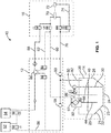
- FIG. 1 A schematic layout of the ink system 10 is shown in FIG. 1 .
- components of the system may be grouped as a valve module 12, a core module 14, and a print head 16.
- the ink system 10 includes fluid tank 20, a first fluid conduit 30 disposed in the fluid tank 20, and a second fluid conduit 40 disposed in the tank 20.
- the bottom portion of fluid tank 20 includes a generally conically shaped side wall 22.
- the side wall 22 slopes inwardly from a top portion 21 to the bottom portion 23.
- a bottom surface 24 is disposed adjacent the bottom portion 23 of the side wall 22.
- First conduit 30 and second conduit 40 are used to remove ink from the tank 20 and recirculate it back to the tank 20, depending on the operating condition of the system 10.
- the fluid tank 20 is especially suitable for use with a pigment based ink composition.
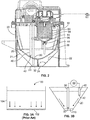
- FIG. 2 is a sectional view of an embodiment of the fluid tank 20.
- fluid tank 20 is about 1 L in volume.
- the top portion of fluid tank 20 may include side walls 25 and 26.
- the bottom portion of fluid tank 20 includes a generally conically shaped side wall 22 that slopes inwardly from a top portion 21 (connected to side walls 25 and 26) to the bottom portion 23 adjacent bottom surface 24.
- the bottom surface 24 is circular in shape and about 25 mm in diameter.
- side walls 25 and 26 along with front and back walls may provide a generally square frame (when viewed from the top), and walls 25 and 26 are about 150 mm apart at the farthest point.
- Conically shaped side wall 22 may slope to the bottom surface 24 at an angle ⁇ with respect to the bottom surface 24.
- the angle ⁇ is preferably between 105° and 165 °, more preferably between 120° and 150°.
- First conduit 30 includes an opening 32 adjacent to and above the bottom surface 24 of the fluid tank 20. Opening 32 may be positioned between about 25.4 and 50.8 mm (1 and 2 inches) from the bottom surface 24. Opening 32 is preferably located between less than about 25.4 mm (1 inch) more preferably less than about 6.35 mm (0.25 inches) from the bottom surface 24.
- the second fluid conduit 40 includes an opening 42 disposed in the fluid tank 20 at a location above the opening 32 of the first fluid conduit 30.
- the ink system 10 also includes an ink pump 50 in fluid communication with the first fluid conduit 30.
- the ink pump 50 may be any suitable fluid pump. Examples suitable pumps include a piston-type pump, a diaphragm pump, a vane pump and a gear pump. In general, the pump can be any device that generates a pressure difference between its inlet and outlet ports. The pump can be powered electrically, hydraulically, pneumatically or mechanically. The ink pump 50 is operable to convey fluid in either direction from fluid conduit 30.
- the system 10 may include an ink source 52 and a solvent or make-up source 54.
- the ink source 52 and solvent or make-up source 54 may be provided in bottles, cartridges, or any other suitable containers. Flow of fluid out of ink source 52 and make-up source 54 are controlled by valves Vi and Vm, respectively. Ink and/or make-up fluid may be provided to fluid tank 20 via supply line 56 and transfer pump 58.
- the ink source 52 provides a volume of ink. If the ink source 52 contains a pigmented ink composition, the container of ink source 52 should be thoroughly agitated to suspend the pigment particles.
- solvent from solvent source 54 may also be periodically provided to fluid tank 20 to replace solvent loss through evaporation during printing.
- An ink supply line 60 is in fluid communication with the pump 50, thus providing ink to nozzle 70 in print head 16.
- a valve VF operates to control flow of the ink to the nozzle 70.
- Ink is supplied to print head 16 from tank 20 via conduit 30, pump 50, and ink supply line 60.
- gutter 72 collects unused ink droplets and recirculates them back via gutter line 74, return line 76, gutter pump 80, and line 82 back to fluid tank 20.
- Valve VG controls the flow of fluid via gutter line 74.
- make-up fluid may be supplied to nozzle 70 via flush line 88 and flush pump 86, as will be described in further detail below.
- Flush pump 86 may be a double-chambered diaphragm pump to provide for both solvent flow through flush line 88 and ink flow through line 62.
- the various valves are preferably media-separated valves, such as commercially available media separated valves that are separated with an elastomer.
- the ink system 10 preferably includes a filter module 90 in fluid communication with the pump 50.
- the filter module 90 includes a housing 92 and filter media 94 disposed in the housing 92.
- a fluid inlet 96 is disposed in a side portion of the housing 92.
- a first fluid outlet 97 is disposed in a top portion of the housing 92, with the filter media 94 disposed between the fluid inlet 96 and the fluid outlet 97.
- a second fluid outlet 98 is disposed in a bottom portion of the housing 92 and connects to conduit 44.
- the area 93 of the filter 90 above the filter outlet 98 is preferably conically shaped to help prevent settling of pigment within the filter module 90.
- outlet 98 serves a mixing function by providing continuous flow of the ink composition to help keep the pigment suspended in fluid tank 20.
- FIG. 3A A prior art ink system 100 is shown in FIG. 3A .
- pigment 102 settles in the bottom of the tank 104 and is very difficult to re-suspend.
- FIG. 3B the pigment tends to settle in a small area 110 at the bottom of the tank 20, due to the conical shape of the tank 20.
- the system 10 includes various mixing and purging procedures to ensure that the pigment is properly dispersed in the fluid.
- the mixing procedure may occur on startup and/or at regular intervals (e.g. once a day).
- suspension of the pigment is accomplished by conveying the ink composition into the second fluid conduit 40 and then back out of the first fluid conduit 30 and into the fluid tank 20 for a first period of time.
- the pigment tends to settle in the central area 110 at the bottom of the tank.
- the fluid flow "blasts" the settled pigment at the bottom of the tank back into dispersion in the fluid.
- This first period of time is preferably at least 30 s, more preferably about 1 min.
- the period of time is preferably less than 5 minutes.
- the flow rate of the fluid through the pump 50 and conduits 30 and 40 is preferably about 1 to 2 L/min.
- valve VT controls the flow of fluid through conduit 40. During the mixing procedure, valve VT is open to allow flow to and from conduit 40.
- valve VT is closed so the fluid flows from ink pump 50 into filter module 90 and then to ink supply line 60. It has been found that the two step mixing procedure describe above works extremely well to thoroughly mix the ink composition in a short period of time (about 6 minutes total), in comparison to prior art mixing systems.
- the system 10 may also include filter purge process to remove settled pigment out of filter module 90, including housing 92 and filter media 94.
- filter purge process to remove settled pigment out of filter module 90, including housing 92 and filter media 94.
- ink pump 50 is used to convey fluid from the fluid tank 20 into conduit 30 to filter module 90 and then out of outlet 98 through conduit 44.
- the generally conical shape of area 93 helps to ensure that sediment is able to be flushed out of outlet 98 back into the fluid tank 20.
- the filter purge process may take about 1 minute.
- the mixing procedure may also include a procedure for purging the ink supply line 60 and the return line 62.
- purging is meant that the lines are flushed with mixed ink composition from tank 20 to help remove any settled pigment in the lines.
- the ink composition is transferred via conduit 30 and ink pump 50 to ink supply line 60, bypassing the nozzle 70 with valve VF closed, and then back through return line 62 via transfer pump 58 back into line 82. This cycle is done for a sufficient period of time to essentially flush the lines 60 and 62 of settled pigment.
- the ink system 10 is configured to include features to minimize or prevent the settling of pigment within the lines or other components.
- ink flows from the fluid tank 20, through feed line 60, and through open valve VF to the nozzle 70.
- valve VF is closed.
- the system 10 may perform a flush cycle at certain periods of time, such as shutdown, startup, or as part of a regular cleaning procedure.
- the print head 16 may be flushed with solvent to remove ink from the nozzle(s) 70 in print head 16.
- valve VL is used to change from ink flow to solvent flow to print head 16.
- solvent flows through line 88 from flush pump 86 through valve VL to nozzle 70 and gutter 72.
- Gutter pump 80 pulls solvent and air into line 76 from gutter line 74, and thence back to ink tank 20 via line 82. This procedure removes nearly all the ink from the nozzle(s) in print head 70.
- the present invention further provides an ink jet printer that includes the ink system described above.
- the printer can be of any type, such as a continuous ink jet printer or a drop-on-demand ink jet printer.
- the ink system 10 is especially suitable for use with a 1000-series continuous ink jet system available from Videojet Technologies Inc. (Wood Dale, IL).
- the operation of the various valves and pumps of the system 10 may provided by a standard controller, which may be provided as an integrated component or a separate computer. Such controllers are well known in the art.
Landscapes
- Ink Jet (AREA)
Claims (15)
- Tintensystem (10) eines Tintenstrahldruckers, umfassend:
einen Flüssigkeitsbehälter (20), umfassend:eine im Wesentlichen konisch geformte Seitenwand (22), wobei die Seitenwand von einem Oberteil (21) zu einem Unterteil (23) nach innen geneigt ist; undeine Bodenfläche (24), die benachbart zu dem Unterteil (23) der Seitenwand angeordnet ist;eine Tintenzusammensetzung, umfassend ein Pigment, die in dem Flüssigkeitsbehälter angeordnet ist;eine erste Flüssigkeitsleitung (30), die in dem Flüssigkeitsbehälter angeordnet ist und eine Öffnung (32) benachbart zu und über der Bodenfläche (24) des Flüssigkeitsbehälters umfasst;eine zweite Flüssigkeitsleitung (40), die in dem Flüssigkeitsbehälter angeordnet ist und eine Öffnung (42) an einer Stelle über der Öffnung (32) der ersten Flüssigkeitsleitung (30) umfasst;eine Pumpe (50) in Fluidverbindung mit der ersten Flüssigkeitsleitung (30) und der zweiten Flüssigkeitsleitung (40), wobei die Pumpe betriebsfähig ist, um die Tintenzusammensetzung in einer beliebigen Richtung durch die erste Flüssigkeitsleitung (30) und die zweite Flüssigkeitsleitung (40) zu befördern;eine Tintenversorgungsleitung (60) in Fluidverbindung mit der Pumpe (50);einen Druckkopf (16) in Fluidverbindung mit der Tintenversorgungsleitung (60); undeine Rückleitung (76) in Fluidverbindung zwischen dem Druckkopf (16) und dem Flüssigkeitsbehälter (20). - Tintensystem nach Anspruch 1, ferner umfassend:
eine Tintenquelle (52) in Fluidverbindung mit dem Flüssigkeitsbehälter (20), wobei die Tintenquelle eine pigmentierte Tintenzusammensetzung umfasst, die in einer Patrone bereitgestellt ist. - Tintensystem nach Anspruch 1, wobei:die Rückleitung (76) die Zirkulation einer Flüssigkeit von der Versorgungsleitung (60) zu dem Flüssigkeitsbehälter (20) erlaubt; und/oderdie Öffnung (32) der ersten Flüssigkeitsleitung (30) weniger als 6,35 mm (0,25 Zoll) von der Bodenfläche (24) entfernt angeordnet ist.
- Tintensystem nach Anspruch 1, ferner umfassend ein Filtermodul (90) in Fluidverbindung mit der Pumpe (50), wobei das Filtermodul (90) Folgendes umfasst:ein Gehäuse (92);ein Filtermedium (94), das in dem Gehäuse angeordnet ist;einen Flüssigkeitseinlass (96), der in dem Gehäuse angeordnet ist; undeinen Flüssigkeitsauslass (98), der in einem Unterteil des Gehäuses angeordnet ist, wobei das Gehäuse einen im Allgemeinen konisch geformten Abschnitt (93) benachbart zu dem Flüssigkeitsauslass (98) beinhaltet.
- Tintensystem nach Anspruch 1, ferner umfassend ein Ventil, das den Fluss von Flüssigkeit von der Tintenversorgungsleitung (60) zu einer Düse (70) in dem Druckkopf (16) steuert, wobei das Ventil ein mediengetrenntes Ventil ist.
- Verfahren des Betreibens eines Tintenstrahldruckers, umfassend:
Bereitstellen eines Tintensystems (10), umfassend:
einen Flüssigkeitsbehälter (20), umfassend:eine im Wesentlichen konisch geformte Seitenwand (22), wobei die Seitenwand von einem Oberteil (21) zu einem Unterteil (23) nach innen geneigt ist; undeine Bodenfläche (24), die benachbart zu dem Unterteil (23) der Seitenwand angeordnet ist;eine Tintenzusammensetzung, umfassend ein Pigment, die in dem Flüssigkeitsbehälter (20) angeordnet ist;eine erste Flüssigkeitsleitung (30), die in dem Flüssigkeitsbehälter angeordnet ist und eine Öffnung (32) benachbart zu und über der Bodenfläche (24) des Flüssigkeitsbehälters umfasst; undeine zweite Flüssigkeitsleitung (40), die in dem Flüssigkeitsbehälter angeordnet ist und eine Öffnung (42) an einer Stelle über der Öffnung (32) der ersten Flüssigkeitsleitung (30) umfasst; undDurchführen eines Mischvorgangs, umfassend:Befördern der Tintenzusammensetzung in die zweite Flüssigkeitsleitung (40) und aus der ersten Flüssigkeitsleitung (30) in den Flüssigkeitsbehälter (20) für einen ersten Zeitraum undUmkehren des Flusses der Tintenzusammensetzung, um die Tintenzusammensetzung in die erste Flüssigkeitsleitung (30) und aus der zweiten Flüssigkeitsleitung (40) in den Flüssigkeitsbehälter für einen zweiten Zeitraum zu befördern, wodurch die Tintenzusammensetzung vermischt wird. - Verfahren nach Anspruch 6, wobei der Mischvorgang in regelmäßigen Abständen durchgeführt wird, optional
in einem täglichen Abstand. - Verfahren nach Anspruch 6, wobei:der zweite Zeitraum mindestens 5 min beträgt; oderdas System ein Filtermodul (90) umfasst, das in Fluidverbindung mit der ersten Flüssigkeitsleitung (30) angeordnet ist, wobei das Verfahren ferner das Befördern der Tintenzusammensetzung von der ersten Flüssigkeitsleitung (30) in das Filtermodul (90) umfasst.
- Verfahren nach Anspruch 6, wobei das System ein Filtermodul (90) umfasst, das in Fluidverbindung mit der ersten Flüssigkeitsleitung (30) angeordnet ist und
wobei eine dritte Leitung (44) eine Fluidverbindung zwischen dem Filtermodul (90) und dem Flüssigkeitsbehälter (20) bereitstellt, wobei das Verfahren ferner das Befördern der Tintenzusammensetzung von der ersten Flüssigkeitsleitung (30) in das Filtermodul (90) und
das Befördern von Flüssigkeit von der ersten Flüssigkeitsleitung (30) durch das Filtermodul (90) und von dem Filtermodul zurück zu dem Flüssigkeitsbehälter (20) umfasst, um das Filtermodul (90) zu reinigen. - Verfahren nach Anspruch 9, wobei das Filtermodul einen im Allgemeinen konisch geformten Innenabschnitt (93) benachbart zu einem Flüssigkeitsauslass (98) in Fluidverbindung mit dem Flüssigkeitsbehälter (20) beinhaltet.
- Verfahren nach Anspruch 6, wobei das System ferner Folgendes umfasst:eine Tintenversorgungsleitung (60) in Fluidverbindung mit dem Flüssigkeitsbehälter (20);einen Druckkopf (16) in Fluidverbindung mit der Tintenversorgungsleitung (60), wobei der Druckkopf eine Düse (70) umfasst;ein Ventil, das den Fluss von Flüssigkeit von der Tintenversorgungsleitung (60) zu der Düse (70) steuert; undeine Rückleitung (62) in Fluidverbindung zwischen dem Druckkopf (16) und dem Flüssigkeitsbehälter (20),wobei das Verfahren ferner Folgendes umfasst:Schließen des Ventils, um einen Fluss von Tinte zu dem Druckkopf zu verhindern; undBereitstellen eines Flusses der Tintenzusammensetzung durch die Tintenversorgungsleitung (60), die Rückleitung (62) und zurück zu dem Flüssigkeitsbehälter (20), wodurch die Tintenversorgungsleitung (60) und die Rückleitung (62) gereinigt werden.
- Verfahren nach Anspruch 6, wobei das System ferner Folgendes umfasst:eine Tintenversorgungsleitung in Fluidverbindung mit dem Flüssigkeitsbehälter;einen Druckkopf in Fluidverbindung mit der Tintenversorgungsleitung;ein Ventil, das den Fluss von Flüssigkeit von der Tintenversorgungsleitung zu dem Druckkopf steuert; undeine Rückleitung in Fluidverbindung zwischen dem Druckkopf und dem Flüssigkeitsbehälter,wobei das Verfahren ferner Folgendes umfasst:Betreiben des Ventils, um den Druckkopf mit Tinte zu versorgen, wenn das System in einem Druckmodus ist;Betreiben des Ventils, um einen Tintenfluss zu dem Druckkopf zu verhindern, wenn das System nicht in einem Druckmodus ist; undBereitstellen eines Flusses von Lösungsmittel durch die Tintenversorgungsleitung und die Rückleitung, wenn der Drucker in einem Spülmodus ist.
- Verfahren nach Anspruch 6, ferner umfassend:Bereitstellen einer Tintenquelle (52), umfassend ein Tintenvolumen;Bereitstellen einer Lösungsmittelquelle (54), umfassend ein Lösungsmittelvolumen;Übermitteln von im Wesentlichen dem gesamten Tintenvolumen an den Flüssigkeitsbehälter durch eine Versorgungsleitung (56); undÜbermitteln eines Abschnitts des Lösungsmittelvolumens durch die Versorgungsleitung (56), um die Versorgungsleitung durchzuspülen.
- Verfahren nach Anspruch 13, wobei die Tintenquelle ein Volumen von pigmentierter Tinte in einer Patrone umfasst.
- Verfahren nach einem der Ansprüche 6 bis 14, wobei der erste Zeitraum mindestens 30 s beträgt und der zweite Zeitraum mindestens 1 min beträgt.
Priority Applications (1)
| Application Number | Priority Date | Filing Date | Title |
|---|---|---|---|
| EP19177840.6A EP3575091A1 (de) | 2011-01-31 | 2012-01-23 | Tintenmischsystem |
Applications Claiming Priority (2)
| Application Number | Priority Date | Filing Date | Title |
|---|---|---|---|
| US13/017,195 US8371684B2 (en) | 2011-01-31 | 2011-01-31 | Ink mixing system |
| PCT/US2012/022187 WO2012106134A1 (en) | 2011-01-31 | 2012-01-23 | Ink mixing system |
Related Child Applications (1)
| Application Number | Title | Priority Date | Filing Date |
|---|---|---|---|
| EP19177840.6A Division EP3575091A1 (de) | 2011-01-31 | 2012-01-23 | Tintenmischsystem |
Publications (2)
| Publication Number | Publication Date |
|---|---|
| EP2670601A1 EP2670601A1 (de) | 2013-12-11 |
| EP2670601B1 true EP2670601B1 (de) | 2019-06-05 |
Family
ID=45562474
Family Applications (2)
| Application Number | Title | Priority Date | Filing Date |
|---|---|---|---|
| EP19177840.6A Pending EP3575091A1 (de) | 2011-01-31 | 2012-01-23 | Tintenmischsystem |
| EP12702376.0A Active EP2670601B1 (de) | 2011-01-31 | 2012-01-23 | Tintenmischsystem |
Family Applications Before (1)
| Application Number | Title | Priority Date | Filing Date |
|---|---|---|---|
| EP19177840.6A Pending EP3575091A1 (de) | 2011-01-31 | 2012-01-23 | Tintenmischsystem |
Country Status (4)
| Country | Link |
|---|---|
| US (2) | US8371684B2 (de) |
| EP (2) | EP3575091A1 (de) |
| CN (1) | CN103476592B (de) |
| WO (1) | WO2012106134A1 (de) |
Cited By (1)
| Publication number | Priority date | Publication date | Assignee | Title |
|---|---|---|---|---|
| IT202200004577A1 (it) * | 2022-03-10 | 2023-09-10 | Zanasi S R L | Un sistema di circolazione dell’inchiostro per una stampante a getto d'inchiostro |
Families Citing this family (17)
| Publication number | Priority date | Publication date | Assignee | Title |
|---|---|---|---|---|
| CN106103609B (zh) * | 2014-03-28 | 2020-11-03 | 马姆杰特科技有限公司 | 用于改善印刷头寿命的油墨配制品 |
| US9272523B2 (en) | 2014-04-02 | 2016-03-01 | Memjet Technology Ltd. | Printer configured for optimized printing |
| CN104029492A (zh) * | 2014-06-05 | 2014-09-10 | 苏州铉动三维空间科技有限公司 | 一种打印机用墨盒 |
| AU2015271713B2 (en) * | 2014-06-05 | 2018-04-19 | Videojet Technologies Inc. | A self-sealing filter module for inkjet printing |
| FR3026050A1 (fr) | 2014-09-18 | 2016-03-25 | Markem Imaje Holding | Circuit d'encre pour encres pigmentaires |
| CN107914471B (zh) | 2015-05-13 | 2019-09-20 | 佳能株式会社 | 液容器和安装有液容器的记录装置 |
| JP6756114B2 (ja) * | 2016-02-09 | 2020-09-16 | セイコーエプソン株式会社 | フィルターユニット及び液体噴射装置 |
| JP6853366B2 (ja) * | 2017-04-21 | 2021-03-31 | ヒューレット−パッカード デベロップメント カンパニー エル.ピー.Hewlett‐Packard Development Company, L.P. | プリンタにおける流体の再循環 |
| US10926546B2 (en) | 2017-04-24 | 2021-02-23 | Hewlett-Packard Development Company, L.P. | Deformable fluid supply |
| GB2566740B (en) * | 2017-09-26 | 2021-07-14 | Linx Printing Tech | Pigment dispersal in an ink jet printer |
| EP3501835B1 (de) * | 2017-12-20 | 2024-02-07 | Canon Production Printing Holding B.V. | Tintenreservoir zur bereitstellung von tinte an einen druckkopf eines tintenstrahldruckers |
| US10807372B2 (en) | 2018-01-29 | 2020-10-20 | Ricoh Company, Ltd. | Liquid droplet discharging unit, liquid droplet forming device, and stirring device |
| CN208088530U (zh) | 2018-02-10 | 2018-11-13 | 苏州兹安材料科技有限公司 | 具有立体结构的防水透湿布及生产线与墙体结构 |
| GB2575986A (en) | 2018-07-30 | 2020-02-05 | Domino Uk Ltd | Solvent supply tube arrangement |
| CN113316519B (zh) * | 2019-01-30 | 2022-10-14 | 惠普发展公司,有限责任合伙企业 | 传输和混合用于打印的墨的方法和系统 |
| GB201919228D0 (en) | 2019-12-23 | 2020-02-05 | Videojet Technologies Inc | Method of operating a printhead |
| CN112706527B (zh) * | 2020-12-25 | 2022-05-17 | 镭德杰标识科技武汉有限公司 | 一种供墨系统 |
Citations (1)
| Publication number | Priority date | Publication date | Assignee | Title |
|---|---|---|---|---|
| EP1235689B1 (de) * | 1999-10-29 | 2004-06-30 | Videojet Technologies Inc. | Umlaufsystem und verfahren zum mischen von tintenstrahldrucktinte |
Family Cites Families (25)
| Publication number | Priority date | Publication date | Assignee | Title |
|---|---|---|---|---|
| FR2652540B1 (fr) | 1989-10-02 | 1995-06-02 | Imaje Sa | Circuit d'encre notamment destine a la mise en pression d'une encre a pigments pour imprimante a jet d'encre. |
| US5473350A (en) | 1992-08-06 | 1995-12-05 | Scitex Digital Printing, Inc. | System and method for maintaining ink concentration in a system |
| US5742308A (en) | 1994-03-30 | 1998-04-21 | Hewlett-Packard Company | Ink jet printer cartridge refilling method and apparatus |
| JP3167598B2 (ja) | 1995-10-13 | 2001-05-21 | キヤノン株式会社 | インクタンクおよびインクジェット記録装置 |
| CN1123448C (zh) * | 1997-07-01 | 2003-10-08 | 录象射流系统国际有限公司 | 用于喷墨打印头的就地清洁系统 |
| JP3846083B2 (ja) * | 1998-02-06 | 2006-11-15 | ブラザー工業株式会社 | インクジェット記録装置 |
| JP2000071477A (ja) * | 1998-06-17 | 2000-03-07 | Canon Inc | インク供給装置およびインクジェット記録ヘッド |
| EP1083053A1 (de) | 1999-09-09 | 2001-03-14 | De La Rue Giori S.A. | Tintenstrahldruckvorrichtung für Tinten mit hoher Pigmentkonzentration und diese Vorrichtung gebrauchendes Tintenstrahldruckverfahren |
| EP1083054A1 (de) | 1999-09-09 | 2001-03-14 | De La Rue Giori S.A. | Anordnung eines kontinuierlichen Tintenstrahldruckers |
| JP3852256B2 (ja) | 1999-11-10 | 2006-11-29 | 富士ゼロックス株式会社 | インクジェット記録装置 |
| JP3697213B2 (ja) * | 2001-02-09 | 2005-09-21 | キヤノン株式会社 | 液体収納容器、および液体の撹拌方法 |
| JP2003291373A (ja) | 2002-04-05 | 2003-10-14 | Hitachi Printing Solutions Ltd | インクジェット記録装置 |
| AU2003264950B2 (en) * | 2002-09-30 | 2008-07-24 | Canon Kabushiki Kaisha | Liquid supply system, fluid communicating structure, ink supply system, and inkjet recording head utilizing the fluid communicating structure |
| JP4191972B2 (ja) | 2002-10-04 | 2008-12-03 | 株式会社リコー | インク液混合装置、インク液製造装置、製造方法、洗浄方法及び該製造方法で製造されたインク、及びそれを収納したインクカートリッジ、インクジェット装置、画像形成方法並びに画像形成物 |
| US7442180B2 (en) * | 2003-06-10 | 2008-10-28 | Hewlett-Packard Development Company, L.P. | Apparatus and methods for administering bioactive compositions |
| US7819847B2 (en) | 2003-06-10 | 2010-10-26 | Hewlett-Packard Development Company, L.P. | System and methods for administering bioactive compositions |
| JP2005067122A (ja) * | 2003-08-27 | 2005-03-17 | Fuji Photo Film Co Ltd | インクジェット記録装置 |
| JP2006192638A (ja) | 2005-01-12 | 2006-07-27 | Fuji Photo Film Co Ltd | インクジェット記録装置 |
| JP4539517B2 (ja) * | 2005-09-29 | 2010-09-08 | ブラザー工業株式会社 | インクカートリッジ |
| US7635180B2 (en) | 2005-09-29 | 2009-12-22 | Brother Kogyo Kabushiki Kaisha | Ink cartridge |
| GB0720131D0 (en) * | 2007-10-12 | 2007-11-28 | Videojet Technologies Inc | Ink jet printing |
| GB0720290D0 (en) * | 2007-10-12 | 2007-11-28 | Videojet Technologies Inc | Ink jet printer |
| JP2009285837A (ja) * | 2008-05-27 | 2009-12-10 | Dainippon Screen Mfg Co Ltd | 印刷装置、インク循環方法およびインク初期導入方法 |
| JP5371678B2 (ja) * | 2009-10-13 | 2013-12-18 | 株式会社ミマキエンジニアリング | 液体循環システム及びインクジェットプリンタ |
| DE102010061001B4 (de) * | 2010-12-03 | 2013-07-04 | OCé PRINTING SYSTEMS GMBH | Tintendrucker mit einem Tintenzwischenbehälter und einem Strömungsrichtungsgeber zum Durchmischen der Tinte |
-
2011
- 2011-01-31 US US13/017,195 patent/US8371684B2/en active Active
-
2012
- 2012-01-23 EP EP19177840.6A patent/EP3575091A1/de active Pending
- 2012-01-23 CN CN201280007171.6A patent/CN103476592B/zh active Active
- 2012-01-23 EP EP12702376.0A patent/EP2670601B1/de active Active
- 2012-01-23 WO PCT/US2012/022187 patent/WO2012106134A1/en not_active Ceased
- 2012-12-11 US US13/710,875 patent/US9039155B2/en active Active
Patent Citations (1)
| Publication number | Priority date | Publication date | Assignee | Title |
|---|---|---|---|---|
| EP1235689B1 (de) * | 1999-10-29 | 2004-06-30 | Videojet Technologies Inc. | Umlaufsystem und verfahren zum mischen von tintenstrahldrucktinte |
Cited By (2)
| Publication number | Priority date | Publication date | Assignee | Title |
|---|---|---|---|---|
| IT202200004577A1 (it) * | 2022-03-10 | 2023-09-10 | Zanasi S R L | Un sistema di circolazione dell’inchiostro per una stampante a getto d'inchiostro |
| EP4242001A1 (de) * | 2022-03-10 | 2023-09-13 | Zanasi S.r.l. | Tintenrückführungssystem für einen tintenstrahldrucker |
Also Published As
| Publication number | Publication date |
|---|---|
| US20140002551A1 (en) | 2014-01-02 |
| US8371684B2 (en) | 2013-02-12 |
| WO2012106134A1 (en) | 2012-08-09 |
| CN103476592A (zh) | 2013-12-25 |
| CN103476592B (zh) | 2016-08-17 |
| EP2670601A1 (de) | 2013-12-11 |
| US20120194619A1 (en) | 2012-08-02 |
| EP3575091A1 (de) | 2019-12-04 |
| US9039155B2 (en) | 2015-05-26 |
Similar Documents
| Publication | Publication Date | Title |
|---|---|---|
| EP2670601B1 (de) | Tintenmischsystem | |
| CN101659147B (zh) | 喷墨记录装置 | |
| TW201420366A (zh) | 組構爲用於有效率氣泡移出之印表機 | |
| CN104890369B (zh) | 液体喷射装置及其控制方法 | |
| CN106604824B (zh) | 用于喷墨打印的自密封过滤模块 | |
| WO2009157139A1 (ja) | 印刷装置 | |
| KR20120069774A (ko) | 액체 순환 시스템 | |
| CN101830111A (zh) | 液体喷射装置 | |
| JP2007536117A (ja) | インクジェット印刷ヘッドのシャットダウン方法 | |
| CN109130523B (zh) | 一种墨水循环方法及其系统 | |
| KR20190079823A (ko) | 잉크젯 프린팅 장치 | |
| JP4746305B2 (ja) | ヘッドモジュール | |
| CN103072379A (zh) | 液体供给装置和喷墨记录装置 | |
| CN108472962B (zh) | 用于喷墨打印机的供应系统 | |
| JP2007275822A (ja) | 液滴吐出装置ならびにそれの運転方法 | |
| JP2011110850A (ja) | 液体循環システム | |
| JP3631085B2 (ja) | インクジェットプリンタの液体循環装置 | |
| JP6069965B2 (ja) | 液体吐出装置 | |
| US10300719B2 (en) | Rotating a printhead relative to vertical | |
| WO2015150148A1 (en) | Printer configured for optimized priming | |
| JP7013972B2 (ja) | 液体を吐出する装置 | |
| CN114728525A (zh) | 用于卡片处理系统的采用无罐再循环的按需输墨系统和方法 | |
| JP2006247450A (ja) | 液体吐出装置及びパターニング装置 | |
| CN110281656A (zh) | 一种用于喷墨打印机的循环墨路系统及墨路循环方法 | |
| CN219947663U (zh) | 一种墨水供应系统及打印装置 |
Legal Events
| Date | Code | Title | Description |
|---|---|---|---|
| PUAI | Public reference made under article 153(3) epc to a published international application that has entered the european phase |
Free format text: ORIGINAL CODE: 0009012 |
|
| 17P | Request for examination filed |
Effective date: 20130701 |
|
| AK | Designated contracting states |
Kind code of ref document: A1 Designated state(s): AL AT BE BG CH CY CZ DE DK EE ES FI FR GB GR HR HU IE IS IT LI LT LU LV MC MK MT NL NO PL PT RO RS SE SI SK SM TR |
|
| DAX | Request for extension of the european patent (deleted) | ||
| 17Q | First examination report despatched |
Effective date: 20160216 |
|
| STAA | Information on the status of an ep patent application or granted ep patent |
Free format text: STATUS: EXAMINATION IS IN PROGRESS |
|
| GRAP | Despatch of communication of intention to grant a patent |
Free format text: ORIGINAL CODE: EPIDOSNIGR1 |
|
| STAA | Information on the status of an ep patent application or granted ep patent |
Free format text: STATUS: GRANT OF PATENT IS INTENDED |
|
| INTG | Intention to grant announced |
Effective date: 20181220 |
|
| GRAS | Grant fee paid |
Free format text: ORIGINAL CODE: EPIDOSNIGR3 |
|
| GRAA | (expected) grant |
Free format text: ORIGINAL CODE: 0009210 |
|
| STAA | Information on the status of an ep patent application or granted ep patent |
Free format text: STATUS: THE PATENT HAS BEEN GRANTED |
|
| AK | Designated contracting states |
Kind code of ref document: B1 Designated state(s): AL AT BE BG CH CY CZ DE DK EE ES FI FR GB GR HR HU IE IS IT LI LT LU LV MC MK MT NL NO PL PT RO RS SE SI SK SM TR |
|
| REG | Reference to a national code |
Ref country code: GB Ref legal event code: FG4D |
|
| REG | Reference to a national code |
Ref country code: CH Ref legal event code: EP |
|
| REG | Reference to a national code |
Ref country code: AT Ref legal event code: REF Ref document number: 1139588 Country of ref document: AT Kind code of ref document: T Effective date: 20190615 |
|
| REG | Reference to a national code |
Ref country code: IE Ref legal event code: FG4D |
|
| REG | Reference to a national code |
Ref country code: DE Ref legal event code: R096 Ref document number: 602012060688 Country of ref document: DE |
|
| REG | Reference to a national code |
Ref country code: NL Ref legal event code: MP Effective date: 20190605 |
|
| REG | Reference to a national code |
Ref country code: LT Ref legal event code: MG4D |
|
| PG25 | Lapsed in a contracting state [announced via postgrant information from national office to epo] |
Ref country code: SE Free format text: LAPSE BECAUSE OF FAILURE TO SUBMIT A TRANSLATION OF THE DESCRIPTION OR TO PAY THE FEE WITHIN THE PRESCRIBED TIME-LIMIT Effective date: 20190605 Ref country code: NO Free format text: LAPSE BECAUSE OF FAILURE TO SUBMIT A TRANSLATION OF THE DESCRIPTION OR TO PAY THE FEE WITHIN THE PRESCRIBED TIME-LIMIT Effective date: 20190905 Ref country code: AL Free format text: LAPSE BECAUSE OF FAILURE TO SUBMIT A TRANSLATION OF THE DESCRIPTION OR TO PAY THE FEE WITHIN THE PRESCRIBED TIME-LIMIT Effective date: 20190605 Ref country code: FI Free format text: LAPSE BECAUSE OF FAILURE TO SUBMIT A TRANSLATION OF THE DESCRIPTION OR TO PAY THE FEE WITHIN THE PRESCRIBED TIME-LIMIT Effective date: 20190605 Ref country code: LT Free format text: LAPSE BECAUSE OF FAILURE TO SUBMIT A TRANSLATION OF THE DESCRIPTION OR TO PAY THE FEE WITHIN THE PRESCRIBED TIME-LIMIT Effective date: 20190605 Ref country code: HR Free format text: LAPSE BECAUSE OF FAILURE TO SUBMIT A TRANSLATION OF THE DESCRIPTION OR TO PAY THE FEE WITHIN THE PRESCRIBED TIME-LIMIT Effective date: 20190605 Ref country code: ES Free format text: LAPSE BECAUSE OF FAILURE TO SUBMIT A TRANSLATION OF THE DESCRIPTION OR TO PAY THE FEE WITHIN THE PRESCRIBED TIME-LIMIT Effective date: 20190605 |
|
| PG25 | Lapsed in a contracting state [announced via postgrant information from national office to epo] |
Ref country code: LV Free format text: LAPSE BECAUSE OF FAILURE TO SUBMIT A TRANSLATION OF THE DESCRIPTION OR TO PAY THE FEE WITHIN THE PRESCRIBED TIME-LIMIT Effective date: 20190605 Ref country code: RS Free format text: LAPSE BECAUSE OF FAILURE TO SUBMIT A TRANSLATION OF THE DESCRIPTION OR TO PAY THE FEE WITHIN THE PRESCRIBED TIME-LIMIT Effective date: 20190605 Ref country code: BG Free format text: LAPSE BECAUSE OF FAILURE TO SUBMIT A TRANSLATION OF THE DESCRIPTION OR TO PAY THE FEE WITHIN THE PRESCRIBED TIME-LIMIT Effective date: 20190905 Ref country code: GR Free format text: LAPSE BECAUSE OF FAILURE TO SUBMIT A TRANSLATION OF THE DESCRIPTION OR TO PAY THE FEE WITHIN THE PRESCRIBED TIME-LIMIT Effective date: 20190906 |
|
| REG | Reference to a national code |
Ref country code: AT Ref legal event code: MK05 Ref document number: 1139588 Country of ref document: AT Kind code of ref document: T Effective date: 20190605 |
|
| PG25 | Lapsed in a contracting state [announced via postgrant information from national office to epo] |
Ref country code: CZ Free format text: LAPSE BECAUSE OF FAILURE TO SUBMIT A TRANSLATION OF THE DESCRIPTION OR TO PAY THE FEE WITHIN THE PRESCRIBED TIME-LIMIT Effective date: 20190605 Ref country code: AT Free format text: LAPSE BECAUSE OF FAILURE TO SUBMIT A TRANSLATION OF THE DESCRIPTION OR TO PAY THE FEE WITHIN THE PRESCRIBED TIME-LIMIT Effective date: 20190605 Ref country code: EE Free format text: LAPSE BECAUSE OF FAILURE TO SUBMIT A TRANSLATION OF THE DESCRIPTION OR TO PAY THE FEE WITHIN THE PRESCRIBED TIME-LIMIT Effective date: 20190605 Ref country code: SK Free format text: LAPSE BECAUSE OF FAILURE TO SUBMIT A TRANSLATION OF THE DESCRIPTION OR TO PAY THE FEE WITHIN THE PRESCRIBED TIME-LIMIT Effective date: 20190605 Ref country code: NL Free format text: LAPSE BECAUSE OF FAILURE TO SUBMIT A TRANSLATION OF THE DESCRIPTION OR TO PAY THE FEE WITHIN THE PRESCRIBED TIME-LIMIT Effective date: 20190605 Ref country code: RO Free format text: LAPSE BECAUSE OF FAILURE TO SUBMIT A TRANSLATION OF THE DESCRIPTION OR TO PAY THE FEE WITHIN THE PRESCRIBED TIME-LIMIT Effective date: 20190605 Ref country code: PT Free format text: LAPSE BECAUSE OF FAILURE TO SUBMIT A TRANSLATION OF THE DESCRIPTION OR TO PAY THE FEE WITHIN THE PRESCRIBED TIME-LIMIT Effective date: 20191007 |
|
| PG25 | Lapsed in a contracting state [announced via postgrant information from national office to epo] |
Ref country code: IT Free format text: LAPSE BECAUSE OF FAILURE TO SUBMIT A TRANSLATION OF THE DESCRIPTION OR TO PAY THE FEE WITHIN THE PRESCRIBED TIME-LIMIT Effective date: 20190605 Ref country code: IS Free format text: LAPSE BECAUSE OF FAILURE TO SUBMIT A TRANSLATION OF THE DESCRIPTION OR TO PAY THE FEE WITHIN THE PRESCRIBED TIME-LIMIT Effective date: 20191005 Ref country code: SM Free format text: LAPSE BECAUSE OF FAILURE TO SUBMIT A TRANSLATION OF THE DESCRIPTION OR TO PAY THE FEE WITHIN THE PRESCRIBED TIME-LIMIT Effective date: 20190605 |
|
| REG | Reference to a national code |
Ref country code: DE Ref legal event code: R097 Ref document number: 602012060688 Country of ref document: DE |
|
| PG25 | Lapsed in a contracting state [announced via postgrant information from national office to epo] |
Ref country code: TR Free format text: LAPSE BECAUSE OF FAILURE TO SUBMIT A TRANSLATION OF THE DESCRIPTION OR TO PAY THE FEE WITHIN THE PRESCRIBED TIME-LIMIT Effective date: 20190605 |
|
| PLBE | No opposition filed within time limit |
Free format text: ORIGINAL CODE: 0009261 |
|
| STAA | Information on the status of an ep patent application or granted ep patent |
Free format text: STATUS: NO OPPOSITION FILED WITHIN TIME LIMIT |
|
| PG25 | Lapsed in a contracting state [announced via postgrant information from national office to epo] |
Ref country code: PL Free format text: LAPSE BECAUSE OF FAILURE TO SUBMIT A TRANSLATION OF THE DESCRIPTION OR TO PAY THE FEE WITHIN THE PRESCRIBED TIME-LIMIT Effective date: 20190605 Ref country code: DK Free format text: LAPSE BECAUSE OF FAILURE TO SUBMIT A TRANSLATION OF THE DESCRIPTION OR TO PAY THE FEE WITHIN THE PRESCRIBED TIME-LIMIT Effective date: 20190605 |
|
| 26N | No opposition filed |
Effective date: 20200306 |
|
| PG25 | Lapsed in a contracting state [announced via postgrant information from national office to epo] |
Ref country code: SI Free format text: LAPSE BECAUSE OF FAILURE TO SUBMIT A TRANSLATION OF THE DESCRIPTION OR TO PAY THE FEE WITHIN THE PRESCRIBED TIME-LIMIT Effective date: 20190605 |
|
| PG25 | Lapsed in a contracting state [announced via postgrant information from national office to epo] |
Ref country code: MC Free format text: LAPSE BECAUSE OF FAILURE TO SUBMIT A TRANSLATION OF THE DESCRIPTION OR TO PAY THE FEE WITHIN THE PRESCRIBED TIME-LIMIT Effective date: 20190605 |
|
| REG | Reference to a national code |
Ref country code: CH Ref legal event code: PL |
|
| REG | Reference to a national code |
Ref country code: BE Ref legal event code: MM Effective date: 20200131 |
|
| PG25 | Lapsed in a contracting state [announced via postgrant information from national office to epo] |
Ref country code: LU Free format text: LAPSE BECAUSE OF NON-PAYMENT OF DUE FEES Effective date: 20200123 |
|
| PG25 | Lapsed in a contracting state [announced via postgrant information from national office to epo] |
Ref country code: BE Free format text: LAPSE BECAUSE OF NON-PAYMENT OF DUE FEES Effective date: 20200131 Ref country code: LI Free format text: LAPSE BECAUSE OF NON-PAYMENT OF DUE FEES Effective date: 20200131 Ref country code: CH Free format text: LAPSE BECAUSE OF NON-PAYMENT OF DUE FEES Effective date: 20200131 |
|
| PG25 | Lapsed in a contracting state [announced via postgrant information from national office to epo] |
Ref country code: IE Free format text: LAPSE BECAUSE OF NON-PAYMENT OF DUE FEES Effective date: 20200123 |
|
| PG25 | Lapsed in a contracting state [announced via postgrant information from national office to epo] |
Ref country code: MT Free format text: LAPSE BECAUSE OF FAILURE TO SUBMIT A TRANSLATION OF THE DESCRIPTION OR TO PAY THE FEE WITHIN THE PRESCRIBED TIME-LIMIT Effective date: 20190605 Ref country code: CY Free format text: LAPSE BECAUSE OF FAILURE TO SUBMIT A TRANSLATION OF THE DESCRIPTION OR TO PAY THE FEE WITHIN THE PRESCRIBED TIME-LIMIT Effective date: 20190605 |
|
| PG25 | Lapsed in a contracting state [announced via postgrant information from national office to epo] |
Ref country code: MK Free format text: LAPSE BECAUSE OF FAILURE TO SUBMIT A TRANSLATION OF THE DESCRIPTION OR TO PAY THE FEE WITHIN THE PRESCRIBED TIME-LIMIT Effective date: 20190605 |
|
| P01 | Opt-out of the competence of the unified patent court (upc) registered |
Effective date: 20230530 |
|
| PGFP | Annual fee paid to national office [announced via postgrant information from national office to epo] |
Ref country code: GB Payment date: 20260123 Year of fee payment: 15 |
|
| PGFP | Annual fee paid to national office [announced via postgrant information from national office to epo] |
Ref country code: DE Payment date: 20260121 Year of fee payment: 15 |
|
| PGFP | Annual fee paid to national office [announced via postgrant information from national office to epo] |
Ref country code: FR Payment date: 20260123 Year of fee payment: 15 |