EP2671004B1 - Hockdruck-dichtungsring - Google Patents
Hockdruck-dichtungsring Download PDFInfo
- Publication number
- EP2671004B1 EP2671004B1 EP12742478.6A EP12742478A EP2671004B1 EP 2671004 B1 EP2671004 B1 EP 2671004B1 EP 12742478 A EP12742478 A EP 12742478A EP 2671004 B1 EP2671004 B1 EP 2671004B1
- Authority
- EP
- European Patent Office
- Prior art keywords
- sealing
- piston
- sealing ring
- cylinder
- ring
- Prior art date
- Legal status (The legal status is an assumption and is not a legal conclusion. Google has not performed a legal analysis and makes no representation as to the accuracy of the status listed.)
- Active
Links
Images


Classifications
-
- F—MECHANICAL ENGINEERING; LIGHTING; HEATING; WEAPONS; BLASTING
- F16—ENGINEERING ELEMENTS AND UNITS; GENERAL MEASURES FOR PRODUCING AND MAINTAINING EFFECTIVE FUNCTIONING OF MACHINES OR INSTALLATIONS; THERMAL INSULATION IN GENERAL
- F16J—PISTONS; CYLINDERS; SEALINGS
- F16J15/00—Sealings
- F16J15/46—Sealings with packing ring expanded or pressed into place by fluid pressure, e.g. inflatable packings
- F16J15/48—Sealings with packing ring expanded or pressed into place by fluid pressure, e.g. inflatable packings influenced by the pressure within the member to be sealed
-
- F—MECHANICAL ENGINEERING; LIGHTING; HEATING; WEAPONS; BLASTING
- F16—ENGINEERING ELEMENTS AND UNITS; GENERAL MEASURES FOR PRODUCING AND MAINTAINING EFFECTIVE FUNCTIONING OF MACHINES OR INSTALLATIONS; THERMAL INSULATION IN GENERAL
- F16B—DEVICES FOR FASTENING OR SECURING CONSTRUCTIONAL ELEMENTS OR MACHINE PARTS TOGETHER, e.g. NAILS, BOLTS, CIRCLIPS, CLAMPS, CLIPS OR WEDGES; JOINTS OR JOINTING
- F16B31/00—Screwed connections specially modified in view of tensile load; Break-bolts
- F16B31/04—Screwed connections specially modified in view of tensile load; Break-bolts for maintaining a tensile load
- F16B31/043—Prestressed connections tensioned by means of liquid, grease, rubber, explosive charge, or the like
-
- F—MECHANICAL ENGINEERING; LIGHTING; HEATING; WEAPONS; BLASTING
- F16—ENGINEERING ELEMENTS AND UNITS; GENERAL MEASURES FOR PRODUCING AND MAINTAINING EFFECTIVE FUNCTIONING OF MACHINES OR INSTALLATIONS; THERMAL INSULATION IN GENERAL
- F16J—PISTONS; CYLINDERS; SEALINGS
- F16J15/00—Sealings
- F16J15/02—Sealings between relatively-stationary surfaces
- F16J15/06—Sealings between relatively-stationary surfaces with solid packing compressed between sealing surfaces
- F16J15/061—Sealings between relatively-stationary surfaces with solid packing compressed between sealing surfaces with positioning means
-
- F—MECHANICAL ENGINEERING; LIGHTING; HEATING; WEAPONS; BLASTING
- F16—ENGINEERING ELEMENTS AND UNITS; GENERAL MEASURES FOR PRODUCING AND MAINTAINING EFFECTIVE FUNCTIONING OF MACHINES OR INSTALLATIONS; THERMAL INSULATION IN GENERAL
- F16J—PISTONS; CYLINDERS; SEALINGS
- F16J15/00—Sealings
- F16J15/02—Sealings between relatively-stationary surfaces
- F16J15/06—Sealings between relatively-stationary surfaces with solid packing compressed between sealing surfaces
- F16J15/062—Sealings between relatively-stationary surfaces with solid packing compressed between sealing surfaces characterised by the geometry of the seat
-
- F—MECHANICAL ENGINEERING; LIGHTING; HEATING; WEAPONS; BLASTING
- F16—ENGINEERING ELEMENTS AND UNITS; GENERAL MEASURES FOR PRODUCING AND MAINTAINING EFFECTIVE FUNCTIONING OF MACHINES OR INSTALLATIONS; THERMAL INSULATION IN GENERAL
- F16J—PISTONS; CYLINDERS; SEALINGS
- F16J15/00—Sealings
- F16J15/02—Sealings between relatively-stationary surfaces
- F16J15/06—Sealings between relatively-stationary surfaces with solid packing compressed between sealing surfaces
- F16J15/08—Sealings between relatively-stationary surfaces with solid packing compressed between sealing surfaces with exclusively metal packing
- F16J15/0887—Sealings between relatively-stationary surfaces with solid packing compressed between sealing surfaces with exclusively metal packing the sealing effect being obtained by elastic deformation of the packing
-
- F—MECHANICAL ENGINEERING; LIGHTING; HEATING; WEAPONS; BLASTING
- F16—ENGINEERING ELEMENTS AND UNITS; GENERAL MEASURES FOR PRODUCING AND MAINTAINING EFFECTIVE FUNCTIONING OF MACHINES OR INSTALLATIONS; THERMAL INSULATION IN GENERAL
- F16J—PISTONS; CYLINDERS; SEALINGS
- F16J15/00—Sealings
- F16J15/02—Sealings between relatively-stationary surfaces
- F16J15/06—Sealings between relatively-stationary surfaces with solid packing compressed between sealing surfaces
- F16J15/10—Sealings between relatively-stationary surfaces with solid packing compressed between sealing surfaces with non-metallic packing
- F16J15/104—Sealings between relatively-stationary surfaces with solid packing compressed between sealing surfaces with non-metallic packing characterised by structure
- F16J15/106—Sealings between relatively-stationary surfaces with solid packing compressed between sealing surfaces with non-metallic packing characterised by structure homogeneous
Definitions
- This invention relates to a high-pressure sealing ring.
- the invention particularly relates, but is not limited to, a high-pressure sealing ring suitable for use in seals for hydraulic assemblies.
- the invention can have particular application in hydraulic assemblies (such as hydraulic tensioning jacks or nuts) operating at high pressures and/or temperatures.
- the hydraulic assemblies which may employ the sealing ring included those used in the nuclear, electricity-generating, steam-generating and marine installations.
- DE 102009022334 A1 discloses a seal with an annular sealing body for use in a sealing arrangement and a corresponding sealing arrangement with such a seal.
- the sealing arrangement comprises at least two components forming a housing gap sealed by said sealing.
- the sealing arrangement should be mountable with low mounting forces and pressure forces which might be unsymmetrical and not in the middle of the annular sealing body, as for being mountable by a single screw, like it is often the case in air conditioning systems in the automobile industry.
- the sealing is configured for installation in a mounting space between a first bearing surface of the first component and a second bearing surface of the second component. The two bearing surfaces of the two components extend at an certain installation angle with respect to one another.
- the sealing has a annular sealing body has a cross-section, which is essentially L-shaped with two sealing limbs arranged in a spring-elastic manner with respect to one another. In a non-installed state of the seal the sealing limbs are arranged under a sealing angle, which is larger than the installation angle between the two bearing surfaces of the two components.
- the sealing may comprise additionally a second and / or third deformable sealing element.
- the failure of the sealing rings forming the seals in high-pressure and/or high-temperature hydraulic assemblies is likely to have catastrophic consequences, including the release of radioactive materials, super-heated steam, hazardous liquids or gases (including acids and alkalis), other fluids (including oils and other petrochemical-based products); and/or may result in the mechanical failure of machinery.
- the present invention resides in a sealing ring for use in a hydraulic assembly of the type having a piston slidably received in a cylinder, the sealing ring including: an annular ring body of "substantially L" cross-section, with a leg portion and a foot portion interconnected by an external heel having a curved profile.
- the external heel has a convex profile to form a "rolling" line of sealing contact with a seat in a cylinder or piston to which the ring body is installed.
- the leg has a sealing protrusion intermediate an outer sealing face of the leg, the sealing protrusion having a cylindrical sealing face interposed between a pair of inclined ramp faces, the sealing protrusion and a distal portion of the outer sealing face forming two lines of sealing contact between the ring body and an adjacent cylinder or piston to which the ring body is installed.
- the foot has a toe portion with a relief angle ⁇ in the range of 1° to 5° relative to the central axis of the ring body.
- the sealing ring has a protrusion on an outer sealing face of the leg, or the external heel is, receivable in a recess in an adjacent cylinder or piston to cause the sealing ring to be "locked” in position.
- the hydraulic nut 10 is designed for high-pressure and/or high-temperature applications, including the securing of steam and gas turbines and other nuclear or fossil fuelled power generation plant.
- the hydraulic nut 100 has a tubular hydraulic nut body 1 having a screw-threaded bore 11 therethrough for releasable engagement with a bolt, nut or threaded component (not shown) to be tensioned.
- An annular extension 12 forms the cylinder wall 13 slidably received in the inner annular bore 21 of the body 22 of the piston 2.
- the piston 2 is seated in a spherical washer 4 which bears against an adjacent component (not shown) to be secured by the tensioned bolt, nut or threaded component.
- An optional sacrificial ring (not shown) may be interposed between the body 22 of the piston 2 and the screw-threaded tubular body 31 of the lock ring 3 which is engaged with external screw-threads 14 about the nut body 1.
- a nipple adaptor 8 and closure plug 9 are mounted on the external annular face 15 of the nut body 1 and are connected to ports 16 in the nut body 1, which in turn are connected to the inner annular cavity 17 defined by the annular extension 12 in the nut body 1 and the inner annular bore 21 of the piston 2.
- a nipple 10 in the nipple adaptor 8 connects the hydraulic nut 100 to a source of high-pressure hydraulic fluid (not shown).
- outer and inner sealing rings 5, 6 have the same sectional configuration, the detailed description thereof, with reference to FIGS. 3 to 5 , will be with respect to the inner sealing ring 6.
- the inner sealing ring 6 is of annular configuration, having an annular body 61 in plan view, as illustrated in FIG. 3 .
- the ring body 61 is of "modified-L" cross-section, as illustrated in FIGS. 4 and 5 .
- the ring body 61 has a "leg” 62 and a “foot” 63 with a “valley” 64 on the inner side of the connection there-between.
- the foot 63 has a "toe” 63A in sealing engagement with the cylindrical wall 13 of the annular extension 12 on the nut body 1.
- the "toe” 63A on the foot 63 has a relief angle ⁇ of e.g. 1° - 5° from the central axis of the sealing ring 6 - see FIG. 5
- a curved i.e. convex "heel" 65 externally on the ring body 61, interconnects the leg 62 and the foot 63.
- the external outer sealing face 62A of the leg 62 has an optional secondary sealing protrusion 66 with a (substantially cylindrical) sealing face 67 intermediate inclined ramp faces 68, 69.
- the convex heel 65 allows the sealing ring body 61 to "roll" on the support surface at the corner of the inner annular bore 21 in the piston 2 so that the distal portion of the outer sealing face 62A of the leg 62 can be deflected into sealing contact with the cylindrical side wall of the inner annular bore.
- cylindrical sealing face 67 of the sealing protrusion 66 is also urged into sealing contact with the wall of the inner annular bore 21 in piston 2, so that there are two (2) lines of sealing engagement between the leg 62 of the sealing ring body 61 and the inner annular bore 21 in the piston 2.
- the annular end face 62B on the leg 62 can be engaged by the corresponding abutting face of each component (eg Fig 2 , 22 or 1 ) enable the sealing ring 6 to be fitted in the inner annular bore in piston 2 without the requirement for an insertion ring, as the engagement between the annular end face 62B, and the insertion tool will not adversely effect the sealing engagement between the leg 62 and the inner annular bore 21.
- the curved heel 65 provides a line of "rolling-contact" between the ring body 61 and the corner of the annular inner bore 21 which enables the leg 62 to move into, or out of, sealing contact with the piston 2 as the hydraulic pressure in annular cavity 17 is increased, or decreased, respectively. This ensures that when the hydraulic pressure is increased after the initial increase / decrease cycle, the leg 62 (and sealing protrusion 66) can again make effective sealing contact with the inner annular bore 21 in the piston 2.
- the selection of the material(s) for the manufacture of the sealing ring 6, and the dimensions and/or configurations of the respective portions of the sealing ring body 61, will be selected to suit the particular intended application of the hydraulic assembly to which the sealing ring 6 is the be fitted.
- two or more of the sealing rings 5, 6 may be fitted to a single hydraulic assembly, such as the hydraulic nut 100.
- the secondary sealing protrusion 66 may be received within a recess 24 in the outer annular bore 23 of the piston 2.
- the recess 24 has an inclined abutment face 25 which is engageable by the upper ramp face 69 on the secondary sealing protrusion 656 to "lock", or at least locate, the sealing ring 6 relative to the piston 2. (The contact between the secondary sealing protrusion 66 and the recess 24 also increases the area of sealing contact between the sealing ring 6 and piston 2.)
- FIG. 7 illustrates a second embodiment of the sealing ring 106, where the secondary sealing protrusion 166 is provided in the form of an external circumferential flange about the leg 162; and the upper face 169 of the secondary sealing protrusion can engage, and be restrained by, a complementary abutment face 125 of recess 124 in the piston 102.
- the abutment face 125 extends perpendicular to a cylindrically floor 126 of the recess 124, the floor 126 being connected to a lower ramp face 127.
- the recess 224 is of reduced height relative to recess 124; and the secondary sealing protrusion 266 has an upper face 269 engageable with an abutment face 225 similar to the abutment face 125 of the recess 124.
- the secondary sealing protrusion has the profile of a right-angle triangle.
- the distal portions of the legs 162, 262 of the sealing rings 106, 206 are of thicker cross-section than the portions intermediate the secondary sealing portions 166, 266 and the heel portions 165, 265 during assembly procedures.
- FIG. 9 illustrates a fourth embodiment of the sealing ring 306, where the secondary sealing protrusion is omitted from the leg 362, but where the heel portion 365 is received in a recess 324 to locate and restrain the sealing ring 306 in the piston 302.
- the location of the heel portion 365 in the recess 324 will still enable the line of "rolling-contact” to be maintained between the ring body 361 and the recess 324 of the piston 302; and the foot 363 remains in sealing contact with the nut body 301; whether or not the leg 362 moves into, or out of, sealing contact with the piston 302; as the hydraulic pressure on the annular cavity 317 is increased, or decreased.
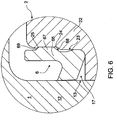
- FIGS. 10 and illustrate sealing rings 405, 406 of a fifth embodiment, which are closely related to the sealing rings 6 of the first embodiment - with particular reference to FIG. 6 .
- the sealing ring 406 has a ring body 461 with a leg 462 and foot 463.
- the toe 463A has a relief angle ⁇ of e.g. 1°- 3° relative to the adjacent wall 413 of the nut body 401.
- the annular bore 423 of the piston 402 is inwardly tapered in a downwards direction, and the portion 465A of the ring body 461 has a corresponding "taper” down to the curved heel 465.
- the sealing rings of the present invention produce an initial sealing action from the action of spring force generated by slight elastic bending of the sealing ring as it is inserted into place. This bending forces the 'heel' of the sealing ring into its respective seat and the 'sealing edge' (of the toe) against the cylinder wall. As hydraulic pressure is increased in the sealed chamber, the sealing mechanism will be further enhanced by increasing inner and outer radial thrust generated as the sealing ring flexes and rolls on its 'heel' to follow outward radial movement of the cylinder wall.
- the alternative designs of the embodiments described and illustrated predict and allow a degree of bending of the seal body to continually align the 'sealing edge' (of the toe) against the cylinder wall.
- sealing of the (leg of the) sealing ring to the 'seal carrier' side of the seal retaining groove can be made in the upper portion (or the leg) of the "L" shape of the seal.
- mechanisms to physically retain the sealing ring can be incorporated as illustrated in FIG. 7 to 9 .
- These mechanisms can also combine a sealing function in the upper portion (or the leg) of the "L' shape of the sealing ring, together with the mechanical location function.
Landscapes
- Engineering & Computer Science (AREA)
- General Engineering & Computer Science (AREA)
- Mechanical Engineering (AREA)
- Physics & Mathematics (AREA)
- Architecture (AREA)
- Fluid Mechanics (AREA)
- Geometry (AREA)
- Sealing Devices (AREA)
- Actuator (AREA)
- Sealing With Elastic Sealing Lips (AREA)
- Pistons, Piston Rings, And Cylinders (AREA)
Claims (5)
- Dichtungsring(5, 6)-Anordnung zur Verwendung in einer hydraulischen Baugruppe des Typs mit einem Kolben (2), der verschiebbar in einem Zylinder aufgenommen ist, wobei sich der Dichtungsring (5, 6) in einem inneren ringförmigen Hohlraum (17) des Zylinders und/oder einem äußeren ringförmigen Hohlraum (18) des Kolbens (2) befindet, wobei die Dichtungsring(5, 6)-Anordnung Folgendes beinhaltet:einen ringförmigen Ringkörper (61) mit einem "im Wesentlichen L-förmigen" Querschnitt, wobei ein Schenkelabschnitt (62) und ein Fußabschnitt (63) durch einen externen Absatz (65) mit einem gekrümmten Profil miteinander verbunden sind, wobei der Fußabschnitt (63) einen Zehenabschnitt (63A) mit einem Freiwinkel (α) im Bereich von 1° bis 5° relativ zu der Mittelachse des Ringkörpers (61) aufweist;den Zylinder mit dem inneren ringförmigen Hohlraum (17), wenn sich der Dichtungsring in dem inneren ringförmigen Hohlraum (17) des Zylinders befindet, und den Kolben mit dem äußeren ringförmigen Hohlraum (18), wenn sich der Dichtungsring in dem äußeren ringförmigen Hohlraum (18) des Kolbens befindet;wobei der externe Absatz (65) ein konvexes Profil aufweist, um eine "rollende" Linie von Dichtungskontakt mit einem Sitz in einem Zylinder oder Kolben auszubilden, an welchem der Ringkörper (61) installiert ist.
- Dichtungsring(5, 6)-Anordnung nach Anspruch 1, wobei:
der Schenkelabschnitt (62) einen Dichtungsvorsprung (66) in der Mitte einer äußeren Dichtungsfläche (62A) des Schenkelabschnitts (62) aufweist, wobei der Dichtungsvorsprung (66) eine zylindrische Dichtungsfläche (67) zwischen einem Paar von geneigten Rampenflächen (68, 69) aufweist, wobei der Dichtungsvorsprung (66) und ein distaler Abschnitt der äußeren Dichtungsfläche (62A) zwei Linien von Dichtungskontakt zwischen dem Ringkörper (61) und dem benachbarten Zylinder oder Kolben ausbilden, an welchem der Ringkörper (61) installiert ist. - Dichtungsring (5, 6)-Anordnung nach Anspruch 1 oder 2, wobei:
der Freiwinkel (α) im Bereich von 1° bis 3° relativ zu der Mittelachse des Ringkörpers (61) liegt. - Dichtungsring(5, 6)-Anordnung nach einem der Ansprüche 1 bis 3, ferner beinhaltend einen Wandabschnitt des Kolbens oder Zylinders, der mit dem Zylinder oder Kolben assoziiert ist, in dem der Dichtungsring installiert ist, wobei:
der Zehenabschnitt (63A) in den Wandabschnitt des Kolbens oder Zylinders eingreift, der mit dem Zylinder oder Kolben assoziiert ist, in dem der Dichtungsring (5, 6) installiert ist, und der Zehenabschnitt (63A) in Richtung eines vollständigen Dichtungskontakts mit dem Wandabschnitt bewegt wird, wenn der Absatz (65) in den Sitz rollt, wenn ein Hydraulikdruck zwischen dem Zylinder und dem Kolben erhöht wird. - Dichtungsring(5, 6)-Anordnung nach einem der Ansprüche 1 bis 4, wobei:
der Dichtungsring (61) einen Vorsprung (66) auf einer äußeren Dichtungsfläche (62A) des Schenkelabschnitts (62) oder dem externen Absatz (65) aufweist, der in einer Vertiefung (24) in dem Zylinder oder Kolben aufgenommen werden kann, in welchem der Dichtungsring (5, 6) sitzt.
Applications Claiming Priority (2)
| Application Number | Priority Date | Filing Date | Title |
|---|---|---|---|
| AU2011900324A AU2011900324A0 (en) | 2011-02-02 | High-pressure sealling ring | |
| PCT/AU2012/000088 WO2012103586A1 (en) | 2011-02-02 | 2012-02-02 | High-pressure sealing ring |
Publications (3)
| Publication Number | Publication Date |
|---|---|
| EP2671004A1 EP2671004A1 (de) | 2013-12-11 |
| EP2671004A4 EP2671004A4 (de) | 2017-02-08 |
| EP2671004B1 true EP2671004B1 (de) | 2020-04-22 |
Family
ID=46602011
Family Applications (1)
| Application Number | Title | Priority Date | Filing Date |
|---|---|---|---|
| EP12742478.6A Active EP2671004B1 (de) | 2011-02-02 | 2012-02-02 | Hockdruck-dichtungsring |
Country Status (8)
| Country | Link |
|---|---|
| US (2) | US20140042714A1 (de) |
| EP (1) | EP2671004B1 (de) |
| JP (1) | JP5802765B2 (de) |
| KR (2) | KR102002520B1 (de) |
| CN (1) | CN103380320B (de) |
| AU (1) | AU2012212396B2 (de) |
| CA (1) | CA2863581C (de) |
| WO (1) | WO2012103586A1 (de) |
Families Citing this family (6)
| Publication number | Priority date | Publication date | Assignee | Title |
|---|---|---|---|---|
| US5882050A (en) * | 1997-04-15 | 1999-03-16 | Williams; Peter C. | Ferrule with relief to reduce galling |
| FR3051878B1 (fr) * | 2016-05-24 | 2018-10-26 | Onis | Etancheite statique haute pression |
| CN108518380B (zh) * | 2018-06-01 | 2024-04-30 | 苏州好特斯模具有限公司 | 快换型立体冷却液压缸 |
| AU2018247208B2 (en) * | 2018-10-09 | 2025-02-27 | Technofast Industries Pty Ltd | Hydraulic Mantle Assembly System for a Gyratory Rock Crusher |
| EP4490403A1 (de) * | 2022-03-10 | 2025-01-15 | Nordex Energy SE & Co. KG | Windturbinenrotorblatt und verfahren zum verbinden zweier rotorblattsegmente |
| CN115749681A (zh) * | 2022-11-29 | 2023-03-07 | 中国海洋石油集团有限公司 | 一种井下安全阀 |
Family Cites Families (34)
| Publication number | Priority date | Publication date | Assignee | Title |
|---|---|---|---|---|
| GB648434A (en) * | 1948-09-01 | 1951-01-03 | Gen Electric Co Ltd | Improvements in or relating to joint-making packing |
| US3218087A (en) * | 1962-07-09 | 1965-11-16 | Boeing Co | Foot seal |
| US3463044A (en) * | 1967-05-05 | 1969-08-26 | Joseph J Rossman | Hydraulic holding devices |
| US3955834A (en) * | 1972-02-11 | 1976-05-11 | Aktiebolaget Svenska Flaktfabriken | Apparatus for connecting ducts with a self-sealing joint |
| GB1475312A (en) * | 1973-10-12 | 1977-06-01 | Angus Co Ltd G | Piston or like sealing or packing |
| US4121838A (en) * | 1973-11-17 | 1978-10-24 | Nippon Piston Ring Co., Ltd. | Shaft seal structure |
| US4262915A (en) * | 1978-04-17 | 1981-04-21 | Commercial Shearing, Inc. | Low friction drag seals |
| US4231578A (en) * | 1979-04-23 | 1980-11-04 | W. S. Shamban & Co. | Seal assembly |
| US4306727A (en) * | 1980-07-24 | 1981-12-22 | Reed Rock Bit Company | Dynamic seal for rolling cutter drill bit |
| FR2501322A1 (fr) * | 1981-03-05 | 1982-09-10 | Mdpa | Joint annulaire a plusieurs fonctions utilisables dans les dispositifs a axe lisse et cylindre concentrique |
| JPS57167563A (en) * | 1981-04-06 | 1982-10-15 | Nissan Motor Co Ltd | Sealing device |
| US4421330A (en) * | 1982-02-08 | 1983-12-20 | Greene, Tweed & Co., Inc. | Antifriction fluid seal assembly |
| US4566702A (en) * | 1985-03-18 | 1986-01-28 | W. S. Shamban & Company | Seal assembly with improved low pressure sealing ring |
| US5046906A (en) * | 1987-09-29 | 1991-09-10 | Bucknell John W | Force applicators |
| FI101498B1 (fi) * | 1995-05-16 | 1998-06-30 | Uponor Bv | Muhviliitos muoviputkia varten |
| AUPO076596A0 (en) * | 1996-07-02 | 1996-07-25 | Bucknell, John Wentworth | Seals for hydraulic assemblies |
| NL1012801C2 (nl) * | 1999-08-10 | 2001-02-23 | Ihc Holland Nv | Schotdoorvoering, zoals in het bijzonder voor het doorvoeren van een schroefas door een waterdicht schot. |
| EP1448338B1 (de) * | 2001-11-30 | 2009-12-23 | Westinghouse Electric Company LLC | Verfahren zum verschliessen eines druckgefässes |
| JP4180829B2 (ja) * | 2002-01-21 | 2008-11-12 | イーグル工業株式会社 | シール装置 |
| EP1718890B1 (de) * | 2004-02-25 | 2015-09-16 | BUCKNELL, John Wentworth | Dichtungen für hydraulische anordnungen |
| US8556557B2 (en) * | 2004-07-08 | 2013-10-15 | Gordon Britton | Hydraulic nut and improved seals therefor |
| US8657299B2 (en) * | 2004-07-15 | 2014-02-25 | John E. Rode | Mounting rings for shafts |
| US7563050B2 (en) * | 2004-07-15 | 2009-07-21 | Temper Corporation | Rings for mounting structures to shafts and methods of using such rings |
| WO2006030557A1 (ja) * | 2004-09-17 | 2006-03-23 | Nippon Valqua Industries, Ltd. | 複合シール材 |
| US7341258B2 (en) * | 2004-09-24 | 2008-03-11 | Greene, Tweed Of Delaware, Inc. | Cammed seal assembly with sealing ring having an angled leg portion and foot portion with elastomeric energizer element |
| US7322579B2 (en) * | 2004-12-07 | 2008-01-29 | Automotive Components Holdings, Llc | Spline shaft seal assembly |
| US7252293B2 (en) * | 2005-02-04 | 2007-08-07 | Press-Seal Gasket Corporation | Two-part gasket for pipe-to-pipe connections |
| FR2890717B1 (fr) * | 2005-09-15 | 2007-11-23 | Aldes Aeraulique Sa | Joint annulaire d'etancheite pour raccord de conduites de circulation de fluide,telles que des conduites d'air |
| DE102007027815A1 (de) * | 2007-06-13 | 2008-12-24 | Federal-Mogul Burscheid Gmbh | Ölabstreifring |
| GB0718993D0 (en) * | 2007-09-28 | 2007-11-07 | Ge Healthcare Bio Sciences Ab | Sealing assembly for a chromatography column |
| WO2010068297A2 (en) * | 2008-12-12 | 2010-06-17 | Flowserve Management Company | Pump seal |
| DE102009022334B4 (de) * | 2009-05-13 | 2023-01-05 | Parker Hannifin Gmbh | Dichtung mit L-förmigem Querschnitt |
| EP2372208B1 (de) * | 2010-03-25 | 2013-05-29 | Tenaris Connections Limited | Gewindeverbindung mit elastomerischem Dichtflansch |
| WO2013131132A1 (en) * | 2012-03-06 | 2013-09-12 | Technofast Industries Pty Ltd | High-capacity radial fit coupling bolts |
-
2012
- 2012-02-02 WO PCT/AU2012/000088 patent/WO2012103586A1/en not_active Ceased
- 2012-02-02 US US13/982,789 patent/US20140042714A1/en not_active Abandoned
- 2012-02-02 JP JP2013552064A patent/JP5802765B2/ja active Active
- 2012-02-02 KR KR1020197003905A patent/KR102002520B1/ko active Active
- 2012-02-02 CN CN201280007570.2A patent/CN103380320B/zh active Active
- 2012-02-02 AU AU2012212396A patent/AU2012212396B2/en active Active
- 2012-02-02 KR KR1020137023209A patent/KR20140044301A/ko not_active Ceased
- 2012-02-02 CA CA2863581A patent/CA2863581C/en active Active
- 2012-02-02 EP EP12742478.6A patent/EP2671004B1/de active Active
-
2017
- 2017-12-01 US US15/829,277 patent/US10801625B2/en active Active
Non-Patent Citations (1)
| Title |
|---|
| None * |
Also Published As
| Publication number | Publication date |
|---|---|
| EP2671004A1 (de) | 2013-12-11 |
| AU2012212396A1 (en) | 2013-09-05 |
| US20180080565A1 (en) | 2018-03-22 |
| US10801625B2 (en) | 2020-10-13 |
| AU2012212396B2 (en) | 2016-11-03 |
| JP5802765B2 (ja) | 2015-11-04 |
| EP2671004A4 (de) | 2017-02-08 |
| CA2863581A1 (en) | 2012-08-09 |
| CN103380320A (zh) | 2013-10-30 |
| KR20190018029A (ko) | 2019-02-20 |
| WO2012103586A1 (en) | 2012-08-09 |
| JP2014508900A (ja) | 2014-04-10 |
| CA2863581C (en) | 2019-04-02 |
| KR102002520B1 (ko) | 2019-07-23 |
| KR20140044301A (ko) | 2014-04-14 |
| US20140042714A1 (en) | 2014-02-13 |
| CN103380320B (zh) | 2016-06-15 |
Similar Documents
| Publication | Publication Date | Title |
|---|---|---|
| US10801625B2 (en) | High-pressure sealing ring | |
| US8191933B2 (en) | Extrusion resistant gasket face seal | |
| KR102502375B1 (ko) | 유체 커플링용 개스킷 및 유체 커플링 | |
| US20120217743A1 (en) | Pipe coupling assembly with sleeve locking tabs and associated methods | |
| JP6955739B2 (ja) | 管継手 | |
| US20140125012A1 (en) | Compressable sealing ring assembly | |
| CN209925622U (zh) | 一种密封圈及球墨铸管试压密封工装 | |
| KR101289874B1 (ko) | 탄성수단과 유동 유체압을 이용한 시트 밀착구조를 구비한 볼밸브 | |
| US20120086175A1 (en) | Method and apparatus for piston-actuated elastomer probe seal in a hydraulic coupling member | |
| US9816614B2 (en) | Seals for hydraulic assemblies | |
| WO2015162581A1 (en) | A valve, and a method for effectively sealing an area between two surfaces in a valve and use thereof | |
| CN111295537B (zh) | 用于铸管试压密封的密封圈和工装组件 | |
| JP5719529B2 (ja) | ユニオン継手およびユニオン継手のシール構造 | |
| KR20120119945A (ko) | 이탈방지 구조의 원터치형 관연결구 | |
| RU94659U1 (ru) | Металлическая прокладка к-образной формы | |
| EP4077998A1 (de) | Untersymmetrischer dichtungsring | |
| RU88096U1 (ru) | Разъемное соединение | |
| RU2280210C1 (ru) | Разъемное соединение | |
| RU77934U1 (ru) | Поворотное соединение трубопровода |
Legal Events
| Date | Code | Title | Description |
|---|---|---|---|
| PUAI | Public reference made under article 153(3) epc to a published international application that has entered the european phase |
Free format text: ORIGINAL CODE: 0009012 |
|
| 17P | Request for examination filed |
Effective date: 20130814 |
|
| AK | Designated contracting states |
Kind code of ref document: A1 Designated state(s): AL AT BE BG CH CY CZ DE DK EE ES FI FR GB GR HR HU IE IS IT LI LT LU LV MC MK MT NL NO PL PT RO RS SE SI SK SM TR |
|
| DAX | Request for extension of the european patent (deleted) | ||
| RA4 | Supplementary search report drawn up and despatched (corrected) |
Effective date: 20170109 |
|
| RIC1 | Information provided on ipc code assigned before grant |
Ipc: F16J 15/46 20060101ALI20170102BHEP Ipc: F16J 15/56 20060101ALI20170102BHEP Ipc: F16B 31/04 20060101ALI20170102BHEP Ipc: F16J 15/48 20060101ALI20170102BHEP Ipc: F16J 15/06 20060101AFI20170102BHEP Ipc: F16J 15/10 20060101ALI20170102BHEP Ipc: F16J 15/08 20060101ALI20170102BHEP |
|
| STAA | Information on the status of an ep patent application or granted ep patent |
Free format text: STATUS: EXAMINATION IS IN PROGRESS |
|
| 17Q | First examination report despatched |
Effective date: 20180928 |
|
| GRAP | Despatch of communication of intention to grant a patent |
Free format text: ORIGINAL CODE: EPIDOSNIGR1 |
|
| STAA | Information on the status of an ep patent application or granted ep patent |
Free format text: STATUS: GRANT OF PATENT IS INTENDED |
|
| INTG | Intention to grant announced |
Effective date: 20191112 |
|
| GRAS | Grant fee paid |
Free format text: ORIGINAL CODE: EPIDOSNIGR3 |
|
| GRAA | (expected) grant |
Free format text: ORIGINAL CODE: 0009210 |
|
| STAA | Information on the status of an ep patent application or granted ep patent |
Free format text: STATUS: THE PATENT HAS BEEN GRANTED |
|
| AK | Designated contracting states |
Kind code of ref document: B1 Designated state(s): AL AT BE BG CH CY CZ DE DK EE ES FI FR GB GR HR HU IE IS IT LI LT LU LV MC MK MT NL NO PL PT RO RS SE SI SK SM TR |
|
| REG | Reference to a national code |
Ref country code: GB Ref legal event code: FG4D |
|
| REG | Reference to a national code |
Ref country code: CH Ref legal event code: EP |
|
| REG | Reference to a national code |
Ref country code: IE Ref legal event code: FG4D |
|
| REG | Reference to a national code |
Ref country code: DE Ref legal event code: R096 Ref document number: 602012069465 Country of ref document: DE |
|
| REG | Reference to a national code |
Ref country code: AT Ref legal event code: REF Ref document number: 1260546 Country of ref document: AT Kind code of ref document: T Effective date: 20200515 |
|
| REG | Reference to a national code |
Ref country code: LT Ref legal event code: MG4D |
|
| REG | Reference to a national code |
Ref country code: NL Ref legal event code: MP Effective date: 20200422 |
|
| PG25 | Lapsed in a contracting state [announced via postgrant information from national office to epo] |
Ref country code: GR Free format text: LAPSE BECAUSE OF FAILURE TO SUBMIT A TRANSLATION OF THE DESCRIPTION OR TO PAY THE FEE WITHIN THE PRESCRIBED TIME-LIMIT Effective date: 20200723 Ref country code: IS Free format text: LAPSE BECAUSE OF FAILURE TO SUBMIT A TRANSLATION OF THE DESCRIPTION OR TO PAY THE FEE WITHIN THE PRESCRIBED TIME-LIMIT Effective date: 20200822 Ref country code: SE Free format text: LAPSE BECAUSE OF FAILURE TO SUBMIT A TRANSLATION OF THE DESCRIPTION OR TO PAY THE FEE WITHIN THE PRESCRIBED TIME-LIMIT Effective date: 20200422 Ref country code: NL Free format text: LAPSE BECAUSE OF FAILURE TO SUBMIT A TRANSLATION OF THE DESCRIPTION OR TO PAY THE FEE WITHIN THE PRESCRIBED TIME-LIMIT Effective date: 20200422 Ref country code: FI Free format text: LAPSE BECAUSE OF FAILURE TO SUBMIT A TRANSLATION OF THE DESCRIPTION OR TO PAY THE FEE WITHIN THE PRESCRIBED TIME-LIMIT Effective date: 20200422 Ref country code: LT Free format text: LAPSE BECAUSE OF FAILURE TO SUBMIT A TRANSLATION OF THE DESCRIPTION OR TO PAY THE FEE WITHIN THE PRESCRIBED TIME-LIMIT Effective date: 20200422 Ref country code: NO Free format text: LAPSE BECAUSE OF FAILURE TO SUBMIT A TRANSLATION OF THE DESCRIPTION OR TO PAY THE FEE WITHIN THE PRESCRIBED TIME-LIMIT Effective date: 20200722 Ref country code: PT Free format text: LAPSE BECAUSE OF FAILURE TO SUBMIT A TRANSLATION OF THE DESCRIPTION OR TO PAY THE FEE WITHIN THE PRESCRIBED TIME-LIMIT Effective date: 20200824 |
|
| REG | Reference to a national code |
Ref country code: AT Ref legal event code: MK05 Ref document number: 1260546 Country of ref document: AT Kind code of ref document: T Effective date: 20200422 |
|
| PG25 | Lapsed in a contracting state [announced via postgrant information from national office to epo] |
Ref country code: HR Free format text: LAPSE BECAUSE OF FAILURE TO SUBMIT A TRANSLATION OF THE DESCRIPTION OR TO PAY THE FEE WITHIN THE PRESCRIBED TIME-LIMIT Effective date: 20200422 Ref country code: LV Free format text: LAPSE BECAUSE OF FAILURE TO SUBMIT A TRANSLATION OF THE DESCRIPTION OR TO PAY THE FEE WITHIN THE PRESCRIBED TIME-LIMIT Effective date: 20200422 Ref country code: RS Free format text: LAPSE BECAUSE OF FAILURE TO SUBMIT A TRANSLATION OF THE DESCRIPTION OR TO PAY THE FEE WITHIN THE PRESCRIBED TIME-LIMIT Effective date: 20200422 Ref country code: BG Free format text: LAPSE BECAUSE OF FAILURE TO SUBMIT A TRANSLATION OF THE DESCRIPTION OR TO PAY THE FEE WITHIN THE PRESCRIBED TIME-LIMIT Effective date: 20200722 |
|
| PG25 | Lapsed in a contracting state [announced via postgrant information from national office to epo] |
Ref country code: AL Free format text: LAPSE BECAUSE OF FAILURE TO SUBMIT A TRANSLATION OF THE DESCRIPTION OR TO PAY THE FEE WITHIN THE PRESCRIBED TIME-LIMIT Effective date: 20200422 |
|
| REG | Reference to a national code |
Ref country code: DE Ref legal event code: R097 Ref document number: 602012069465 Country of ref document: DE |
|
| PG25 | Lapsed in a contracting state [announced via postgrant information from national office to epo] |
Ref country code: ES Free format text: LAPSE BECAUSE OF FAILURE TO SUBMIT A TRANSLATION OF THE DESCRIPTION OR TO PAY THE FEE WITHIN THE PRESCRIBED TIME-LIMIT Effective date: 20200422 Ref country code: CZ Free format text: LAPSE BECAUSE OF FAILURE TO SUBMIT A TRANSLATION OF THE DESCRIPTION OR TO PAY THE FEE WITHIN THE PRESCRIBED TIME-LIMIT Effective date: 20200422 Ref country code: EE Free format text: LAPSE BECAUSE OF FAILURE TO SUBMIT A TRANSLATION OF THE DESCRIPTION OR TO PAY THE FEE WITHIN THE PRESCRIBED TIME-LIMIT Effective date: 20200422 Ref country code: RO Free format text: LAPSE BECAUSE OF FAILURE TO SUBMIT A TRANSLATION OF THE DESCRIPTION OR TO PAY THE FEE WITHIN THE PRESCRIBED TIME-LIMIT Effective date: 20200422 Ref country code: DK Free format text: LAPSE BECAUSE OF FAILURE TO SUBMIT A TRANSLATION OF THE DESCRIPTION OR TO PAY THE FEE WITHIN THE PRESCRIBED TIME-LIMIT Effective date: 20200422 Ref country code: AT Free format text: LAPSE BECAUSE OF FAILURE TO SUBMIT A TRANSLATION OF THE DESCRIPTION OR TO PAY THE FEE WITHIN THE PRESCRIBED TIME-LIMIT Effective date: 20200422 Ref country code: SM Free format text: LAPSE BECAUSE OF FAILURE TO SUBMIT A TRANSLATION OF THE DESCRIPTION OR TO PAY THE FEE WITHIN THE PRESCRIBED TIME-LIMIT Effective date: 20200422 |
|
| PG25 | Lapsed in a contracting state [announced via postgrant information from national office to epo] |
Ref country code: SK Free format text: LAPSE BECAUSE OF FAILURE TO SUBMIT A TRANSLATION OF THE DESCRIPTION OR TO PAY THE FEE WITHIN THE PRESCRIBED TIME-LIMIT Effective date: 20200422 Ref country code: PL Free format text: LAPSE BECAUSE OF FAILURE TO SUBMIT A TRANSLATION OF THE DESCRIPTION OR TO PAY THE FEE WITHIN THE PRESCRIBED TIME-LIMIT Effective date: 20200422 |
|
| PLBE | No opposition filed within time limit |
Free format text: ORIGINAL CODE: 0009261 |
|
| STAA | Information on the status of an ep patent application or granted ep patent |
Free format text: STATUS: NO OPPOSITION FILED WITHIN TIME LIMIT |
|
| 26N | No opposition filed |
Effective date: 20210125 |
|
| PG25 | Lapsed in a contracting state [announced via postgrant information from national office to epo] |
Ref country code: SI Free format text: LAPSE BECAUSE OF FAILURE TO SUBMIT A TRANSLATION OF THE DESCRIPTION OR TO PAY THE FEE WITHIN THE PRESCRIBED TIME-LIMIT Effective date: 20200422 |
|
| PG25 | Lapsed in a contracting state [announced via postgrant information from national office to epo] |
Ref country code: MC Free format text: LAPSE BECAUSE OF FAILURE TO SUBMIT A TRANSLATION OF THE DESCRIPTION OR TO PAY THE FEE WITHIN THE PRESCRIBED TIME-LIMIT Effective date: 20200422 |
|
| REG | Reference to a national code |
Ref country code: BE Ref legal event code: MM Effective date: 20210228 |
|
| PG25 | Lapsed in a contracting state [announced via postgrant information from national office to epo] |
Ref country code: LI Free format text: LAPSE BECAUSE OF NON-PAYMENT OF DUE FEES Effective date: 20210228 Ref country code: LU Free format text: LAPSE BECAUSE OF NON-PAYMENT OF DUE FEES Effective date: 20210202 Ref country code: CH Free format text: LAPSE BECAUSE OF NON-PAYMENT OF DUE FEES Effective date: 20210228 |
|
| PG25 | Lapsed in a contracting state [announced via postgrant information from national office to epo] |
Ref country code: IE Free format text: LAPSE BECAUSE OF NON-PAYMENT OF DUE FEES Effective date: 20210202 |
|
| PG25 | Lapsed in a contracting state [announced via postgrant information from national office to epo] |
Ref country code: BE Free format text: LAPSE BECAUSE OF NON-PAYMENT OF DUE FEES Effective date: 20210228 |
|
| PG25 | Lapsed in a contracting state [announced via postgrant information from national office to epo] |
Ref country code: HU Free format text: LAPSE BECAUSE OF FAILURE TO SUBMIT A TRANSLATION OF THE DESCRIPTION OR TO PAY THE FEE WITHIN THE PRESCRIBED TIME-LIMIT; INVALID AB INITIO Effective date: 20120202 Ref country code: CY Free format text: LAPSE BECAUSE OF FAILURE TO SUBMIT A TRANSLATION OF THE DESCRIPTION OR TO PAY THE FEE WITHIN THE PRESCRIBED TIME-LIMIT Effective date: 20200422 |
|
| P01 | Opt-out of the competence of the unified patent court (upc) registered |
Effective date: 20230601 |
|
| PG25 | Lapsed in a contracting state [announced via postgrant information from national office to epo] |
Ref country code: MK Free format text: LAPSE BECAUSE OF FAILURE TO SUBMIT A TRANSLATION OF THE DESCRIPTION OR TO PAY THE FEE WITHIN THE PRESCRIBED TIME-LIMIT Effective date: 20200422 |
|
| PG25 | Lapsed in a contracting state [announced via postgrant information from national office to epo] |
Ref country code: MT Free format text: LAPSE BECAUSE OF FAILURE TO SUBMIT A TRANSLATION OF THE DESCRIPTION OR TO PAY THE FEE WITHIN THE PRESCRIBED TIME-LIMIT Effective date: 20200422 |
|
| PG25 | Lapsed in a contracting state [announced via postgrant information from national office to epo] |
Ref country code: TR Free format text: LAPSE BECAUSE OF FAILURE TO SUBMIT A TRANSLATION OF THE DESCRIPTION OR TO PAY THE FEE WITHIN THE PRESCRIBED TIME-LIMIT Effective date: 20200422 |
|
| PGFP | Annual fee paid to national office [announced via postgrant information from national office to epo] |
Ref country code: GB Payment date: 20260112 Year of fee payment: 15 |
|
| PGFP | Annual fee paid to national office [announced via postgrant information from national office to epo] |
Ref country code: DE Payment date: 20260107 Year of fee payment: 15 |
|
| PGFP | Annual fee paid to national office [announced via postgrant information from national office to epo] |
Ref country code: IT Payment date: 20260122 Year of fee payment: 15 |
|
| PGFP | Annual fee paid to national office [announced via postgrant information from national office to epo] |
Ref country code: FR Payment date: 20260108 Year of fee payment: 15 |