EP2671028B1 - Injecteur de chambre de combustion de turbine a gaz a double circuit de carburant et chambre de combustion equipee d'au moins un tel injecteur - Google Patents
Injecteur de chambre de combustion de turbine a gaz a double circuit de carburant et chambre de combustion equipee d'au moins un tel injecteur Download PDFInfo
- Publication number
- EP2671028B1 EP2671028B1 EP12706638.9A EP12706638A EP2671028B1 EP 2671028 B1 EP2671028 B1 EP 2671028B1 EP 12706638 A EP12706638 A EP 12706638A EP 2671028 B1 EP2671028 B1 EP 2671028B1
- Authority
- EP
- European Patent Office
- Prior art keywords
- circuit
- injector
- combustion chamber
- injectors
- fuel
- Prior art date
- Legal status (The legal status is an assumption and is not a legal conclusion. Google has not performed a legal analysis and makes no representation as to the accuracy of the status listed.)
- Active
Links
Images

Classifications
-
- F—MECHANICAL ENGINEERING; LIGHTING; HEATING; WEAPONS; BLASTING
- F23—COMBUSTION APPARATUS; COMBUSTION PROCESSES
- F23R—GENERATING COMBUSTION PRODUCTS OF HIGH PRESSURE OR HIGH VELOCITY, e.g. GAS-TURBINE COMBUSTION CHAMBERS
- F23R3/00—Continuous combustion chambers using liquid or gaseous fuel
- F23R3/28—Continuous combustion chambers using liquid or gaseous fuel characterised by the fuel supply
-
- F—MECHANICAL ENGINEERING; LIGHTING; HEATING; WEAPONS; BLASTING
- F23—COMBUSTION APPARATUS; COMBUSTION PROCESSES
- F23R—GENERATING COMBUSTION PRODUCTS OF HIGH PRESSURE OR HIGH VELOCITY, e.g. GAS-TURBINE COMBUSTION CHAMBERS
- F23R3/00—Continuous combustion chambers using liquid or gaseous fuel
- F23R3/28—Continuous combustion chambers using liquid or gaseous fuel characterised by the fuel supply
- F23R3/34—Feeding into different combustion zones
-
- F—MECHANICAL ENGINEERING; LIGHTING; HEATING; WEAPONS; BLASTING
- F23—COMBUSTION APPARATUS; COMBUSTION PROCESSES
- F23D—BURNERS
- F23D11/00—Burners using a direct spraying action of liquid droplets or vaporised liquid into the combustion space
- F23D11/10—Burners using a direct spraying action of liquid droplets or vaporised liquid into the combustion space the spraying being induced by a gaseous medium, e.g. water vapour
- F23D11/101—Burners using a direct spraying action of liquid droplets or vaporised liquid into the combustion space the spraying being induced by a gaseous medium, e.g. water vapour medium and fuel meeting before the burner outlet
- F23D11/102—Burners using a direct spraying action of liquid droplets or vaporised liquid into the combustion space the spraying being induced by a gaseous medium, e.g. water vapour medium and fuel meeting before the burner outlet in an internal mixing chamber
- F23D11/103—Burners using a direct spraying action of liquid droplets or vaporised liquid into the combustion space the spraying being induced by a gaseous medium, e.g. water vapour medium and fuel meeting before the burner outlet in an internal mixing chamber with means creating a swirl inside the mixing chamber
-
- F—MECHANICAL ENGINEERING; LIGHTING; HEATING; WEAPONS; BLASTING
- F23—COMBUSTION APPARATUS; COMBUSTION PROCESSES
- F23D—BURNERS
- F23D11/00—Burners using a direct spraying action of liquid droplets or vaporised liquid into the combustion space
- F23D11/10—Burners using a direct spraying action of liquid droplets or vaporised liquid into the combustion space the spraying being induced by a gaseous medium, e.g. water vapour
- F23D11/106—Burners using a direct spraying action of liquid droplets or vaporised liquid into the combustion space the spraying being induced by a gaseous medium, e.g. water vapour medium and fuel meeting at the burner outlet
- F23D11/107—Burners using a direct spraying action of liquid droplets or vaporised liquid into the combustion space the spraying being induced by a gaseous medium, e.g. water vapour medium and fuel meeting at the burner outlet at least one of both being subjected to a swirling motion
-
- F—MECHANICAL ENGINEERING; LIGHTING; HEATING; WEAPONS; BLASTING
- F23—COMBUSTION APPARATUS; COMBUSTION PROCESSES
- F23R—GENERATING COMBUSTION PRODUCTS OF HIGH PRESSURE OR HIGH VELOCITY, e.g. GAS-TURBINE COMBUSTION CHAMBERS
- F23R3/00—Continuous combustion chambers using liquid or gaseous fuel
- F23R3/02—Continuous combustion chambers using liquid or gaseous fuel characterised by the air-flow or gas-flow configuration
- F23R3/04—Air inlet arrangements
- F23R3/10—Air inlet arrangements for primary air
- F23R3/12—Air inlet arrangements for primary air inducing a vortex
- F23R3/14—Air inlet arrangements for primary air inducing a vortex by using swirl vanes
-
- F—MECHANICAL ENGINEERING; LIGHTING; HEATING; WEAPONS; BLASTING
- F23—COMBUSTION APPARATUS; COMBUSTION PROCESSES
- F23R—GENERATING COMBUSTION PRODUCTS OF HIGH PRESSURE OR HIGH VELOCITY, e.g. GAS-TURBINE COMBUSTION CHAMBERS
- F23R3/00—Continuous combustion chambers using liquid or gaseous fuel
- F23R3/28—Continuous combustion chambers using liquid or gaseous fuel characterised by the fuel supply
- F23R3/34—Feeding into different combustion zones
- F23R3/343—Pilot flames, i.e. fuel nozzles or injectors using only a very small proportion of the total fuel to insure continuous combustion
-
- F—MECHANICAL ENGINEERING; LIGHTING; HEATING; WEAPONS; BLASTING
- F23—COMBUSTION APPARATUS; COMBUSTION PROCESSES
- F23D—BURNERS
- F23D2900/00—Special features of, or arrangements for burners using fluid fuels or solid fuels suspended in a carrier gas
- F23D2900/00014—Pilot burners specially adapted for ignition of main burners in furnaces or gas turbines
-
- F—MECHANICAL ENGINEERING; LIGHTING; HEATING; WEAPONS; BLASTING
- F23—COMBUSTION APPARATUS; COMBUSTION PROCESSES
- F23D—BURNERS
- F23D2900/00—Special features of, or arrangements for burners using fluid fuels or solid fuels suspended in a carrier gas
- F23D2900/00015—Pilot burners specially adapted for low load or transient conditions, e.g. for increasing stability
-
- F—MECHANICAL ENGINEERING; LIGHTING; HEATING; WEAPONS; BLASTING
- F23—COMBUSTION APPARATUS; COMBUSTION PROCESSES
- F23D—BURNERS
- F23D2900/00—Special features of, or arrangements for burners using fluid fuels or solid fuels suspended in a carrier gas
- F23D2900/00016—Preventing or reducing deposit build-up on burner parts, e.g. from carbon
Definitions
- the invention relates to a gas turbine combustion chamber injector, in particular a gas turbine engine, comprising a double fuel injection circuit.
- the invention also relates to a combustion chamber equipped with at least one such dual circuit injector and single circuit injectors.
- a mixture of compressed air and suitable fuel is generally injected into the combustion chamber using a plurality of injectors.
- the injectors are mounted in the wall of a flame tube arranged, preferably at the bottom of the chamber. This makes it possible to homogeneously distribute the mixtures originating from the various injectors.
- a nozzle introduces fuel at the end of a tubing.
- the fuel is adjusted in a centering guide.
- the air comes from the last stage of a compressor of the gas machine and is introduced into the injector annularly.
- Air and fuel are typically introduced into contra-rotated channel swirlers or tendrils, and the fuel particles are sprayed into the air via a mixer.
- the mixture ignited with a candle located at a certain distance, is burned in the chamber.
- the generated gases then have a high kinetic energy, which is exploited to generate propulsion or mechanical energy.
- the ignition of the chamber is provided by two injectors dedicated to start, each starter injector being associated with a candle.
- the other injectors are dedicated to the post-start systems: transient acceleration or deceleration regimes and stabilized flight regimes.
- This architecture requires the availability of specific starter injectors, and therefore an additional mass, specific mounting holes for these injectors on the flame tube that supports all the injectors, as well as the introduction of additional controls which result.
- combustion chambers equipped with injectors having a dual fuel supply circuit, an auxiliary circuit and a main circuit.
- the auxiliary circuit is dedicated to idle operation, that is to say at low load, while the main circuit or both circuits are solicited at intermediate speeds and stabilized. At full throttle, the ratio of flows between the two circuits is reversed and the main circuit becomes dominant or the sole supplier of fuel.
- FR 2 906 868 or FR 2,896,030 filed in the name of the plaintiff.
- Another double circuit injector is known from the patent US 7,513,116 .
- the invention aims to remedy this problem, by proposing a starter injector that can also be used in all flight regimes without cost or additional mass. To do this, this starter injector has a particular configuration of dual fuel circuit and air circuit.
- the present invention relates to a gas turbine combustion chamber injector, having a dual fuel injection circuit and an air circuit.
- the fuel injection circuits consist of a starter fuel circuit, capable of triggering the ignition of the chamber and then operating in all flight regimes, and a main fuel circuit, able to operate in the engine. all the flight regimes after the start.
- the fuel systems have parallel conduits formed in a common tube of longitudinal axis.
- the conduit of the starting circuit opens, at one end, substantially in the center of a spherical injector body extending the common tube.
- the duct houses an injection ramp capable of driving the fuel in rotation before projecting it inside the chamber by a central channel passing through a central swirling wall.
- the conduit of the main circuit opens into an annular channel formed in the body facing nozzle channels arranged radially in the main wall around the central channel.
- the air circuit is guided between two portions of concentric spheres constituted by the injector body and a sheath surrounding the injector body and having an opening through which the whirlpool opens.
- the injector according to the invention has a greatly reduced size thanks to its doubly spherical architecture.
- the central starting circuit is thermally protected from coking by the circulation of fuel in the annular channel of the main circuit.
- the main circuit is itself thermally protected by the flow of peripheral air flowing in the inter-spherical space.
- the swirler is in an inclined position with respect to the longitudinal axis of the injector. This inclination makes it possible to position the end of the starting circuit at the center of the latter and to orient the air and fuel jets in the direction of the candle arranged at the bottom of the chamber.
- the invention also relates to a combustion chamber equipped with at least one double circuit injector presented above and single circuit injectors. All the injectors are mounted in alignment on the casing surrounding the combustion chamber and pass through a flame tube through orifices formed along at least one line parallel to the longitudinal axis of the flame tube.
- the dual circuit injectors are directed towards the spark plug so that these injectors are able to project an air / fuel cone at the outlet of the whirlpool directed towards the bottom of the combustion chamber.
- the combustion chamber is equipped with two non-adjacent dual circuit injectors on the injector line.
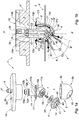
- an injector 1 comprises a fastening flange 10 on a casing 2 of the annular combustion chamber 3, a common shaft tube 11 X'X longitudinal reference of the injector, and a circular swirl 4 central wall 14 and axis of symmetry Y'Y inclined relative to the axis X'X.
- This central wall 14 allows to project, through the opening 15 of a sleeve 5, an air / fuel mixture in a flame tube 6 which bears on the sleeve 5.
- the swirl 4 is dimensioned so that the fins 40 of this whirlpool, regularly distributed around the periphery of the central wall 14, support in a self-adjusting and self-centering manner on the edge of the opening 15.
- the dual fuel injection circuit consists of a starting fuel circuit C1, able to trigger the ignition of the chamber 3 and to operate in all flight regimes, and a main fuel circuit C2, able to work in all flight regimes after starting.
- the circuits C1 and C2 are coupled to fuel supply pipes (not shown). These circuits consist of access bores 2a, 2b formed in the fastening flange 10, in connection with parallel longitudinal conduits, respectively 12a and 12b, extending in the tube 11 bearing on sealing sleeves 13a and 13b housed in this tube. These ducts extend in the tube 11 parallel to the longitudinal axis X'X and open into the combustion chamber 3 through the central wall 14.
- the conduit 12a opens - at one end 12e - substantially in the center of a hemispherical injector body 11s in extension of the tube 11.
- the conduit 12a houses - in a recess cylindrical 21 inclined axis coincides with the Y'Y axis of the whirlpool 4 - a helical fuel rail 7.
- the recess 21 has a conical end 21c coupled through the central wall 14 of the whirlpool 4, to a central channel 41 of axis coincides with the Y'Y axis of the whirlpool 4 or the recess 21. This central channel 41 opens into the combustion chamber 3.
- a nozzle 8 is advantageously mounted in the access bore 2b of the flange 10. This nozzle makes it possible to calibrate the fuel flow which varies according to the flight phases.
- the longitudinal duct 12b is oriented in a final portion 12f parallel to the axis Y'Y and opens into an annular channel 16 formed in the spherical body 11s.
- This annular channel 16 advantageously has two ends 16e. In other words, this channel is not looped on itself. Thus, no "dead" zone where fuel could stagnate is formed.
- the annular channel 16 is brazed to the central wall by means of a suitable solder 20 which reveals the non-looped shape of the annular channel 16.
- This annular channel 16 communicates with nozzle channels 42 arranged radially and distributed equidistantly around of the central channel 41.
- these nozzle channels have the same diameter.
- the radial channels 42 advantageously have an orientation along axes K'K symmetrically inclined with respect to the axis Y'Y of the central channel 41 (see in particular the figure 1b ), and contra-rotation relative to the inclination of the vanes 40 of the swirler 4.
- the number of radial channels 42 is equal to a multiple of the number of vanes 40 of the swirler 4.
- the inlet air flow F E - from the last compression stage - passes through openings 170 formed in a flared lid 17 extending the tube 11, and is then guided in an air circuit C3 circulating in a space inter-spherical "E".
- This space "E” is formed between two portions of concentric spheres formed by the injector body 11s and partially by the sleeve 5 in a spherical portion 5s enveloping the injector body 11s.
- the sheath also has a cylindrical portion with a circular section 5c, which makes it possible to provide support for the flame tube 6 and the flared lid 17 of the tube 11.
- the injector according to the invention has a minimum space requirement thanks to this interpass. -spherical.
- the central starting circuit C1 is thermally protected from coking by the circulation of the fuel in the annular channel 16 of the main circuit C2, this main circuit being itself thermally protected by the flow of peripheral air F flowing in the inter-spherical space "E" of the air circuit C3.
- the air flow F S advantageously forms, passing between the fins 40, an air cone Ca enclosing the fuel outlet cone Cs of the main circuit C2.
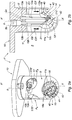
- the tube 11 'does not have a flared lid 17 to form the openings 170 for access to the air flow F E in the circuit C3.
- the tube 11 ' is extended directly by the spherical body 11s.
- the conical end portion 21c of the recess 21 passes through the central wall 14 of the swirler 4 and acts as a central channel 41.
- the partial perspective view illustrates the combustion chamber 3 equipped with injectors mounted on the wall of the flame tube 6: two double circuit injectors 1 shown above and seven single circuit injectors 100.
- the chamber is partially cut to to show some injectors in full and the candle 101 on the side of the bottom 3f of the chamber.
- All the injectors 1, 100 are regularly mounted on the annular periphery of the chamber 3. Orifices 60 were made in the tube 6 to enclose the sleeves 5 of the injectors 1, 100.
- the dual circuit injectors 1 are oriented towards the spark plug 101. Thanks to the inclined orientation of the nozzle channels 42 and the central channels 41, the dual circuit injectors 1 are able to project air / fuel cones Ca / Cs at the outlet of the swirlers to the bottom 3f of the combustion chamber 3. After ignition, the flame goes to the bottom 3f, turns and emerges through the opposite outlet 3s.
- the two dual circuit injectors 1 are separated by a single circuit injector 100 so as to facilitate the orientation of the dual circuit injectors 1 towards the candle 101.
- the body of the injector may form a more or less complete sphere part depending on the opening size or the diameter of the common tube. It is also possible to form several lines of injectors in the flame tube.
Landscapes
- Engineering & Computer Science (AREA)
- Chemical & Material Sciences (AREA)
- Combustion & Propulsion (AREA)
- Mechanical Engineering (AREA)
- General Engineering & Computer Science (AREA)
- Fuel-Injection Apparatus (AREA)
- Ignition Installations For Internal Combustion Engines (AREA)
- Pressure-Spray And Ultrasonic-Wave- Spray Burners (AREA)
- Jet Pumps And Other Pumps (AREA)
Description
- L'invention concerne un injecteur de chambre de combustion de turbine à gaz, en particulier de turbomoteur, comportant un double circuit d'injection de carburant. L'invention concerne également une chambre de combustion équipée d'au moins un tel injecteur à double circuit et d'injecteurs à simple circuit.
- Un mélange d'air comprimé et de carburant approprié est en général injecté dans la chambre de combustion à l'aide d'une pluralité d'injecteurs. Les injecteurs sont montés dans la paroi d'un tube à flamme agencé, de préférence, en fond de chambre. Ceci permet de répartir de manière homogène les mélanges provenant des différents injecteurs.
- Dans chaque injecteur, un gicleur introduit du carburant à l'extrémité d'une tubulure. Le carburant est ajusté dans un guide de centrage. L'air provient du dernier étage d'un compresseur de la machine à gaz et est introduit dans l'injecteur de manière annulaire. L'air et le carburant sont en général introduits dans des tourbillonneurs à canaux orientés en contra-rotation ou des vrilles, puis les particules de carburant sont pulvérisées dans l'air via un mélangeur. Le mélange, enflammé à l'aide d'une bougie située à une distance déterminée, est brûlé dans la chambre. Les gaz générés possèdent alors une haute énergie cinétique, qui est exploitée pour générer de la propulsion ou de l'énergie mécanique.
- De nos jours, l'allumage de la chambre est assuré par deux injecteurs dédiés au démarrage, chaque injecteur de démarrage étant associé à une bougie. Les autres injecteurs sont dédiés aux régimes post démarrage : régimes transitoires d'accélération ou décélération et régimes stabilisés en vol. Cette architecture nécessite de disposer d'injecteurs de démarrage spécifiques, et donc une masse supplémentaire, des orifices de montage spécifiques pour ces injecteurs sur le tube à flamme qui supporte l'ensemble des injecteurs, ainsi que la mise en place de contrôles supplémentaires qui en résultent.
- Il existe par ailleurs des chambres de combustion équipées d'injecteurs ayant un double circuit d'alimentation en carburant, un circuit auxiliaire et un circuit principale. Le circuit auxiliaire est dédié au fonctionnement au ralenti, c'est-à-dire à faible charge, alors que le circuit principal ou les deux circuits sont sollicités aux régimes intermédiaires et stabilisés. Au régime plein gaz, le rapport des débits entre les deux circuits s'inversent et le circuit principal devient prépondérant ou l'unique fournisseur de carburant. Une telle répartition est décrite par exemple dans le document de brevet
FR 2 906 868 FR 2 896 030 US 7 513 116 . - Cependant ces injecteurs à double circuit ne sont pas adaptés pour être utilisés en phase de démarrage car leur structure ne permet pas d'éjection de mélange à vitesse élevée au démarrage. C'est pourquoi la présence d'injecteurs spécifiques perdure avec les inconvénients cités plus haut.
- L'invention vise à remédier à ce problème, en proposant un injecteur de démarrage qui puisse également être utilisé dans tous les régimes de vol sans coût ni masse supplémentaire. Pour ce faire, cet injecteur de démarrage possède une configuration particulière de double circuit de carburant et de circuit d'air.
- Plus précisément, la présente invention a pour objet un injecteur de chambre de combustion de turbine à gaz, comportant un double circuit d'injection de carburant et un circuit d'air. Les circuits d'injection de carburant se composent d'un circuit de carburant de démarrage, apte à déclencher l'allumage de la chambre puis à fonctionner dans tous les régimes de vol, et d'un circuit de carburant principal, apte à fonctionner dans tous les régimes de vol suite au démarrage. Les circuits de carburant ont des conduits parallèles formés dans un tube commun d'axe longitudinal. Le conduit du circuit de démarrage débouche, en une extrémité, sensiblement au centre d'un corps d'injecteur sphérique prolongeant le tube commun. En cette extrémité, le conduit loge une rampe d'injection apte à entraîner le carburant en rotation avant de le projeter à l'intérieur de la chambre par un canal central traversant une paroi centrale de tourbillonneur. Le conduit du circuit principal débouche dans un canal annulaire formé dans le corps en regard de canaux gicleurs agencés radialement dans la paroi principale autour du canal central. Le circuit d'air est guidé entre deux portions de sphères concentriques constituées par le corps d'injecteur et un fourreau enveloppant le corps d'injecteur et présentant une ouverture par laquelle débouche le tourbillonneur.
- Ainsi l'injecteur selon l'invention présente un encombrement fortement réduit grâce à son architecture doublement sphérique.
- De plus, le circuit de démarrage central est thermiquement protégé de la cokéfaction par la circulation du carburant dans le canal annulaire du circuit principal. Le circuit principal est lui-même thermiquement protégé par le flux d'air périphérique circulant dans l'espace inter-sphérique.
- Avantageusement, le tourbillonneur est en position inclinée par rapport à l'axe longitudinal de l'injecteur. Cette inclinaison permet de positionner l'extrémité du circuit de démarrage au centre de celui-ci et d'orienter les jets d'air et de carburant en direction de la bougie agencée en fond de chambre.
- Selon des formes de réalisation particulières :
- le conduit de carburant du circuit de démarrage présente en son extrémité un évidement cylindrique pour loger la rampe ;
- le canal central est de forme conique se rétrécissant vers l'intérieur de la chambre de combustion dans laquelle il débouche ;
- les canaux radiaux présentent une orientation inclinée par rapport à l'axe du canal central et en contra-rotation par rapport à l'inclinaison des ailettes du tourbillonneur ; le flux d'air en sortie d'injecteur forme alors un cône d'air enveloppant le cône de carburant du circuit principal ;
- la rampe d'injection du circuit de démarrage est hélicoïdale ;
- le canal annulaire du circuit de carburant principal n'est pas bouclé sur lui-même et présente des extrémités afin de ne pas former de zone « morte » où le carburant pourrait stagner ;
- le nombre de canaux radiaux est égal à un multiple du nombre d'ailettes du tourbillonneur.
- L'invention se rapport également à une chambre de combustion équipée d'au moins un injecteur à double circuit présenté ci-dessus et d'injecteurs à simple circuit. Tous les injecteurs sont montés en alignement sur le carter enveloppant la chambre de combustion et traversent un tube à flamme par des orifices formés le long d'au moins une ligne parallèle à l'axe longitudinal du tube à flamme.
- Les injecteurs à double circuit sont orientés vers la bougie d'allumage de sorte que ces injecteurs sont aptes à projeter un cône air/carburant en sortie du tourbillonneur dirigé vers le fond de la chambre de combustion.
- Dans un mode de réalisation préféré, la chambre de combustion est équipée de deux injecteurs à double circuit non adjacents sur la lignée d'injecteurs.
- D'autres caractéristiques et avantages de la présente invention apparaîtront à la lecture de l'exemple détaillé de réalisation qui suit, en référence aux figures annexées qui représentent, respectivement :
- les
figures 1a et 1b , une vue éclatée et une vue en coupe d'un exemple d'injecteur à double circuit selon l'invention, - les
figures 2a et 2b , une vue en perspective et une vue en coupe d'une variante de l'exemple précédent ; et - la
figure 3 , une vue en perspective partielle d'une chambre de combustion équipée d'injecteurs à double circuit présentés ci-dessus et d'injecteurs à simple circuit. - En référence à la vue éclatée et à la vue en coupe des figures respectives 1a et 1b, un injecteur 1 selon l'invention comporte une bride de fixation 10 sur un carter 2 de chambre de combustion annulaire 3, un tube commun 11 d'axe longitudinal X'X de référence de l'injecteur, et un tourbillonneur circulaire 4 de paroi centrale 14 et d'axe de symétrie Y'Y incliné par rapport à l'axe X'X. Cette paroi centrale 14 permet de projeter, à travers l'ouverture 15 d'un fourreau 5, un mélange air/carburant dans un tube à flamme 6 qui prend appui sur le fourreau 5. Le tourbillonneur 4 est dimensionné de sorte que les ailettes 40 de ce tourbillonneur, régulièrement réparties en périphérie de la paroi centrale 14, prennent appui de manière auto-ajustée et autocentrée sur le bord de l'ouverture 15.
- Le double circuit d'injection de carburant se compose d'un circuit de carburant de démarrage C1, apte à déclencher l'allumage de la chambre 3 et à fonctionner dans tous les régimes de vol, et d'un circuit de carburant principal C2, apte à fonctionner dans tous les régimes de vol suite au démarrage.
- Les circuits C1 et C2 sont couplés à des tubulures d'alimentation en carburant (non représentés). Ces circuits sont constitués d'alésages d'accès 2a, 2b formés dans la bride de fixation 10, en liaison avec des conduits longitudinaux parallèles, respectivement 12a et 12b, s'étendant dans le tube 11 en appui sur des douilles d'étanchéité 13a et 13b logées dans ce tube. Ces conduits s'étendent dans le tube 11 parallèlement à l'axe longitudinal X'X et débouchent dans la chambre de combustion 3 par la paroi centrale 14.
- Concernant le circuit de démarrage C1, le conduit 12a débouche - en une extrémité 12e - sensiblement au centre d'un corps d'injecteur hémisphérique 11s en prolongement du tube 11. De plus, à cette extrémité, le conduit 12a loge - dans un évidement cylindrique 21 d'axe incliné confondu avec l'axe Y'Y du tourbillonneur 4 - une rampe hélicoïdale de carburant 7. Avantageusement, l'évidement 21 présente une extrémité conique 21c couplée, à travers la paroi centrale 14 du tourbillonneur 4, à un canal central 41 d'axe confondu avec l'axe Y'Y du tourbillonneur 4 ou de l'évidement 21. Ce canal central 41 débouche dans la chambre de combustion 3.
- Concernant le circuit principal C2, un gicleur 8 est avantageusement monté dans l'alésage d'accès 2b de la bride 10. Ce gicleur permet de calibrer le débit de carburant qui varie suivant les phases de vol. Après un coude 12c, le conduit longitudinal 12b est orienté dans une portion finale 12f parallèlement à l'axe Y'Y et débouche dans un canal annulaire 16 réalisé dans le corps sphérique 11s. Ce canal annulaire 16 présente avantageusement deux extrémités 16e. En d'autres termes, ce canal n'est pas bouclé sur lui-même. Ainsi, aucune zone « morte » où le carburant pourrait stagner ne se forme.
- Le canal annulaire 16 est brasé sur la paroi centrale à l'aide d'une brasure appropriée 20 qui laisse apparaître la forme non bouclée du canal annulaire 16. Ce canal annulaire 16 communique avec des canaux gicleurs 42 agencés radialement et répartis de manière équidistante autour du canal central 41. Avantageusement, ces canaux gicleurs ont le même diamètre. Les canaux radiaux 42 présentent avantageusement une orientation selon des axes K'K symétriquement inclinés par rapport à l'axe Y'Y du canal central 41 (voir en particulier la
figure 1b ), et en contra-rotation par rapport à l'inclinaison des ailettes 40 du tourbillonneur 4. Avantageusement, le nombre de canaux radiaux 42 est égal à un multiple du nombre d'ailettes 40 du tourbillonneur 4. - Par ailleurs, le flux d'air en entrée FE - provenant du dernier étage de compression - traverse des ouvertures 170 formées dans un couvercle évasé 17 prolongeant le tube 11, et est ensuite guidé dans un circuit d'air C3 circulant dans un espace inter-sphérique « E ». Cet espace « E » est formé entre deux portions de sphères concentriques formées par le corps d'injecteur 11s et partiellement par le fourreau 5 dans une partie sphérique 5s enveloppant le corps d'injecteur 11s. Le fourreau présente également une partie cylindrique à section circulaire 5c, qui permet d'assurer un appui au tube à flamme 6 et au couvercle évasé 17 du tube 11. Ainsi l'injecteur selon l'invention présente un encombrement minimal grâce à ce passage inter-sphérique.
- De plus, le circuit de démarrage central C1 est thermiquement protégé de la cokéfaction par la circulation du carburant dans le canal annulaire 16 du circuit principal C2, ce circuit principal étant lui-même thermiquement protégé par le flux d'air périphérique F circulant dans l'espace inter-sphérique « E » du circuit d'air C3.
- En sortie d'injecteur 1, le flux d'air FS forme avantageusement, en passant entre les ailettes 40, un cône d'air Ca enveloppant le cône de sortie de carburant Cs du circuit principal C2.
- Selon une variante de réalisation en référence aux vues en perspective et en coupe des
figures 2a et 2b , l'injecteur illustré 1' reprend des éléments de l'exemple précédent. Ces élément identiques sont donc représentés avec les mêmes signes de référence : la description précédente de ces éléments est applicable directement auxfigures 2a et 2b dans leur structure et leur fonction. - Les modifications proviennent essentiellement de la configuration de la liaison entre le tube longitudinal 11 et le fourreau 5. Dans l'exemple illustré aux
figure 2a et 2b , le tube 11' ne présente pas de couvercle évasé 17 pour former les ouvertures 170 d'accès du flux d'air FE dans le circuit C3. Ici, le tube 11' est prolongé directement par le corps sphérique 11s. Et le fourreau 5' se prolonge dans sa partie cylindrique jusqu'à venir se fixer sur la bride 10. Les ouvertures 170' de passage du flux d'air FE dans le circuit C3' sont alors pratiquées dans la partie cylindrique du fourreau 5', du côté de la bride 10. La partie d'extrémité conique 21c de l'évidement 21 traverse la paroi centrale 14 du tourbillonneur 4 et fait fonction de canal central 41. - En référence à la
figure 3 , la vue en perspective partielle illustre la chambre de combustion 3 équipée d'injecteurs montés sur la paroi du tube à flamme 6 : deux injecteurs à double circuit 1 présentés ci-dessus et sept injecteurs à simple circuit 100. La chambre est partiellement écorchée afin de faire apparaître certains injecteurs en entier et la bougie 101 du côté du fond 3f de la chambre. - Tous les injecteurs 1, 100 sont montés régulièrement sur le pourtour annulaire de la chambre 3. Des orifices 60 ont été pratiqués dans le tube 6 pour enserrer les fourreaux 5 des injecteurs 1, 100.
- Les injecteurs à double circuit 1 sont orientés vers la bougie d'allumage 101. Grâce à l'orientation inclinée des canaux gicleurs 42 et des canaux centraux 41, les injecteurs à double circuit 1 sont aptes à projeter des cônes air/carburant Ca/Cs en sortie des tourbillonneurs vers le fond 3f de la chambre de combustion 3. Après allumage, la flamme se dirige vers le fond 3f, se retourne et ressort par la sortie opposée 3s.
- Dans l'exemple illustré, les deux injecteurs à double circuit 1 sont séparés par un injecteur simple circuit 100 de sorte à faciliter l'orientation des injecteurs à double circuit 1 vers la bougie 101.
- L'invention n'est pas limitée à l'exemple de réalisation décrit et représenté. Par exemple, le corps de l'injecteur peut former une partie de sphère plus ou moins complète suivant la dimension d'ouverture ou le diamètre du tube commun. Il est par ailleurs possible de former plusieurs lignes d'injecteurs dans le tube à flamme.
Claims (11)
- Injecteur (1, 1') de chambre de combustion (3) de turbine à gaz, comportant un double circuit d'injection de carburant (C1, C2) et un circuit d'air (C3), dans lequel les circuits d'injection de carburant (C1, C2) se composent d'un circuit de carburant de démarrage (C1), apte à déclencher l'allumage de la chambre (3) puis à fonctionner dans tous les régimes de vol, et d'un circuit de carburant principal (C2), apte à fonctionner dans tous les régimes de vol suite au démarrage, dans lequel les circuits de carburant (C1, C2) ont des conduits parallèles (12a, 12b) formés dans un tube commun (11, 11') d'axe longitudinal (X'X), dans lequel le conduit du circuit de démarrage (12a) débouche, en une extrémité (12e), sensiblement au centre d'un corps d'injecteur sphérique (11s) prolongeant le tube commun (11, 11'), dans lequel, en cette extrémité (12e), le conduit loge une rampe d'injection (7) apte à entraîner le carburant en rotation avant de le projeter à l'intérieur de la chambre (3) par un canal central (41) traversant une paroi centrale (14) de tourbillonneur (4), dans lequel le conduit (12b) du circuit principal (C2) débouche dans un canal annulaire (16) formé dans le corps (11s) en regard de canaux gicleurs (42) agencés radialement dans la paroi centrale (14) autour du canal central (41), et dans lequel le circuit d'air (C3) est guidé entre deux portions de sphères concentriques constituées par le corps d'injecteur (11s) et un fourreau (5, 5') enveloppant le corps d'injecteur (11s) et présentant une ouverture (15) par laquelle débouche le tourbillonneur (4).
- Injecteur selon la revendication 1, dans lequel le tourbillonneur (4) est en position inclinée (Y'Y) par rapport à l'axe longitudinal de l'injecteur (X'X) afin de positionner l'extrémité (12e) du circuit de démarrage (12a) au centre de celui-ci et d'orienter les jets d'air (Ca) et de carburant (Cs) au sortir de l'injecteur dans une direction privilégiée à l'intérieur de la chambre, définie comme la direction d'une bougie (101) agencée en fond (3f) de la chambre de combustion (3).
- Injecteur selon l'une des revendications 1 ou 2, dans lequel le conduit (12a) du circuit de démarrage (C1) présente en son extrémité (12e) un évidement cylindrique (21) pour loger la rampe (7).
- Injecteur selon l'une quelconque des revendications précédentes, dans lequel le canal central (41) est de forme conique, se rétrécissant vers l'intérieur de la chambre de combustion (3) dans laquelle il débouche.
- Injecteur selon l'une quelconque des revendications précédentes, dans lequel, le tourbillonneur (4) comportant des ailettes inclinées (40), les canaux radiaux (42) présentent une orientation inclinée (K'K) par rapport à l'axe (Y'Y) du canal central (41) et en contra-rotation par rapport à l'inclinaison des ailettes (40) du tourbillonneur (4).
- Injecteur selon l'une quelconque des revendications précédentes, dans lequel la rampe d'injection (7) du circuit de démarrage (C1) est hélicoïdale.
- Injecteur selon l'une quelconque des revendications précédentes, dans lequel le canal annulaire (16) du circuit de carburant principal (C2) n'est pas bouclé sur lui-même et présente des extrémités (16e) afin de ne pas former de zone « morte » où le carburant pourrait stagner.
- Injecteur selon l'une quelconque des revendications 5 à 7, dans lequel le nombre de canaux radiaux (42) est égal à un multiple du nombre d'ailettes (40) du tourbillonneur (4).
- Chambre de combustion équipée d'au moins un injecteur à double circuit (1, 1') selon l'une quelconque des revendications précédentes, et d'injecteurs à simple circuit (100), dans laquelle tous les injecteurs (1,1' ; 100) sont montés en alignement sur le carter (2) enveloppant la chambre de combustion (3) et traversent un tube à flamme (6) par des orifices (60) formés le long d'au moins une ligne parallèle à l'axe longitudinal du tube à flamme (6).
- Chambre de combustion selon la revendication précédente, dans laquelle les injecteurs à double circuit (1, 1') sont orientés vers la bougie d'allumage (101) de sorte que ces injecteurs sont aptes à projeter un cône air/carburant (Ca, Cs) en sortie du tourbillonneur (4) dirigé vers le fond (3f) de la chambre de combustion (3).
- Chambre de combustion selon l'une des revendications 9 ou 10, équipée de deux injecteurs à double circuit (1, 1') non adjacents sur la lignée d'injecteurs.
Priority Applications (1)
| Application Number | Priority Date | Filing Date | Title |
|---|---|---|---|
| PL12706638T PL2671028T3 (pl) | 2011-02-02 | 2012-01-27 | Wtryskiwacz komory spalania turbiny gazowej z podwójnym obwodem paliwa i komora spalania wyposażona w co najmniej jeden taki wtryskiwacz |
Applications Claiming Priority (2)
| Application Number | Priority Date | Filing Date | Title |
|---|---|---|---|
| FR1150807A FR2971039B1 (fr) | 2011-02-02 | 2011-02-02 | Injecteur de chambre de combustion de turbine a gaz a double circuit de carburant et chambre de combustion equipee d'au moins un tel injecteur |
| PCT/FR2012/050177 WO2012104525A1 (fr) | 2011-02-02 | 2012-01-27 | Injecteur de chambre de combustion de turbine a gaz a double circuit de carburant et chambre de combustion equipee d'au moins un tel injecteur |
Publications (2)
| Publication Number | Publication Date |
|---|---|
| EP2671028A1 EP2671028A1 (fr) | 2013-12-11 |
| EP2671028B1 true EP2671028B1 (fr) | 2018-07-25 |
Family
ID=45774260
Family Applications (1)
| Application Number | Title | Priority Date | Filing Date |
|---|---|---|---|
| EP12706638.9A Active EP2671028B1 (fr) | 2011-02-02 | 2012-01-27 | Injecteur de chambre de combustion de turbine a gaz a double circuit de carburant et chambre de combustion equipee d'au moins un tel injecteur |
Country Status (11)
| Country | Link |
|---|---|
| US (1) | US9347667B2 (fr) |
| EP (1) | EP2671028B1 (fr) |
| JP (1) | JP5985514B2 (fr) |
| KR (1) | KR101877591B1 (fr) |
| CN (1) | CN103354890B (fr) |
| CA (1) | CA2825864C (fr) |
| ES (1) | ES2686560T3 (fr) |
| FR (1) | FR2971039B1 (fr) |
| PL (1) | PL2671028T3 (fr) |
| RU (1) | RU2584741C2 (fr) |
| WO (1) | WO2012104525A1 (fr) |
Families Citing this family (24)
| Publication number | Priority date | Publication date | Assignee | Title |
|---|---|---|---|---|
| FR2996288B1 (fr) * | 2012-10-01 | 2014-09-12 | Turbomeca | Injecteur a double circuit de chambre de combustion de turbomachine. |
| FR2996289B1 (fr) * | 2012-10-01 | 2018-10-12 | Turbomeca | Chambre de combustion comprenant un tube a flamme fixe au moyen de trois elements de centrage. |
| FR3001525B1 (fr) * | 2013-01-29 | 2016-12-09 | Turbomeca | Procede de gestion de la consommation de carburant d un ensemble bimoteur et ensemble associe |
| FR3001497B1 (fr) * | 2013-01-29 | 2016-05-13 | Turbomeca | Ensemble de combustion de turbomachine comprenant un circuit d alimentation de carburant ameliore |
| EP2951505A4 (fr) * | 2013-02-01 | 2016-01-06 | Hamilton Sundstrand Corp | Injecteur de carburant pour démarrage et fonctionnement à haute altitude d'un moteur à turbine à gaz |
| US9404422B2 (en) * | 2013-05-23 | 2016-08-02 | Honeywell International Inc. | Gas turbine fuel injector having flow guide for receiving air flow |
| EP3022492A4 (fr) * | 2013-07-15 | 2017-02-22 | Hamilton Sundstrand Corporation | Système, appareil et procédé de combustion |
| US9625156B2 (en) * | 2013-10-30 | 2017-04-18 | Honeywell International Inc. | Gas turbine engines having fuel injector shrouds with interior ribs |
| FR3017693B1 (fr) * | 2014-02-19 | 2019-07-26 | Safran Helicopter Engines | Chambre de combustion de turbomachine |
| CN104019475A (zh) * | 2014-06-23 | 2014-09-03 | 叶祖湘 | 一种装有燃烧机系统的大小灶具 |
| FR3022613B1 (fr) * | 2014-06-24 | 2019-04-19 | Safran Helicopter Engines | Bossage pour chambre de combustion. |
| FR3050255B1 (fr) * | 2016-04-13 | 2019-10-25 | Safran Helicopter Engines | Injecteurs ameliores pour chambre de combustion de turbine a gaz |
| FR3059047B1 (fr) * | 2016-11-21 | 2020-08-28 | Safran Helicopter Engines | Injecteur de chambre de combustion pour une turbomachine et son procede de fabrication |
| FR3067444B1 (fr) * | 2017-06-12 | 2019-12-27 | Safran Helicopter Engines | Architecture de combustion de carburant de turbomachine comportant des moyens de deflexion |
| FR3068113B1 (fr) | 2017-06-27 | 2019-08-23 | Safran Helicopter Engines | Injecteur de carburant a jet plat pour une turbomachine d'aeronef |
| US10816211B2 (en) * | 2017-08-25 | 2020-10-27 | Honeywell International Inc. | Axially staged rich quench lean combustion system |
| FR3081211B1 (fr) * | 2018-05-16 | 2021-02-26 | Safran Aircraft Engines | Ensemble pour une chambre de combustion de turbomachine |
| CN109185924B (zh) * | 2018-08-03 | 2023-09-12 | 新奥能源动力科技(上海)有限公司 | 燃烧室的头部装置、燃烧室及燃气轮机 |
| CN109185923B (zh) * | 2018-08-03 | 2023-09-12 | 新奥能源动力科技(上海)有限公司 | 一种燃烧室头部装置、燃烧室及燃气轮机 |
| FR3087250B1 (fr) | 2018-10-11 | 2020-09-25 | Safran Helicopter Engines | Injecteur de carburant monobloc a jet plat pour une turbomachine d'aeronef et son procede de fabrication |
| RU187491U1 (ru) * | 2018-11-15 | 2019-03-11 | Публичное Акционерное Общество "Одк-Сатурн" | Испарительная камера сгорания газотурбинного двигателя |
| FR3099231B1 (fr) | 2019-07-24 | 2022-08-12 | Safran Helicopter Engines | Injecteur de carburant a circuit de purge pour une turbomachine d’aeronef |
| US11988386B2 (en) | 2021-12-03 | 2024-05-21 | Honeywell International Inc. | Gas turbine engine injector module with thermally coupled fuel lines having respective outlets |
| US12117174B2 (en) * | 2023-02-14 | 2024-10-15 | Collins Engine Nozzles, Inc. | Combustor section support structures |
Family Cites Families (11)
| Publication number | Priority date | Publication date | Assignee | Title |
|---|---|---|---|---|
| US4817389A (en) * | 1987-09-24 | 1989-04-04 | United Technologies Corporation | Fuel injection system |
| SU1560923A1 (ru) * | 1988-06-29 | 1990-04-30 | Войсковая часть 27177 | Камера сгорани газотурбинного двигател |
| US7513116B2 (en) * | 2004-11-09 | 2009-04-07 | Woodward Fst, Inc. | Gas turbine engine fuel injector having a fuel swirler |
| JP3958767B2 (ja) * | 2005-03-18 | 2007-08-15 | 川崎重工業株式会社 | ガスタービン燃焼器およびその着火方法 |
| US7624576B2 (en) * | 2005-07-18 | 2009-12-01 | Pratt & Whitney Canada Corporation | Low smoke and emissions fuel nozzle |
| FR2896030B1 (fr) * | 2006-01-09 | 2008-04-18 | Snecma Sa | Refroidissement d'un dispositif d'injection multimode pour chambre de combustion, notamment d'un turboreacteur |
| US20070193272A1 (en) * | 2006-02-21 | 2007-08-23 | Woodward Fst, Inc. | Gas turbine engine fuel injector |
| FR2906868B1 (fr) * | 2006-10-06 | 2011-11-18 | Snecma | Injecteur de carburant pour chambre de combustion de moteur a turbine a gaz |
| US7908864B2 (en) * | 2006-10-06 | 2011-03-22 | General Electric Company | Combustor nozzle for a fuel-flexible combustion system |
| FR2911667B1 (fr) * | 2007-01-23 | 2009-10-02 | Snecma Sa | Systeme d'injection de carburant a double injecteur. |
| US9513009B2 (en) * | 2009-02-18 | 2016-12-06 | Rolls-Royce Plc | Fuel nozzle having aerodynamically shaped helical turning vanes |
-
2011
- 2011-02-02 FR FR1150807A patent/FR2971039B1/fr active Active
-
2012
- 2012-01-27 ES ES12706638.9T patent/ES2686560T3/es active Active
- 2012-01-27 WO PCT/FR2012/050177 patent/WO2012104525A1/fr not_active Ceased
- 2012-01-27 JP JP2013552244A patent/JP5985514B2/ja not_active Expired - Fee Related
- 2012-01-27 EP EP12706638.9A patent/EP2671028B1/fr active Active
- 2012-01-27 US US13/982,608 patent/US9347667B2/en active Active
- 2012-01-27 CA CA2825864A patent/CA2825864C/fr not_active Expired - Fee Related
- 2012-01-27 KR KR1020137022157A patent/KR101877591B1/ko not_active Expired - Fee Related
- 2012-01-27 PL PL12706638T patent/PL2671028T3/pl unknown
- 2012-01-27 RU RU2013139354/06A patent/RU2584741C2/ru active
- 2012-01-27 CN CN201280007105.9A patent/CN103354890B/zh active Active
Non-Patent Citations (1)
| Title |
|---|
| None * |
Also Published As
| Publication number | Publication date |
|---|---|
| CN103354890B (zh) | 2016-06-29 |
| FR2971039A1 (fr) | 2012-08-03 |
| FR2971039B1 (fr) | 2013-01-11 |
| RU2013139354A (ru) | 2015-03-10 |
| EP2671028A1 (fr) | 2013-12-11 |
| CN103354890A (zh) | 2013-10-16 |
| CA2825864A1 (fr) | 2012-09-09 |
| RU2584741C2 (ru) | 2016-05-20 |
| PL2671028T3 (pl) | 2018-11-30 |
| WO2012104525A1 (fr) | 2012-08-09 |
| US9347667B2 (en) | 2016-05-24 |
| CA2825864C (fr) | 2019-05-21 |
| JP5985514B2 (ja) | 2016-09-06 |
| KR101877591B1 (ko) | 2018-07-12 |
| ES2686560T3 (es) | 2018-10-18 |
| KR20140008350A (ko) | 2014-01-21 |
| US20130305726A1 (en) | 2013-11-21 |
| JP2014504696A (ja) | 2014-02-24 |
Similar Documents
| Publication | Publication Date | Title |
|---|---|---|
| CA2825864C (fr) | Injecteur de chambre de combustion de turbine a gaz a double circuit de carburant et chambre de combustion equipee d'au moins un tel injecteur | |
| CA2593186C (fr) | Dispositif d'injection d'un melange d'air et de carburant, chambre de combustion et turbomachine munies d'un tel dispositif | |
| EP1806535B1 (fr) | Système d'injection multimode pour chambre de combustion, notamment d'un turboréacteur | |
| CA2572857C (fr) | Refroidissement d'un dispositif d'injection multimode pour chambre de combustion, notamment d'un turboreacteur | |
| EP2071242B1 (fr) | Système d'injection d'un mélange d'air et de carburant dans une chambre de combustion de turbomachine | |
| CA2588952C (fr) | Chambre de combustion d'une turbomachine | |
| EP1314933B1 (fr) | Système d'injection multi-étages d'un mélange air/carburant dans une chambre de combustion de turbomachine | |
| EP1923636B1 (fr) | Dispositif d'injection d'un mélange d'air et de carburant, chambre de combustion et turbomachine munies d'un tel dispositif | |
| FR2931203A1 (fr) | Injecteur de carburant pour turbine a gaz et son procede de fabrication | |
| WO2017072451A1 (fr) | Systeme d'injection aerodynamique pour turbomachine d'aeronef, a melange air/carburant ameliore | |
| CA2907533C (fr) | Systeme d'injection pour chambre de combustion de turbomachine comportant une paroi annulaire a profil interne convergent | |
| WO2020144416A1 (fr) | Systeme d'injection pour turbomachine, comprenant une vrille et des trous tourbillonnaires de bol melangeur | |
| EP3784958B1 (fr) | Système d'injection pour une chambre annulaire de combustion de turbomachine | |
| EP1770333B1 (fr) | Bras d'injecteur anti-cokéfaction | |
| FR2948749A1 (fr) | Systeme d'injection de carburant pour une chambre de combustion de turbomachine | |
| FR3033030A1 (fr) | Systeme d'injection d'un melange air-carburant dans une chambre de combustion de turbomachine d'aeronef, comprenant un venturi perfore de trous d'injection d'air | |
| FR2957659A1 (fr) | Systeme d'injection pour chambre de combustion de turbomachine, comprenant des moyens d'injection de carburant en sortie d'une double vrille d'admission d'air | |
| FR2975466A1 (fr) | Chambre annulaire de combustion pour une turbomachine | |
| FR3165611A1 (fr) | Ensemble à performances améliorées pour injecter un mélange d'air et de carburant dans une chambre de combustion d'une turbomachine d'aéronef | |
| FR3057648A1 (fr) | Systeme d'injection pauvre de chambre de combustion de turbomachine |
Legal Events
| Date | Code | Title | Description |
|---|---|---|---|
| PUAI | Public reference made under article 153(3) epc to a published international application that has entered the european phase |
Free format text: ORIGINAL CODE: 0009012 |
|
| 17P | Request for examination filed |
Effective date: 20130830 |
|
| AK | Designated contracting states |
Kind code of ref document: A1 Designated state(s): AL AT BE BG CH CY CZ DE DK EE ES FI FR GB GR HR HU IE IS IT LI LT LU LV MC MK MT NL NO PL PT RO RS SE SI SK SM TR |
|
| DAX | Request for extension of the european patent (deleted) | ||
| RAP1 | Party data changed (applicant data changed or rights of an application transferred) |
Owner name: SAFRAN HELICOPTER ENGINES |
|
| STAA | Information on the status of an ep patent application or granted ep patent |
Free format text: STATUS: EXAMINATION IS IN PROGRESS |
|
| 17Q | First examination report despatched |
Effective date: 20170321 |
|
| GRAP | Despatch of communication of intention to grant a patent |
Free format text: ORIGINAL CODE: EPIDOSNIGR1 |
|
| STAA | Information on the status of an ep patent application or granted ep patent |
Free format text: STATUS: GRANT OF PATENT IS INTENDED |
|
| RIC1 | Information provided on ipc code assigned before grant |
Ipc: F23R 3/14 20060101AFI20180126BHEP Ipc: F23D 11/10 20060101ALI20180126BHEP Ipc: F23R 3/34 20060101ALI20180126BHEP Ipc: F23R 3/28 20060101ALI20180126BHEP |
|
| INTG | Intention to grant announced |
Effective date: 20180228 |
|
| GRAS | Grant fee paid |
Free format text: ORIGINAL CODE: EPIDOSNIGR3 |
|
| GRAA | (expected) grant |
Free format text: ORIGINAL CODE: 0009210 |
|
| STAA | Information on the status of an ep patent application or granted ep patent |
Free format text: STATUS: THE PATENT HAS BEEN GRANTED |
|
| AK | Designated contracting states |
Kind code of ref document: B1 Designated state(s): AL AT BE BG CH CY CZ DE DK EE ES FI FR GB GR HR HU IE IS IT LI LT LU LV MC MK MT NL NO PL PT RO RS SE SI SK SM TR |
|
| REG | Reference to a national code |
Ref country code: GB Ref legal event code: FG4D Free format text: NOT ENGLISH |
|
| REG | Reference to a national code |
Ref country code: CH Ref legal event code: EP |
|
| REG | Reference to a national code |
Ref country code: AT Ref legal event code: REF Ref document number: 1022182 Country of ref document: AT Kind code of ref document: T Effective date: 20180815 |
|
| REG | Reference to a national code |
Ref country code: IE Ref legal event code: FG4D Free format text: LANGUAGE OF EP DOCUMENT: FRENCH |
|
| REG | Reference to a national code |
Ref country code: DE Ref legal event code: R096 Ref document number: 602012048826 Country of ref document: DE |
|
| REG | Reference to a national code |
Ref country code: SE Ref legal event code: TRGR |
|
| REG | Reference to a national code |
Ref country code: ES Ref legal event code: FG2A Ref document number: 2686560 Country of ref document: ES Kind code of ref document: T3 Effective date: 20181018 |
|
| REG | Reference to a national code |
Ref country code: NL Ref legal event code: MP Effective date: 20180725 |
|
| REG | Reference to a national code |
Ref country code: LT Ref legal event code: MG4D |
|
| PG25 | Lapsed in a contracting state [announced via postgrant information from national office to epo] |
Ref country code: NL Free format text: LAPSE BECAUSE OF FAILURE TO SUBMIT A TRANSLATION OF THE DESCRIPTION OR TO PAY THE FEE WITHIN THE PRESCRIBED TIME-LIMIT Effective date: 20180725 |
|
| REG | Reference to a national code |
Ref country code: AT Ref legal event code: MK05 Ref document number: 1022182 Country of ref document: AT Kind code of ref document: T Effective date: 20180725 |
|
| PG25 | Lapsed in a contracting state [announced via postgrant information from national office to epo] |
Ref country code: IS Free format text: LAPSE BECAUSE OF FAILURE TO SUBMIT A TRANSLATION OF THE DESCRIPTION OR TO PAY THE FEE WITHIN THE PRESCRIBED TIME-LIMIT Effective date: 20181125 Ref country code: AT Free format text: LAPSE BECAUSE OF FAILURE TO SUBMIT A TRANSLATION OF THE DESCRIPTION OR TO PAY THE FEE WITHIN THE PRESCRIBED TIME-LIMIT Effective date: 20180725 Ref country code: BG Free format text: LAPSE BECAUSE OF FAILURE TO SUBMIT A TRANSLATION OF THE DESCRIPTION OR TO PAY THE FEE WITHIN THE PRESCRIBED TIME-LIMIT Effective date: 20181025 Ref country code: LT Free format text: LAPSE BECAUSE OF FAILURE TO SUBMIT A TRANSLATION OF THE DESCRIPTION OR TO PAY THE FEE WITHIN THE PRESCRIBED TIME-LIMIT Effective date: 20180725 Ref country code: NO Free format text: LAPSE BECAUSE OF FAILURE TO SUBMIT A TRANSLATION OF THE DESCRIPTION OR TO PAY THE FEE WITHIN THE PRESCRIBED TIME-LIMIT Effective date: 20181025 Ref country code: RS Free format text: LAPSE BECAUSE OF FAILURE TO SUBMIT A TRANSLATION OF THE DESCRIPTION OR TO PAY THE FEE WITHIN THE PRESCRIBED TIME-LIMIT Effective date: 20180725 Ref country code: FI Free format text: LAPSE BECAUSE OF FAILURE TO SUBMIT A TRANSLATION OF THE DESCRIPTION OR TO PAY THE FEE WITHIN THE PRESCRIBED TIME-LIMIT Effective date: 20180725 Ref country code: GR Free format text: LAPSE BECAUSE OF FAILURE TO SUBMIT A TRANSLATION OF THE DESCRIPTION OR TO PAY THE FEE WITHIN THE PRESCRIBED TIME-LIMIT Effective date: 20181026 |
|
| PG25 | Lapsed in a contracting state [announced via postgrant information from national office to epo] |
Ref country code: HR Free format text: LAPSE BECAUSE OF FAILURE TO SUBMIT A TRANSLATION OF THE DESCRIPTION OR TO PAY THE FEE WITHIN THE PRESCRIBED TIME-LIMIT Effective date: 20180725 Ref country code: AL Free format text: LAPSE BECAUSE OF FAILURE TO SUBMIT A TRANSLATION OF THE DESCRIPTION OR TO PAY THE FEE WITHIN THE PRESCRIBED TIME-LIMIT Effective date: 20180725 Ref country code: LV Free format text: LAPSE BECAUSE OF FAILURE TO SUBMIT A TRANSLATION OF THE DESCRIPTION OR TO PAY THE FEE WITHIN THE PRESCRIBED TIME-LIMIT Effective date: 20180725 |
|
| REG | Reference to a national code |
Ref country code: DE Ref legal event code: R097 Ref document number: 602012048826 Country of ref document: DE |
|
| PG25 | Lapsed in a contracting state [announced via postgrant information from national office to epo] |
Ref country code: RO Free format text: LAPSE BECAUSE OF FAILURE TO SUBMIT A TRANSLATION OF THE DESCRIPTION OR TO PAY THE FEE WITHIN THE PRESCRIBED TIME-LIMIT Effective date: 20180725 Ref country code: EE Free format text: LAPSE BECAUSE OF FAILURE TO SUBMIT A TRANSLATION OF THE DESCRIPTION OR TO PAY THE FEE WITHIN THE PRESCRIBED TIME-LIMIT Effective date: 20180725 |
|
| PG25 | Lapsed in a contracting state [announced via postgrant information from national office to epo] |
Ref country code: SM Free format text: LAPSE BECAUSE OF FAILURE TO SUBMIT A TRANSLATION OF THE DESCRIPTION OR TO PAY THE FEE WITHIN THE PRESCRIBED TIME-LIMIT Effective date: 20180725 Ref country code: SK Free format text: LAPSE BECAUSE OF FAILURE TO SUBMIT A TRANSLATION OF THE DESCRIPTION OR TO PAY THE FEE WITHIN THE PRESCRIBED TIME-LIMIT Effective date: 20180725 Ref country code: DK Free format text: LAPSE BECAUSE OF FAILURE TO SUBMIT A TRANSLATION OF THE DESCRIPTION OR TO PAY THE FEE WITHIN THE PRESCRIBED TIME-LIMIT Effective date: 20180725 |
|
| PLBE | No opposition filed within time limit |
Free format text: ORIGINAL CODE: 0009261 |
|
| STAA | Information on the status of an ep patent application or granted ep patent |
Free format text: STATUS: NO OPPOSITION FILED WITHIN TIME LIMIT |
|
| 26N | No opposition filed |
Effective date: 20190426 |
|
| PG25 | Lapsed in a contracting state [announced via postgrant information from national office to epo] |
Ref country code: MC Free format text: LAPSE BECAUSE OF FAILURE TO SUBMIT A TRANSLATION OF THE DESCRIPTION OR TO PAY THE FEE WITHIN THE PRESCRIBED TIME-LIMIT Effective date: 20180725 Ref country code: SI Free format text: LAPSE BECAUSE OF FAILURE TO SUBMIT A TRANSLATION OF THE DESCRIPTION OR TO PAY THE FEE WITHIN THE PRESCRIBED TIME-LIMIT Effective date: 20180725 |
|
| REG | Reference to a national code |
Ref country code: CH Ref legal event code: PL |
|
| PG25 | Lapsed in a contracting state [announced via postgrant information from national office to epo] |
Ref country code: LU Free format text: LAPSE BECAUSE OF NON-PAYMENT OF DUE FEES Effective date: 20190127 |
|
| REG | Reference to a national code |
Ref country code: BE Ref legal event code: MM Effective date: 20190131 |
|
| REG | Reference to a national code |
Ref country code: IE Ref legal event code: MM4A |
|
| PG25 | Lapsed in a contracting state [announced via postgrant information from national office to epo] |
Ref country code: BE Free format text: LAPSE BECAUSE OF NON-PAYMENT OF DUE FEES Effective date: 20190131 |
|
| PG25 | Lapsed in a contracting state [announced via postgrant information from national office to epo] |
Ref country code: CH Free format text: LAPSE BECAUSE OF NON-PAYMENT OF DUE FEES Effective date: 20190131 Ref country code: LI Free format text: LAPSE BECAUSE OF NON-PAYMENT OF DUE FEES Effective date: 20190131 |
|
| PG25 | Lapsed in a contracting state [announced via postgrant information from national office to epo] |
Ref country code: IE Free format text: LAPSE BECAUSE OF NON-PAYMENT OF DUE FEES Effective date: 20190127 |
|
| PG25 | Lapsed in a contracting state [announced via postgrant information from national office to epo] |
Ref country code: TR Free format text: LAPSE BECAUSE OF FAILURE TO SUBMIT A TRANSLATION OF THE DESCRIPTION OR TO PAY THE FEE WITHIN THE PRESCRIBED TIME-LIMIT Effective date: 20180725 |
|
| PG25 | Lapsed in a contracting state [announced via postgrant information from national office to epo] |
Ref country code: MT Free format text: LAPSE BECAUSE OF FAILURE TO SUBMIT A TRANSLATION OF THE DESCRIPTION OR TO PAY THE FEE WITHIN THE PRESCRIBED TIME-LIMIT Effective date: 20180725 Ref country code: PT Free format text: LAPSE BECAUSE OF FAILURE TO SUBMIT A TRANSLATION OF THE DESCRIPTION OR TO PAY THE FEE WITHIN THE PRESCRIBED TIME-LIMIT Effective date: 20181125 |
|
| PGFP | Annual fee paid to national office [announced via postgrant information from national office to epo] |
Ref country code: SE Payment date: 20201223 Year of fee payment: 10 |
|
| PG25 | Lapsed in a contracting state [announced via postgrant information from national office to epo] |
Ref country code: CY Free format text: LAPSE BECAUSE OF FAILURE TO SUBMIT A TRANSLATION OF THE DESCRIPTION OR TO PAY THE FEE WITHIN THE PRESCRIBED TIME-LIMIT Effective date: 20180725 |
|
| PGFP | Annual fee paid to national office [announced via postgrant information from national office to epo] |
Ref country code: ES Payment date: 20210201 Year of fee payment: 10 |
|
| PG25 | Lapsed in a contracting state [announced via postgrant information from national office to epo] |
Ref country code: HU Free format text: LAPSE BECAUSE OF FAILURE TO SUBMIT A TRANSLATION OF THE DESCRIPTION OR TO PAY THE FEE WITHIN THE PRESCRIBED TIME-LIMIT; INVALID AB INITIO Effective date: 20120127 |
|
| PG25 | Lapsed in a contracting state [announced via postgrant information from national office to epo] |
Ref country code: MK Free format text: LAPSE BECAUSE OF FAILURE TO SUBMIT A TRANSLATION OF THE DESCRIPTION OR TO PAY THE FEE WITHIN THE PRESCRIBED TIME-LIMIT Effective date: 20180725 |
|
| REG | Reference to a national code |
Ref country code: SE Ref legal event code: EUG |
|
| PG25 | Lapsed in a contracting state [announced via postgrant information from national office to epo] |
Ref country code: SE Free format text: LAPSE BECAUSE OF NON-PAYMENT OF DUE FEES Effective date: 20220128 |
|
| REG | Reference to a national code |
Ref country code: ES Ref legal event code: FD2A Effective date: 20230405 |
|
| PG25 | Lapsed in a contracting state [announced via postgrant information from national office to epo] |
Ref country code: ES Free format text: LAPSE BECAUSE OF NON-PAYMENT OF DUE FEES Effective date: 20220128 |
|
| PGFP | Annual fee paid to national office [announced via postgrant information from national office to epo] |
Ref country code: PL Payment date: 20241223 Year of fee payment: 14 |
|
| PGFP | Annual fee paid to national office [announced via postgrant information from national office to epo] |
Ref country code: GB Payment date: 20260122 Year of fee payment: 15 |
|
| PGFP | Annual fee paid to national office [announced via postgrant information from national office to epo] |
Ref country code: DE Payment date: 20260120 Year of fee payment: 15 |
|
| PGFP | Annual fee paid to national office [announced via postgrant information from national office to epo] |
Ref country code: IT Payment date: 20260130 Year of fee payment: 15 |
|
| PGFP | Annual fee paid to national office [announced via postgrant information from national office to epo] |
Ref country code: FR Payment date: 20260123 Year of fee payment: 15 |
|
| PGFP | Annual fee paid to national office [announced via postgrant information from national office to epo] |
Ref country code: CZ Payment date: 20260114 Year of fee payment: 15 |