EP2671736A2 - Dispositif de déverrouillage pour un attelage de véhicule automobile - Google Patents
Dispositif de déverrouillage pour un attelage de véhicule automobile Download PDFInfo
- Publication number
- EP2671736A2 EP2671736A2 EP13002733.7A EP13002733A EP2671736A2 EP 2671736 A2 EP2671736 A2 EP 2671736A2 EP 13002733 A EP13002733 A EP 13002733A EP 2671736 A2 EP2671736 A2 EP 2671736A2
- Authority
- EP
- European Patent Office
- Prior art keywords
- unlocking device
- electric motor
- control lever
- push rod
- pin
- Prior art date
- Legal status (The legal status is an assumption and is not a legal conclusion. Google has not performed a legal analysis and makes no representation as to the accuracy of the status listed.)
- Withdrawn
Links
Images


Classifications
-
- B—PERFORMING OPERATIONS; TRANSPORTING
- B60—VEHICLES IN GENERAL
- B60D—VEHICLE CONNECTIONS
- B60D1/00—Traction couplings; Hitches; Draw-gear; Towing devices
- B60D1/48—Traction couplings; Hitches; Draw-gear; Towing devices characterised by the mounting
- B60D1/54—Traction couplings; Hitches; Draw-gear; Towing devices characterised by the mounting collapsible or retractable when not in use, e.g. hide-away hitches
Definitions
- the invention relates to an unlocking device for a trailer coupling of a motor vehicle, according to the preamble of patent claim 1.
- the invention relates to e.g. an unlocking device for a towing hitch of a motor vehicle, which unlocking comprises a built-in a ball rod bearing head locking pin which is connected to a push rod and axially movable, wherein between the push rod and a drive an actuator is effective.
- a hitch with a ball bar for motor vehicles is known, EP 1 614 556 A1 , which is adjustable between a locked rest position and a locked operating position.
- the ball bar cooperates with a ball bar bearing head which is provided with a locking pin.
- About the locking pin ball rod can be fixed.
- the locking pin is operatively connected to the thrust side with an axial push rod, and it is connected to a drive by means of a multi-component actuator.
- Out DE 199 02 355 A1 is a trailer coupling for a motor vehicle, which has a coupling unit with a vehicle fixedly arranged bearing part and a movable part on the bearing pivot part.
- the ball neck is pivotable relative to the bearing part about an axis between a rest position and a working position. With a mechanical fixing the ball neck can be fixed in the working position.
- the fixing device is connected by means of an electrically operable release drive.
- An expedient goal is to design a ball-rod bearing head with an unlocking device for a trailer coupling of a motor vehicle, which unlocking device is characterized by spatially favorable construction, reasonable construction costs, ease of implementation and good function.
- an unlocking device for a trailer coupling of a motor vehicle which unlocking comprises a built in a ball bearing rod locking pin, which is connected to a push rod and axially movable, between the push rod and a drive an actuator is effective, the drive is an electric motor unit and a control lever substantially forms the actuating device, wherein the control lever is directly in operative connection with the push rod of the locking bolt and with the electric motor unit.
- the locking pin can also be movably mounted in a vehicle-mounted or vehicle-mounted or fixed bracket, which is provided for holding the ball rod.
- the ball bar is movably mounted, for example between a working position, which is provided for pulling a trailer, and a rest position on the holder, in which the ball bar is arranged closer to the rear of the motor vehicle, for example, in a rest room between the bumper and body substantially is.
- the invention is also suitable for plug-in hitches, in which the ball rod can be infected, for example, to the vehicle-mounted bracket or plugged into this.
- the ball rod can also carry other coupling elements for coupling a trailer or a load carrier as a ball, for example, may have a plug-in receptacle or the like.
- the drive can actuate a locking device for locking the ball rod in a locking position.
- the locking device is spring-loaded in the locking position by a spring arrangement, so that the unlocking active in the direction of the unlocked position or release position acts in which the ball rod is movable, for example, can be moved away from the holder or is movable on the holder, for example, for pivoting and / or pushing between the working position and the rest position.
- the hitch invention and / or the unlocking device preferably comprises or forms a locking device for locking the ball rod in at least one position, for example, the mentioned working position or a rest position or both.
- the locking device expediently has one or more form-locking elements that can be actuated by the locking bolt.
- the one or more form-locking elements can be moved by the locking pin, for example in form-fitting receptacles or a positive engagement in a locking position and release the ball bar in the unlocked position in which they are moved out of the at least one positive connection recording for movement, for example, for adjusting between the working position and the rest position or to remove the vehicle-mounted bracket.
- a preferred concept provides that a free end region of the locking bolt protrudes freely in front of a bearing of the trailer coupling, for example the ball-rod bearing head, so that the coupling with the unlocking device is possible.
- the fork which is arranged on the control lever, engage with the locking pin.
- the locking pin has, for example, an actuating end, which is connectable to the control lever and projects in front of a bearing of the trailer coupling.
- the drive includes, for example, an electric motor pivot drive.
- the control lever is for example a pivot lever or comprises a pivot lever.
- control lever and the electric motor unit can be displayed compact, take up little space, can be easily implemented development technology and have a good function and high stability.
- the connecting portion between the pin portion with a circular cross-section and the fork-shaped receptacle of the control lever has excellent mechanical properties.
- the connecting device is formed by a receiving fork of the control lever and a pin portion with particular circular cross-section of the push rod, which is partially surrounded by the receiving fork, which receiving fork in the axial direction of the pin portion is limited by stop elements.
- control lever is in operative connection with the pin of the output through the intermediary of a positive connection.
- This positive connection for example, by a problem representable internal toothing of the annular region or an external toothing of the pin formed.
- the pin is part of the transmission, which together with the electric motor results in the space favorable electric motor unit.
- Such an electric motor unit may be available on the market at favorable conditions and prefabricated module.
- a trailer hitch 1 for a motor vehicle, not shown in detail, whose direction of travel is indicated by F is For example, mounted in a rear of this motor vehicle and has a cross member 2, on which a ball rod bearing head 3 is held by the intermediary of a bearing bracket 4.
- the ball rod bearing head 3 carries a ball bar 5, which is provided at a free end with a coupling ball 6.
- Installed in the ball rod bearing head 3 is an axially movable locking pin 7 of an unlocking device 8. After mechanical interference or disengagement of the unlocking 8, the ball rod 5 from an operating position Bst in a rest position - not shown- movable. Details of the unlocking device 8 and the locking pin 7 are in the DE 103 20 302 A1 shown.
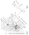
- the locking pin 7 is connected to a coaxial extension 9, which serves as a push rod 10 of the locking pin 7. Between the push rod 10 and a latter movable drive 11 is an actuator 12 - Fig. 3 - Provided, wherein the push rod 10 is movable between a locking position Vst and an unlocking position Est, - Fig.2 -.
- the drive 11 is shown as an electric motor unit 13, and a single control lever 14 essentially forms the actuating device 12.
- the control lever 14 is directly connected to the push rod 10 of the locking pin 7 and to the electric motor unit 13 in operative connection.
- the control lever 14 is of one-armed type and works at one of the push rod 10 facing end 15 with the interposition of a connecting device 16 with the push rod 10 together.
- the connecting device 16 is composed of a receiving fork 17 and a circular section 18 having a bolt portion 19 of the push rod 10.
- the receiving fork 17 surrounds the circular cross section 18 at least partially positively, and it is in Axial direction of the bolt portion 19 of radial spaced-apart stop elements 20 and 21 limited.
- the stop members 20 and / or 21 include e.g. Flange projections or collar.
- the control lever 14 acts on an output 22 - Fig. 3 - The electric motor unit 13 to end facing 23 via a positive connection 24 with said output 22 together.
- An annular region 25 of the control lever 14 surrounds a pin 26.
- the positive connection 24 comprises an internal toothing 27 of the annular portion 25 and an external toothing 28 of the pin 26.
- the internal toothing 27 is incorporated in an actuating sleeve 29 which has a radial stop element 30 adjacent to the electric motor unit 13 and is surrounded by the annular region 25 or is arranged in a bore 31 of the annular region 25.
- a bearing bush 33 is inserted between a shaft 32 of the actuating sleeve 29 and the bore 31 of the annular portion 25 of the control lever 14, a bearing bush 33 is inserted.
- annular, plate-like clamping member 35 For axial securing of the control lever 14 and the annular portion 25 on the pin 26 is an annular, plate-like clamping member 35 and an axial screw 36 which rests with a threaded stem 37 in a thread 38 of the pin 26.
- an inner side 39 of the clamping member 35 is supported at one end 40 of the shaft 32 and a collar 41 on the circumference of the clamping member 35 holds the annular portion 25 in the axial direction, such that the control lever 14 relative to the actuating sleeve 29 -arrow Pf-is relatively movable
- the radial stop element 30 is provided with a ring-shaped recess 42 - Fig. 2 - Which is bounded by a first stop 43 and a second stop 44.
- the recess 42, the stops 43 and 44 and the driver 45 form a kind of freewheel F1, whereby the recess 42 is movable relative to the driver 45, and that when the electric motor unit 13 is effective.
- the pin 26 of the output 22 belongs to a gear 46, and a rotation axis 47 of the pin 26 is arranged transversely to a longitudinal center plane A-A of an electric motor 48 of the electric motor unit 13.
- the pin 26 is integrated into the gear 46, which forms the said electric motor unit 13 with the electric motor 48.
- the longitudinal center plane A-A of the electric motor 48 and a longitudinal center plane B-B of the push rod 10 are substantially parallel to each other.
- control lever 14 for structural reasons between connecting device 16 and positive connection 24 from the annular portion 25 from a cranked lever portion 49, which allows the electric motor 48 to pass past a housing portion 50 of the ball bearing head 3.
- the rotating electric motor 48 overcomes an idle path Lw to compensate for system immanent tolerances or to have an optimized torque of the electric motor 48.
- a normal switching point Schn is reached when the stop 43 acts on the driver 45.
- the push rod 10 is moved with locking pin 7 to the left - Fig. 2 -, And while until the maximum end position Em is reached and the unlocking device 8 is disengaged.
- the ball rod 5 of the trailer coupling 1 passes in the disengaged state of the unlocking device 8 by its own weight in an intermediate position and is from there, for example, manually in the rest position spent. In the rest position, the unlocking device 8 is engaged again as locked and can be unlocked again, if desired.
Landscapes
- Engineering & Computer Science (AREA)
- Transportation (AREA)
- Mechanical Engineering (AREA)
- Lock And Its Accessories (AREA)
- Agricultural Machines (AREA)
Applications Claiming Priority (1)
| Application Number | Priority Date | Filing Date | Title |
|---|---|---|---|
| DE102012011054A DE102012011054A1 (de) | 2012-06-04 | 2012-06-04 | Entriegelungseinrichtung für eine Anhängekupplung eines Kraftfahrzeugs |
Publications (2)
| Publication Number | Publication Date |
|---|---|
| EP2671736A2 true EP2671736A2 (fr) | 2013-12-11 |
| EP2671736A3 EP2671736A3 (fr) | 2015-10-28 |
Family
ID=48534127
Family Applications (1)
| Application Number | Title | Priority Date | Filing Date |
|---|---|---|---|
| EP13002733.7A Withdrawn EP2671736A3 (fr) | 2012-06-04 | 2013-05-27 | Dispositif de déverrouillage pour un attelage de véhicule automobile |
Country Status (2)
| Country | Link |
|---|---|
| EP (1) | EP2671736A3 (fr) |
| DE (1) | DE102012011054A1 (fr) |
Citations (3)
| Publication number | Priority date | Publication date | Assignee | Title |
|---|---|---|---|---|
| DE19902355A1 (de) | 1999-01-21 | 2000-08-03 | Oris Fahrzeugteile Riehle H | Anhängekupplung |
| DE10320302A1 (de) | 2003-05-07 | 2004-12-09 | Westfalia-Automotive Gmbh & Co. Kg | Anhängekupplung für Kraftfahrzeuge |
| EP1614556A1 (fr) | 2004-07-07 | 2006-01-11 | Westfalia Automotive GmbH & Co. KG | Attelage de remorque pour véhicules automobiles |
Family Cites Families (2)
| Publication number | Priority date | Publication date | Assignee | Title |
|---|---|---|---|---|
| DE10144254A1 (de) * | 2001-09-03 | 2003-04-03 | Oris Fahrzeugteile Riehle H | Anhängekupplung |
| DE202005020447U1 (de) * | 2005-11-25 | 2006-02-23 | Jaeger Cartronix Gmbh | Antriebseinheit für eine Anhängerkupplung |
-
2012
- 2012-06-04 DE DE102012011054A patent/DE102012011054A1/de not_active Withdrawn
-
2013
- 2013-05-27 EP EP13002733.7A patent/EP2671736A3/fr not_active Withdrawn
Patent Citations (3)
| Publication number | Priority date | Publication date | Assignee | Title |
|---|---|---|---|---|
| DE19902355A1 (de) | 1999-01-21 | 2000-08-03 | Oris Fahrzeugteile Riehle H | Anhängekupplung |
| DE10320302A1 (de) | 2003-05-07 | 2004-12-09 | Westfalia-Automotive Gmbh & Co. Kg | Anhängekupplung für Kraftfahrzeuge |
| EP1614556A1 (fr) | 2004-07-07 | 2006-01-11 | Westfalia Automotive GmbH & Co. KG | Attelage de remorque pour véhicules automobiles |
Also Published As
| Publication number | Publication date |
|---|---|
| EP2671736A3 (fr) | 2015-10-28 |
| DE102012011054A1 (de) | 2013-12-05 |
Similar Documents
| Publication | Publication Date | Title |
|---|---|---|
| EP1557298B1 (fr) | Attelage de remorque | |
| DE3027282A1 (de) | Differential fuer fahrzeuge mit vierrad-antrieb | |
| EP0373368B1 (fr) | Dispositif pour verrouiller un levier de changement de vitesse dans une position correspondant à un rapport ou d'une programmation de rapports dépendant d'une pédale de frein | |
| EP2332750B1 (fr) | Attelage doté d'un agencement de capteur et d'un corps d'amenée rotatif | |
| EP1952947B1 (fr) | Outil à main motorisé permettant perçage et vissage | |
| DE102019130396A1 (de) | Vorrichtung zum Betätigen einer Parksperre in einem Automatik-Getriebe eines Kraftfahrzeuges | |
| EP1084870B1 (fr) | Dispositif d'attelage articulé à verrouillage automatique | |
| WO2022188912A1 (fr) | Verrou de stationnement dans une configuration verrouillée normale pour dispositif de verrou de stationnement d'une boîte de vitesses | |
| EP2036421B1 (fr) | Dispositif de couplage d'un arbre de transmission avec la prise de force d'un tracteur | |
| DE4210403C2 (de) | Deckelverriegelungsvorrichtung | |
| DE102020122237A1 (de) | Elektromechanischer Parksperrenaktuator | |
| EP3508397B1 (fr) | Dispositif de direction d'un véhicule automobile et transmission intermédiaire correspondante | |
| DE102017218638A1 (de) | Betätigungsanordnung für eine Parksperre für ein Kraftfahrzeug | |
| DE102016224660A1 (de) | Betätigungsanordnung für eine Parksperre für ein Kraftfahrzeug | |
| EP1544003B1 (fr) | Dispositif d'attelage pour véhicules automobiles | |
| EP2859255B1 (fr) | Frein de stationnement pour une boîte de vitesses d'un véhicule automobile | |
| DE19532590B4 (de) | Motor- und handbetätigbarer Stellantrieb | |
| EP0675012A1 (fr) | Dispositif pour déconnecter un attelage de remorque | |
| DE10157460A1 (de) | Anordnung zum Einlegen einer Parksperre eines Fahrzeuges durch einen Elektromotor und ein hilfskraftbetriebenes Notstellglied | |
| EP1790504B2 (fr) | Unité d'entraînement pour un attelage de remorque | |
| EP2671736A2 (fr) | Dispositif de déverrouillage pour un attelage de véhicule automobile | |
| EP1566238B1 (fr) | Système électrique de mouvement linéaire avec un accouplement direct entre un système vis-écrou et un module moteur | |
| DE10151382B4 (de) | Anhängevorrichtung | |
| DE102019109398B4 (de) | Anhängerkupplung | |
| DE10324277B4 (de) | Scheibenwischeranlage |
Legal Events
| Date | Code | Title | Description |
|---|---|---|---|
| PUAI | Public reference made under article 153(3) epc to a published international application that has entered the european phase |
Free format text: ORIGINAL CODE: 0009012 |
|
| AK | Designated contracting states |
Kind code of ref document: A2 Designated state(s): AL AT BE BG CH CY CZ DE DK EE ES FI FR GB GR HR HU IE IS IT LI LT LU LV MC MK MT NL NO PL PT RO RS SE SI SK SM TR |
|
| AX | Request for extension of the european patent |
Extension state: BA ME |
|
| PUAL | Search report despatched |
Free format text: ORIGINAL CODE: 0009013 |
|
| AK | Designated contracting states |
Kind code of ref document: A3 Designated state(s): AL AT BE BG CH CY CZ DE DK EE ES FI FR GB GR HR HU IE IS IT LI LT LU LV MC MK MT NL NO PL PT RO RS SE SI SK SM TR |
|
| AX | Request for extension of the european patent |
Extension state: BA ME |
|
| RIC1 | Information provided on ipc code assigned before grant |
Ipc: B60D 1/52 20060101AFI20150924BHEP Ipc: B60D 1/54 20060101ALI20150924BHEP |
|
| STAA | Information on the status of an ep patent application or granted ep patent |
Free format text: STATUS: THE APPLICATION IS DEEMED TO BE WITHDRAWN |
|
| 18D | Application deemed to be withdrawn |
Effective date: 20160429 |