EP2671776A2 - Chevalet pour une structure de support comprenant une traverse pour un véhicule automobile - Google Patents
Chevalet pour une structure de support comprenant une traverse pour un véhicule automobile Download PDFInfo
- Publication number
- EP2671776A2 EP2671776A2 EP13001384.0A EP13001384A EP2671776A2 EP 2671776 A2 EP2671776 A2 EP 2671776A2 EP 13001384 A EP13001384 A EP 13001384A EP 2671776 A2 EP2671776 A2 EP 2671776A2
- Authority
- EP
- European Patent Office
- Prior art keywords
- cross member
- support
- connecting device
- connecting means
- additional
- Prior art date
- Legal status (The legal status is an assumption and is not a legal conclusion. Google has not performed a legal analysis and makes no representation as to the accuracy of the status listed.)
- Granted
Links
Images




Classifications
-
- B—PERFORMING OPERATIONS; TRANSPORTING
- B62—LAND VEHICLES FOR TRAVELLING OTHERWISE THAN ON RAILS
- B62D—MOTOR VEHICLES; TRAILERS
- B62D21/00—Understructures, i.e. chassis frame on which a vehicle body may be mounted
- B62D21/02—Understructures, i.e. chassis frame on which a vehicle body may be mounted comprising longitudinally or transversely arranged frame members
-
- B—PERFORMING OPERATIONS; TRANSPORTING
- B60—VEHICLES IN GENERAL
- B60G—VEHICLE SUSPENSION ARRANGEMENTS
- B60G7/00—Pivoted suspension arms; Accessories thereof
- B60G7/02—Attaching arms to sprung part of vehicle
-
- B—PERFORMING OPERATIONS; TRANSPORTING
- B62—LAND VEHICLES FOR TRAVELLING OTHERWISE THAN ON RAILS
- B62D—MOTOR VEHICLES; TRAILERS
- B62D21/00—Understructures, i.e. chassis frame on which a vehicle body may be mounted
- B62D21/08—Understructures, i.e. chassis frame on which a vehicle body may be mounted built up with interlaced cross members
-
- B—PERFORMING OPERATIONS; TRANSPORTING
- B62—LAND VEHICLES FOR TRAVELLING OTHERWISE THAN ON RAILS
- B62D—MOTOR VEHICLES; TRAILERS
- B62D21/00—Understructures, i.e. chassis frame on which a vehicle body may be mounted
- B62D21/09—Means for mounting load bearing surfaces
-
- B—PERFORMING OPERATIONS; TRANSPORTING
- B62—LAND VEHICLES FOR TRAVELLING OTHERWISE THAN ON RAILS
- B62D—MOTOR VEHICLES; TRAILERS
- B62D21/00—Understructures, i.e. chassis frame on which a vehicle body may be mounted
- B62D21/11—Understructures, i.e. chassis frame on which a vehicle body may be mounted with resilient means for suspension, e.g. of wheels or engine; sub-frames for mounting engine or suspensions
-
- B—PERFORMING OPERATIONS; TRANSPORTING
- B60—VEHICLES IN GENERAL
- B60G—VEHICLE SUSPENSION ARRANGEMENTS
- B60G2206/00—Indexing codes related to the manufacturing of suspensions: constructional features, the materials used, procedures or tools
- B60G2206/01—Constructional features of suspension elements, e.g. arms, dampers, springs
- B60G2206/60—Subframe construction
- B60G2206/601—Hanger bracket
-
- B—PERFORMING OPERATIONS; TRANSPORTING
- B60—VEHICLES IN GENERAL
- B60G—VEHICLE SUSPENSION ARRANGEMENTS
- B60G2300/00—Indexing codes relating to the type of vehicle
- B60G2300/02—Trucks; Load vehicles
Definitions
- the invention relates to a support bracket for a cross member comprehensive support structure for a motor vehicle and a support structure with such a support bracket.
- Support brackets such as trailing arm blocks for commercial vehicles such as trucks or buses are essentially the forwarding of chassis forces in the chassis structure.
- a multi-functional bearing block is known, which has side walls which are arranged at an angle to each other and at least partially surround insert walls for stiffening the multi-function bearing block, which run at an angle to the longitudinal axis of the multi-functional bearing block.
- the multifunction bearing block works well in itself, its manufacture is complex and always requires the production of two different multifunction bearing blocks, namely one which is designed to be mounted on one side of a cross member (eg left) and another multifunction bearing block which is formed to be attached to the other side of the cross member (eg right).
- An object of the invention is to provide an improved and / or alternative support for a utility vehicle, such as a truck. to create a bus or a truck.
- the support bracket according to the invention for a support structure comprising a cross member for a motor vehicle, in particular commercial vehicle (for example bus or truck), is provided with a connecting device for the cross member and is designed so that it can be used on both sides of the cross member.
- a connecting device for the cross member for example bus or truck
- the support bracket according to the invention can be used with respect to the cross member expedient both left and right.
- at least approximately identical support brackets can be used on the cross member, resulting in e.g. Cost savings (for example, in terms of manufacturing costs, machine costs, tooling costs, administrative costs, etc.), but also a reduction of item numbers is made possible.
- the support bracket is at least so nearly symmetrical relative to a plane of symmetry to be used with respect to the cross member on both sides.
- the support bracket preferably comprises a plurality of connecting means by means of which the parts to be joined can be mounted on the support bracket.
- the support bracket comprises e.g. a connecting device for a trailing arm device, a connecting device for a longitudinal member, a connecting device for a Spantkonstrutation (eg a suitably parallel to the cross member extending carrier, eg a U-profile carrier), a connecting device for at least one additional cross member, a connecting device for a Steering device, in particular a triangular link device, and / or at least one connecting device for at least one additional functional part, preferably a braking device and / or an additional strut for reinforcing the supporting structure.
- a connecting device for a trailing arm device e.g. a connecting device for a trailing arm device, a connecting device for a longitudinal member, a connecting device for a Spantkonstrukom (eg a suitably parallel to the cross member extending carrier, eg a U-profile carrier
- the connecting device for the former construction defines the plane of symmetry.
- the connecting device for the cross member may for example be laterally spaced from the plane of symmetry.
- the connecting means for the trailing arm means may e.g. extend substantially transverse to the plane of symmetry.
- the connecting means for the side member may e.g. be formed as a mounting surface which extends substantially transverse to the plane of symmetry.
- the connecting device for at least one additional cross member is preferably laterally spaced from the plane of symmetry.
- the support bracket may comprise at least one connecting device, which is designed as a flange construction, which expediently protrudes from the main body of the supporting block, e.g. substantially perpendicular, and / or extending substantially parallel to the side rail.
- the support bracket has at least one connecting device, which comprises at least one fastening surface, which is aligned at least approximately at right angles to the longitudinal extension of the cross member, in particular at least approximately parallel to the longitudinal extension of the longitudinal member.
- the at least one attachment surface preferably extends at least approximately vertically. This preferably applies to the longitudinal beam connecting device and / or the additional cross beam connecting device, e.g. protrude to the same side of the support block and / or can extend substantially parallel to each other.
- At least one connecting device comprises an opening into which the element to be connected is inserted or through which the element to be connected is feasible.
- the support bracket comprises a passage or insertion opening which is formed for the additional cross member.
- the connecting device for the former construction can e.g. have two height moderately spaced flange means, whereby suitably tensile and compressive forces are defined episodleitbar.
- the connecting device for the cross member and / or the connecting device for the at least one additional cross member preferably comprises two relative to the plane of symmetry laterally spaced flange.
- the connecting device for the cross member and the connecting device for the former construction extend in different directions, preferably in opposite directions.
- the connecting device for the longitudinal member is preferably designed as a fastening surface which extends substantially at right angles to the connecting means for the cross member, the connecting means for the former construction and / or the connecting means for the additional cross member.
- the connecting device for the cross member and the connecting means for the additional cross member are preferably on the same side of the support bracket and / or are arranged in a plane that the cross member and the additional cross member can be made the same width or even identical.
- the connecting means for the cross member and the connecting means for the additional functional part are arranged in a plane.
- the connecting means for the cross member and the connecting means for the additional functional part are laterally spaced from each other, preferably so that after tying the cross member to the connecting means, the surface of the cross member and the surface of the connecting means for the additional Function part form a plane.
- this level may be appropriate another Holding device or generally another functional element to be fixed and that advantageously without spacers or other balancing pieces must be used.
- the connecting device for the cross member is preferably arranged lower than the connecting device for the former construction and / or the connecting device for the longitudinal member. This preferably makes it possible that the cross member may extend below the level of the former construction and / or below the level of the longitudinal member.
- the connecting device for the additional cross member is preferably arranged lower than the connecting device for the cross member.
- the main body of the support frame is preferably defined by a web portion and a preferably substantially transversely extending flange portion.
- the web portion and the flange portion form a substantially T-shaped configuration.
- the invention includes not only a support bracket but also a support structure, in particular frame or steering construction, for a motor vehicle, preferably a utility vehicle (e.g., a bus or a lorry).
- the support structure comprises two support brackets, which are arranged on both sides of a cross member.
- the support brackets can be designed as described herein and are therefore designed in particular at least almost identical.
- the support structure according to the invention is thus characterized in particular by the fact that a support bracket of identical design is used both on one side of the cross member (for example on the left) and on the other side of the cross member (for example on the right).
- the support structure expediently comprises side members and / or bulkhead constructions connected to the support brackets, the crossbeam preferably being below the level of the longitudinal members and / or below the level of the frame structures, whereby a height offset is generated.
- the frame constructions are e.g. Expediently parallel to the cross member extending carrier, e.g. U-section beam.
- the support structure preferably has two support means, which are arranged between the cross member and the side members and / or the bulkhead structures and / or which are arranged at least partially within the height offset, e.g. to stiffen the support brackets and / or to at least reduce or smooth a sudden force flow which would occur without the support means by the height offset, whereby a gentler Kraftcheniquess Sung is expediently feasible.
- the support means are preferably additionally used as support brackets for a steering device, in particular triangular link device.
- At least the main body of the support bracket and / or at least the main body of the support device is designed as a casting.
- these castings e.g. additional holding devices are mounted, e.g. riveted, screwed and / or welded.
- the side members and / or the bulkhead constructions may suitably comprise conventional supporting profiles, preferably U-profiles.
- the cross member is preferably a U-profile, a T-profile, a double-T or I-profile, e.g. with varying height.
- the track block does not have to be completely symmetrical relative to the plane of symmetry and / or the support blocks do not have to be made completely identical on the two sides of the cross member. It is appropriate that they are the same. Post-processing, manufacturing tolerances, subsequent assembly, attachments, etc. are also included by the invention.
- the elements to be connected to the support frame are preferably fastened directly to the support frame, but embodiments are also possible in which they are over additional spacers are indirectly connected to the support bracket.
- the support bracket is preferably a trailing arm block.
- connection technique between the elements to be connected e.g. Screw, rivet and / or welded joints can be used, but also any other suitable fastening techniques.
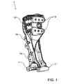
- FIG. 1-3 show different views of a support bracket 1 according to an embodiment of the invention.
- the support frame 1 is for use in an example in FIG. 4 shown support structure for a commercial vehicle provided.
- the support bracket 1 is configured to be connected by means of a connecting device 10 with a cross member 20.
- the support frame 1 further comprises a connecting device 11 for a trailing arm device 21, via which the trailing arm device can be mounted on the support frame 1.
- the support frame 1 also comprises a connection device 12 for a longitudinal member 22, via which the longitudinal member 22 can be mounted on the support frame 1.
- the support frame 1 also comprises a connecting device 13 for a former construction 23 (eg a U-profile support), via which the former construction 23 can be mounted on the support frame 1.
- the support frame 1 comprises a connecting device 14 for an additional cross member 24, via which the cross member 24 can be mounted on the support frame 1.
- the support bracket 1 may also have one or more additional connection means, eg for a wishbone, a brake device, an additional strut to reinforce the support structure, etc ..
- the support bracket 1 is designed to be substantially symmetrical relative to a plane of symmetry SE, suitably at least so symmetrical that it is on both sides LS1 and LS2 of the cross member 20 is used so appropriate left and right with respect to the cross member 20.
- the cross member 20 can be equipped with two identical support brackets 1.
- the plane of symmetry SE is defined by the connecting device 13 for the former construction 23, which extends along the center of the support frame 1.
- the connecting device 10 for the cross member 20 is laterally spaced from the plane of symmetry SE, while the connecting device 11 for the trailing arm device 21 extends substantially transversely to the plane of symmetry SE.
- the connecting device 12 for the longitudinal member 22 is designed as a fastening surface, which extends substantially transversely to the plane of symmetry SE.
- the connecting device 14 for the additional cross member 24 is similar to the connecting device 10 for the cross member 20 laterally spaced from the plane of symmetry SE.
- the connecting device 10 for the cross member 20 and the connecting means 14 for the additional cross member 24 are designed as a pair of flanges, with a flange on one side of the plane of symmetry SE and another flange on the other side of the symmetry plane SE.
- the connecting device 13 for the former construction 23 has two height-wise spaced apart flange means, whereby tensile and compressive forces can be defined recorded and forwarded.
- the connecting device 10 for the cross member 20 and the connecting device 13 for the former construction 23 extend in opposite directions, while the connecting device 12 designed as a fastening surface for the longitudinal member 22 extends substantially at right angles to the connecting device 10 for the cross member 20, the connecting device 13 for the Spantkonstrutation 23 and the connecting means 14 for the additional cross member 24.
- the connecting means 10 for the cross member 20 and the connecting means 14 for the additional cross member 24 are to the same side of the support block 1 from.
- the connecting device 10 for the cross member 20 is arranged lower than the connecting device 13 for the former construction 23 and the connecting device 12 for the longitudinal member 22, thereby allowing the cross member 20 below the level of the frame construction 23 and below the level of the longitudinal member 22 extends.
- the connecting device 14 for the additional cross member 24 in turn is arranged lower than the connecting device 10 for the cross member 20, thereby allowing the additional cross member 24 extends below the level of the cross member 20 and thereby substantially strengthen the support frame 1 or generally the support structure.
- the main body of the support bracket 1 is with reference to the FIG. 2 defined by a web portion SA and a substantially transverse thereto flange portion FA, whereby a substantially T-shaped configuration is formed.
- the transition between the web portion SA and the flange portion FA may be carried out in the classical T-shaped or flowing in the context of the invention.
- the main body of the support bracket 1 or generally the support frame 1 is designed as a casting, but in the context of the invention, but additional elements may be mounted, for. by screw, rivet or welded joints.
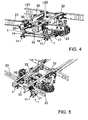
- the Figures 4-7 show various views of a support structure for a commercial vehicle according to an embodiment of the invention.
- the support structure is designed as a frame or steering construction, in particular trailing arm construction, for the commercial vehicle.
- the support structure comprises the cross member 20.
- Reference symbol LS1 denotes the one side of the cross member 20 (in FIG. 4 eg the left side) and LS2 marks the other side of the cross member 20 (in FIG. 4 eg the right side).
- the cross member 20 comprises at its Both sides LS1 and LS2 each have a similar support bracket 1, according to the Figures 1-3 can be executed.
- the support structure also includes trailing arms 21, which are connected via the connecting means 11 with the support brackets 1.
- the support structure includes side members 22, which are connected via the connecting means 12 with the support brackets 1.
- the support structure includes bulkhead structures 23, which are connected via the connecting means 13 with the support brackets 1.
- the support structure comprises an additional cross member 24, which is connected via the connecting means 14 with the support brackets 1.
- the frame structures 23 and the cross member 20 extend parallel and preferably form together with the additional cross member 24 a cross member association, while the side members 22 extend transversely thereto.
- the longitudinal members 22, the Spantkonstrukomen 23 and the additional cross member 24 are designed as U-profiles, while the cross member 20 is designed as a T-profile with preferably varying height.
- the cross member 20 may also be e.g. be designed as U-profile, T or double T-profile.
- the cross member 20 extends below the level of the longitudinal members 22 and below the level of the frame structures 23 that a height offset HV (see FIG. 6 ) is produced.
- HV height offset
- support means 50 are arranged, which stiffen the support brackets 1 and additionally serve as support brackets for a triangular link device 25.
- the support means 50 are arranged between the level of the upper edge of the cross member 20 and the level of the upper edge (s) of the side members 22 and the Spantkonstrutationen 23.
- FIG. 8 shows a frontal view of a part of the in the FIGS. 4 to 7 shown supporting structure.
- the floor F of the commercial vehicle is schematically indicated.
- the support means 50 are each spaced by means of a gap ZR sections of the cross member 20.
- FIG. 8 schematically a force flow principle KF, which is realized by the support structure.
- the support brackets 1 are stiffened.
- a tragwerkstechnisch unfavorable, erratic force flow KF ' as in FIG. 9 shown schematically, which would occur without the support means 50, at least reduced and smoothed, whereby a gentler power flow change can be realized.
- voltage peaks can be minimized.
- the support means 50 thus support the abrupt kink and allow a tragwerkstechnisch improved, especially gentle change in force flow.
- FIG. 10 shows an exploded frontal view of the previously described embodiment of the Figures 4-8 , It can sometimes be seen that the support means 50 each have a mounting surface 51 to be attached to the side members 22, in particular its web portions, and a mounting surface 52 to be attached to the cross member 20, in particular its flange portion. It should be mentioned that the support means 50 can be attached to the web and / or flange portions of the cross member 20.
- FIG. 11 shows a frontal view of a support structure according to another embodiment of the invention.
- a peculiarity of this support structure is that it comprises additional braces 26 for their reinforcement, which can be connected on the one hand via the connecting means 16 with the support blocks 1 and on the other hand with the bulkhead structures 23 and / or the commercial vehicle structure (eg a side wall or a side pillar thereof).
- the additional cross member 24 is guided by the support brackets 1 or on the support brackets 1 in one piece, to be connected to the commercial vehicle body, and thus expediently takes over the function of the additional struts 26.
- the additional struts 26 can, as in FIG. 11 to see, parallel or obliquely to the cross member 20 and the Spantkonstrutationen 23 run.
- FIG. 12 shows a perspective view of a support bracket 1 according to yet another embodiment of the invention.
- a special feature of this support bracket 1 is a passage opening ⁇ , through which an additional cross member 24 can be passed through the support frame 1 to be connected to the commercial vehicle body and / or the support frame 1.
- FIG. 13 shows a frontal view of a support structure and trusses 1 according to yet another embodiment of the invention.
- a special feature of this embodiment is that the connecting device 10 are arranged for the cross member 20 and the connecting means 14 for the additional cross member 24 in a plane E1, that the cross member 10 and the additional cross member 24 can be made the same width or even identical.
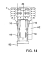
- FIG. 14 shows a side view of a support structure with a support bracket 1 according to another embodiment of the invention.
- a special feature of this embodiment is that the connecting device 10 for the cross member 20 and the connecting means 16 for the additional functional part are laterally spaced apart such that after mounting the cross member 20 to the connecting device 10, the surface of the cross member 20 and the surface of the connecting device 16 a Form level E2. It is advantageous that on the plane E2, for example, a further holding device or another suitable functional part HE can be attached without having to use spacers.
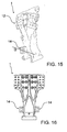
- FIG. 15 shows a perspective view of yet another support frame 1 according to an embodiment of the invention, while FIG. 16 a side view of the support bracket 1 from FIG. 15 shows.
- connection means 14 which are designed as a flange construction (eg flange means) and each having at least one mounting surface, which is vertical extends and which has in the transverse direction Q, whereby it is aligned substantially parallel to the longitudinal extension of the longitudinal member 22 and / or substantially perpendicular to the longitudinal extent of the cross member 20.
Landscapes
- Engineering & Computer Science (AREA)
- Mechanical Engineering (AREA)
- Chemical & Material Sciences (AREA)
- Combustion & Propulsion (AREA)
- Transportation (AREA)
- Body Structure For Vehicles (AREA)
Applications Claiming Priority (1)
| Application Number | Priority Date | Filing Date | Title |
|---|---|---|---|
| DE102012011416A DE102012011416A1 (de) | 2012-06-08 | 2012-06-08 | Tragbock für eine einen Querträger umfassende Tragkonstruktion für ein Kraftfahrzeug |
Publications (3)
| Publication Number | Publication Date |
|---|---|
| EP2671776A2 true EP2671776A2 (fr) | 2013-12-11 |
| EP2671776A3 EP2671776A3 (fr) | 2018-04-25 |
| EP2671776B1 EP2671776B1 (fr) | 2020-11-11 |
Family
ID=47915409
Family Applications (1)
| Application Number | Title | Priority Date | Filing Date |
|---|---|---|---|
| EP13001384.0A Active EP2671776B1 (fr) | 2012-06-08 | 2013-03-18 | Chevalet pour une structure de support comprenant une traverse pour un véhicule automobile |
Country Status (6)
| Country | Link |
|---|---|
| EP (1) | EP2671776B1 (fr) |
| CN (2) | CN108674485B (fr) |
| BR (1) | BR102013012906B1 (fr) |
| DE (1) | DE102012011416A1 (fr) |
| MX (1) | MX376855B (fr) |
| RU (1) | RU2627921C2 (fr) |
Families Citing this family (2)
| Publication number | Priority date | Publication date | Assignee | Title |
|---|---|---|---|---|
| SE538895C2 (sv) | 2014-06-09 | 2017-01-31 | Scania Cv Ab | Förbindelseenhet avsedd att förbinda två luftbälgar i ett fordon |
| JP6510901B2 (ja) * | 2015-06-15 | 2019-05-08 | 日野自動車株式会社 | サスペンション用ブラケット |
Citations (1)
| Publication number | Priority date | Publication date | Assignee | Title |
|---|---|---|---|---|
| DE102008045008A1 (de) | 2008-08-29 | 2010-03-04 | Man Nutzfahrzeuge Aktiengesellschaft | Modularer Multifunktionslagerbock |
Family Cites Families (11)
| Publication number | Priority date | Publication date | Assignee | Title |
|---|---|---|---|---|
| DE19809209A1 (de) * | 1998-03-04 | 1999-09-09 | Man Nutzfahrzeuge Ag | Fahrgestell eines Frontlenker-Lastkraftwagen |
| DE19961669A1 (de) * | 1999-12-21 | 2001-06-28 | Man Nutzfahrzeuge Ag | Längslenkerbock in Nutzfahrzeugen |
| DE102004063939A1 (de) * | 2004-09-17 | 2006-04-20 | MAN Nutzfahrzeuge Österreich AG | Nutzfahrzeug, insbesondere Müllsammel- oder sonstiges Kommunalfahrzeug, mit einem Low-Entry-Fahrerhaus |
| US7857348B2 (en) * | 2006-06-08 | 2010-12-28 | Metalsa Servicios S De Rl | Multi-function cross members for truck frames |
| EP2125495A1 (fr) * | 2006-12-26 | 2009-12-02 | Renault Trucks | Cadre de châssis convenant en particulier à un véhicule lourd |
| US8342565B2 (en) * | 2008-08-27 | 2013-01-01 | Hino Motors, Ltd. | Cross member-integrated trunnion bracket |
| DE102009019787A1 (de) * | 2009-05-02 | 2010-11-04 | Man Nutzfahrzeuge Ag | Trägeranordnung für einen Fahrzeugrahmen eines Nutzfahrzeuges |
| DE102009033826B4 (de) * | 2009-07-18 | 2016-06-30 | Man Truck & Bus Ag | Trägerprofil eines Fahrgestellrahmens |
| CN102219028B (zh) * | 2010-04-16 | 2015-12-16 | 标致·雪铁龙汽车公司 | 包括带垂直开口的两个悬挂臂的用于汽车的后桥 |
| TW201210794A (en) * | 2010-09-14 | 2012-03-16 | Chang Chun Entpr Co Ltd | Fabric curtain blind forming machine |
| NL2005663C2 (en) * | 2010-11-10 | 2012-05-14 | Daf Trucks Nv | Mounting arrangement for a trailer coupling. |
-
2012
- 2012-06-08 DE DE102012011416A patent/DE102012011416A1/de not_active Ceased
-
2013
- 2013-03-18 EP EP13001384.0A patent/EP2671776B1/fr active Active
- 2013-05-24 BR BR102013012906-2A patent/BR102013012906B1/pt active IP Right Grant
- 2013-06-07 MX MX2013006479A patent/MX376855B/es active IP Right Grant
- 2013-06-07 RU RU2013126412A patent/RU2627921C2/ru active
- 2013-06-13 CN CN201810414652.8A patent/CN108674485B/zh active Active
- 2013-06-13 CN CN201310231775.5A patent/CN103481948B/zh active Active
Patent Citations (1)
| Publication number | Priority date | Publication date | Assignee | Title |
|---|---|---|---|---|
| DE102008045008A1 (de) | 2008-08-29 | 2010-03-04 | Man Nutzfahrzeuge Aktiengesellschaft | Modularer Multifunktionslagerbock |
Also Published As
| Publication number | Publication date |
|---|---|
| MX376855B (es) | 2025-03-07 |
| CN108674485A (zh) | 2018-10-19 |
| RU2627921C2 (ru) | 2017-08-14 |
| EP2671776A3 (fr) | 2018-04-25 |
| RU2013126412A (ru) | 2014-12-20 |
| BR102013012906A2 (pt) | 2015-06-09 |
| MX2013006479A (es) | 2014-04-24 |
| BR102013012906B1 (pt) | 2021-12-21 |
| CN108674485B (zh) | 2022-01-14 |
| CN103481948B (zh) | 2018-05-25 |
| CN103481948A (zh) | 2014-01-01 |
| EP2671776B1 (fr) | 2020-11-11 |
| DE102012011416A1 (de) | 2013-12-12 |
Similar Documents
| Publication | Publication Date | Title |
|---|---|---|
| DE102011051481B4 (de) | Stoßfängeranordnung für ein Kraftfahrzeug | |
| EP2394834B1 (fr) | Support de collision de porte | |
| DE102011056737A1 (de) | Vorderwagenstruktur eines Kraftfahrzeugs | |
| DE102013013325A1 (de) | Hilfsrahmen für ein Kraftfahrzeug | |
| DE102008010553A1 (de) | Hilfsrahmen für eine Vorderachse eines Kraftfahrzeugs | |
| EP3630573B1 (fr) | Châssis pour un chariot à plate-forme | |
| DE102009041771A1 (de) | Hilfsrahmen für ein Kraftfahrzeug | |
| WO2009100992A1 (fr) | Traverse de train de roulement pour un véhicule sur rails | |
| DE102009050495A1 (de) | Hilfsrahmen | |
| EP2508407B1 (fr) | Structure, en particulier pour les installations électriques dans un véhicule sur rail, et procédé de fabrication de cette structure | |
| EP2114753B1 (fr) | Support d'essieu pour véhicules automobiles | |
| EP3696056B1 (fr) | Module de châssis de véhicule pourvu d'essieu de véhicule et de noeud de raccordement | |
| DE102016201815A1 (de) | Hilfsrahmen für ein Kraftfahrzeug | |
| DE202014103332U1 (de) | Bodenbaugruppe für Fahrzeuge und Fahrzeug mit einer solchen Bodenbaugruppe | |
| WO2014016049A1 (fr) | Partie antérieure de train | |
| DE102006009189B3 (de) | Befestigungsanordnung von Außenanbauteilen an einem Tragrahmen eines Lastkraftwagens | |
| EP2360081A1 (fr) | Montage de carrosserie de véhicule dans la zone entre les éléments de réception de jambe de suspension et le support transversal de vitre ainsi que procédé de fabrication associé | |
| DE102011001861A1 (de) | Tragstruktur für ein Kraftfahrzeug | |
| DE102012213019B4 (de) | Zugkopfteil | |
| EP3472029A1 (fr) | Système de châssis et véhicule terrestre | |
| EP3339107B1 (fr) | Protection contre l'encastrement à l'arrière pour un véhicule | |
| EP2671776B1 (fr) | Chevalet pour une structure de support comprenant une traverse pour un véhicule automobile | |
| DE102011116155A1 (de) | Hilfsrahmen für Kraftfahrzeuge | |
| DE634467C (de) | Fahrgestellrahmen, insbesondere fuer Kraftfahrzeuge | |
| EP3693252A1 (fr) | Structure porteuse de cadre pourvue de sections porteuses courbées vers le haut |
Legal Events
| Date | Code | Title | Description |
|---|---|---|---|
| PUAI | Public reference made under article 153(3) epc to a published international application that has entered the european phase |
Free format text: ORIGINAL CODE: 0009012 |
|
| AK | Designated contracting states |
Kind code of ref document: A2 Designated state(s): AL AT BE BG CH CY CZ DE DK EE ES FI FR GB GR HR HU IE IS IT LI LT LU LV MC MK MT NL NO PL PT RO RS SE SI SK SM TR |
|
| AX | Request for extension of the european patent |
Extension state: BA ME |
|
| PUAL | Search report despatched |
Free format text: ORIGINAL CODE: 0009013 |
|
| AK | Designated contracting states |
Kind code of ref document: A3 Designated state(s): AL AT BE BG CH CY CZ DE DK EE ES FI FR GB GR HR HU IE IS IT LI LT LU LV MC MK MT NL NO PL PT RO RS SE SI SK SM TR |
|
| AX | Request for extension of the european patent |
Extension state: BA ME |
|
| RIC1 | Information provided on ipc code assigned before grant |
Ipc: B60G 7/02 20060101ALI20180320BHEP Ipc: B62D 21/02 20060101ALI20180320BHEP Ipc: B62D 21/11 20060101AFI20180320BHEP Ipc: B62D 21/09 20060101ALI20180320BHEP |
|
| STAA | Information on the status of an ep patent application or granted ep patent |
Free format text: STATUS: REQUEST FOR EXAMINATION WAS MADE |
|
| 17P | Request for examination filed |
Effective date: 20180926 |
|
| STAA | Information on the status of an ep patent application or granted ep patent |
Free format text: STATUS: EXAMINATION IS IN PROGRESS |
|
| 17Q | First examination report despatched |
Effective date: 20190529 |
|
| RAP1 | Party data changed (applicant data changed or rights of an application transferred) |
Owner name: MAN TRUCK & BUS SE |
|
| GRAP | Despatch of communication of intention to grant a patent |
Free format text: ORIGINAL CODE: EPIDOSNIGR1 |
|
| STAA | Information on the status of an ep patent application or granted ep patent |
Free format text: STATUS: GRANT OF PATENT IS INTENDED |
|
| INTG | Intention to grant announced |
Effective date: 20200625 |
|
| GRAS | Grant fee paid |
Free format text: ORIGINAL CODE: EPIDOSNIGR3 |
|
| GRAA | (expected) grant |
Free format text: ORIGINAL CODE: 0009210 |
|
| STAA | Information on the status of an ep patent application or granted ep patent |
Free format text: STATUS: THE PATENT HAS BEEN GRANTED |
|
| AK | Designated contracting states |
Kind code of ref document: B1 Designated state(s): AL AT BE BG CH CY CZ DE DK EE ES FI FR GB GR HR HU IE IS IT LI LT LU LV MC MK MT NL NO PL PT RO RS SE SI SK SM TR |
|
| REG | Reference to a national code |
Ref country code: GB Ref legal event code: FG4D Free format text: NOT ENGLISH |
|
| REG | Reference to a national code |
Ref country code: CH Ref legal event code: EP |
|
| REG | Reference to a national code |
Ref country code: AT Ref legal event code: REF Ref document number: 1333200 Country of ref document: AT Kind code of ref document: T Effective date: 20201115 |
|
| REG | Reference to a national code |
Ref country code: DE Ref legal event code: R096 Ref document number: 502013015277 Country of ref document: DE |
|
| REG | Reference to a national code |
Ref country code: IE Ref legal event code: FG4D Free format text: LANGUAGE OF EP DOCUMENT: GERMAN |
|
| REG | Reference to a national code |
Ref country code: NL Ref legal event code: FP |
|
| REG | Reference to a national code |
Ref country code: SE Ref legal event code: TRGR |
|
| PG25 | Lapsed in a contracting state [announced via postgrant information from national office to epo] |
Ref country code: RS Free format text: LAPSE BECAUSE OF FAILURE TO SUBMIT A TRANSLATION OF THE DESCRIPTION OR TO PAY THE FEE WITHIN THE PRESCRIBED TIME-LIMIT Effective date: 20201111 Ref country code: FI Free format text: LAPSE BECAUSE OF FAILURE TO SUBMIT A TRANSLATION OF THE DESCRIPTION OR TO PAY THE FEE WITHIN THE PRESCRIBED TIME-LIMIT Effective date: 20201111 Ref country code: NO Free format text: LAPSE BECAUSE OF FAILURE TO SUBMIT A TRANSLATION OF THE DESCRIPTION OR TO PAY THE FEE WITHIN THE PRESCRIBED TIME-LIMIT Effective date: 20210211 Ref country code: PT Free format text: LAPSE BECAUSE OF FAILURE TO SUBMIT A TRANSLATION OF THE DESCRIPTION OR TO PAY THE FEE WITHIN THE PRESCRIBED TIME-LIMIT Effective date: 20210311 Ref country code: GR Free format text: LAPSE BECAUSE OF FAILURE TO SUBMIT A TRANSLATION OF THE DESCRIPTION OR TO PAY THE FEE WITHIN THE PRESCRIBED TIME-LIMIT Effective date: 20210212 |
|
| PG25 | Lapsed in a contracting state [announced via postgrant information from national office to epo] |
Ref country code: BG Free format text: LAPSE BECAUSE OF FAILURE TO SUBMIT A TRANSLATION OF THE DESCRIPTION OR TO PAY THE FEE WITHIN THE PRESCRIBED TIME-LIMIT Effective date: 20210211 Ref country code: LV Free format text: LAPSE BECAUSE OF FAILURE TO SUBMIT A TRANSLATION OF THE DESCRIPTION OR TO PAY THE FEE WITHIN THE PRESCRIBED TIME-LIMIT Effective date: 20201111 Ref country code: IS Free format text: LAPSE BECAUSE OF FAILURE TO SUBMIT A TRANSLATION OF THE DESCRIPTION OR TO PAY THE FEE WITHIN THE PRESCRIBED TIME-LIMIT Effective date: 20210311 Ref country code: PL Free format text: LAPSE BECAUSE OF FAILURE TO SUBMIT A TRANSLATION OF THE DESCRIPTION OR TO PAY THE FEE WITHIN THE PRESCRIBED TIME-LIMIT Effective date: 20201111 |
|
| REG | Reference to a national code |
Ref country code: LT Ref legal event code: MG9D |
|
| PG25 | Lapsed in a contracting state [announced via postgrant information from national office to epo] |
Ref country code: HR Free format text: LAPSE BECAUSE OF FAILURE TO SUBMIT A TRANSLATION OF THE DESCRIPTION OR TO PAY THE FEE WITHIN THE PRESCRIBED TIME-LIMIT Effective date: 20201111 |
|
| PG25 | Lapsed in a contracting state [announced via postgrant information from national office to epo] |
Ref country code: RO Free format text: LAPSE BECAUSE OF FAILURE TO SUBMIT A TRANSLATION OF THE DESCRIPTION OR TO PAY THE FEE WITHIN THE PRESCRIBED TIME-LIMIT Effective date: 20201111 Ref country code: SK Free format text: LAPSE BECAUSE OF FAILURE TO SUBMIT A TRANSLATION OF THE DESCRIPTION OR TO PAY THE FEE WITHIN THE PRESCRIBED TIME-LIMIT Effective date: 20201111 Ref country code: LT Free format text: LAPSE BECAUSE OF FAILURE TO SUBMIT A TRANSLATION OF THE DESCRIPTION OR TO PAY THE FEE WITHIN THE PRESCRIBED TIME-LIMIT Effective date: 20201111 Ref country code: EE Free format text: LAPSE BECAUSE OF FAILURE TO SUBMIT A TRANSLATION OF THE DESCRIPTION OR TO PAY THE FEE WITHIN THE PRESCRIBED TIME-LIMIT Effective date: 20201111 Ref country code: CZ Free format text: LAPSE BECAUSE OF FAILURE TO SUBMIT A TRANSLATION OF THE DESCRIPTION OR TO PAY THE FEE WITHIN THE PRESCRIBED TIME-LIMIT Effective date: 20201111 Ref country code: SM Free format text: LAPSE BECAUSE OF FAILURE TO SUBMIT A TRANSLATION OF THE DESCRIPTION OR TO PAY THE FEE WITHIN THE PRESCRIBED TIME-LIMIT Effective date: 20201111 |
|
| REG | Reference to a national code |
Ref country code: DE Ref legal event code: R097 Ref document number: 502013015277 Country of ref document: DE |
|
| PG25 | Lapsed in a contracting state [announced via postgrant information from national office to epo] |
Ref country code: DK Free format text: LAPSE BECAUSE OF FAILURE TO SUBMIT A TRANSLATION OF THE DESCRIPTION OR TO PAY THE FEE WITHIN THE PRESCRIBED TIME-LIMIT Effective date: 20201111 |
|
| PLBE | No opposition filed within time limit |
Free format text: ORIGINAL CODE: 0009261 |
|
| STAA | Information on the status of an ep patent application or granted ep patent |
Free format text: STATUS: NO OPPOSITION FILED WITHIN TIME LIMIT |
|
| 26N | No opposition filed |
Effective date: 20210812 |
|
| PG25 | Lapsed in a contracting state [announced via postgrant information from national office to epo] |
Ref country code: MC Free format text: LAPSE BECAUSE OF FAILURE TO SUBMIT A TRANSLATION OF THE DESCRIPTION OR TO PAY THE FEE WITHIN THE PRESCRIBED TIME-LIMIT Effective date: 20201111 Ref country code: AL Free format text: LAPSE BECAUSE OF FAILURE TO SUBMIT A TRANSLATION OF THE DESCRIPTION OR TO PAY THE FEE WITHIN THE PRESCRIBED TIME-LIMIT Effective date: 20201111 |
|
| REG | Reference to a national code |
Ref country code: CH Ref legal event code: PL |
|
| GBPC | Gb: european patent ceased through non-payment of renewal fee |
Effective date: 20210318 |
|
| PG25 | Lapsed in a contracting state [announced via postgrant information from national office to epo] |
Ref country code: SI Free format text: LAPSE BECAUSE OF FAILURE TO SUBMIT A TRANSLATION OF THE DESCRIPTION OR TO PAY THE FEE WITHIN THE PRESCRIBED TIME-LIMIT Effective date: 20201111 Ref country code: ES Free format text: LAPSE BECAUSE OF FAILURE TO SUBMIT A TRANSLATION OF THE DESCRIPTION OR TO PAY THE FEE WITHIN THE PRESCRIBED TIME-LIMIT Effective date: 20201111 |
|
| REG | Reference to a national code |
Ref country code: BE Ref legal event code: MM Effective date: 20210331 |
|
| PG25 | Lapsed in a contracting state [announced via postgrant information from national office to epo] |
Ref country code: CH Free format text: LAPSE BECAUSE OF NON-PAYMENT OF DUE FEES Effective date: 20210331 Ref country code: LU Free format text: LAPSE BECAUSE OF NON-PAYMENT OF DUE FEES Effective date: 20210318 Ref country code: LI Free format text: LAPSE BECAUSE OF NON-PAYMENT OF DUE FEES Effective date: 20210331 Ref country code: IE Free format text: LAPSE BECAUSE OF NON-PAYMENT OF DUE FEES Effective date: 20210318 Ref country code: GB Free format text: LAPSE BECAUSE OF NON-PAYMENT OF DUE FEES Effective date: 20210318 |
|
| REG | Reference to a national code |
Ref country code: AT Ref legal event code: MM01 Ref document number: 1333200 Country of ref document: AT Kind code of ref document: T Effective date: 20210318 |
|
| PG25 | Lapsed in a contracting state [announced via postgrant information from national office to epo] |
Ref country code: IS Free format text: LAPSE BECAUSE OF FAILURE TO SUBMIT A TRANSLATION OF THE DESCRIPTION OR TO PAY THE FEE WITHIN THE PRESCRIBED TIME-LIMIT Effective date: 20210311 |
|
| PG25 | Lapsed in a contracting state [announced via postgrant information from national office to epo] |
Ref country code: BE Free format text: LAPSE BECAUSE OF NON-PAYMENT OF DUE FEES Effective date: 20210331 |
|
| PG25 | Lapsed in a contracting state [announced via postgrant information from national office to epo] |
Ref country code: AT Free format text: LAPSE BECAUSE OF NON-PAYMENT OF DUE FEES Effective date: 20210318 |
|
| PG25 | Lapsed in a contracting state [announced via postgrant information from national office to epo] |
Ref country code: HU Free format text: LAPSE BECAUSE OF FAILURE TO SUBMIT A TRANSLATION OF THE DESCRIPTION OR TO PAY THE FEE WITHIN THE PRESCRIBED TIME-LIMIT; INVALID AB INITIO Effective date: 20130318 |
|
| PG25 | Lapsed in a contracting state [announced via postgrant information from national office to epo] |
Ref country code: CY Free format text: LAPSE BECAUSE OF FAILURE TO SUBMIT A TRANSLATION OF THE DESCRIPTION OR TO PAY THE FEE WITHIN THE PRESCRIBED TIME-LIMIT Effective date: 20201111 |
|
| PG25 | Lapsed in a contracting state [announced via postgrant information from national office to epo] |
Ref country code: MK Free format text: LAPSE BECAUSE OF FAILURE TO SUBMIT A TRANSLATION OF THE DESCRIPTION OR TO PAY THE FEE WITHIN THE PRESCRIBED TIME-LIMIT Effective date: 20201111 |
|
| PG25 | Lapsed in a contracting state [announced via postgrant information from national office to epo] |
Ref country code: TR Free format text: LAPSE BECAUSE OF FAILURE TO SUBMIT A TRANSLATION OF THE DESCRIPTION OR TO PAY THE FEE WITHIN THE PRESCRIBED TIME-LIMIT Effective date: 20201111 |
|
| PG25 | Lapsed in a contracting state [announced via postgrant information from national office to epo] |
Ref country code: MT Free format text: LAPSE BECAUSE OF FAILURE TO SUBMIT A TRANSLATION OF THE DESCRIPTION OR TO PAY THE FEE WITHIN THE PRESCRIBED TIME-LIMIT Effective date: 20201111 |
|
| PGFP | Annual fee paid to national office [announced via postgrant information from national office to epo] |
Ref country code: SE Payment date: 20260323 Year of fee payment: 14 |
|
| PGFP | Annual fee paid to national office [announced via postgrant information from national office to epo] |
Ref country code: DE Payment date: 20260320 Year of fee payment: 14 |
|
| PGFP | Annual fee paid to national office [announced via postgrant information from national office to epo] |
Ref country code: IT Payment date: 20260320 Year of fee payment: 14 |
|
| PGFP | Annual fee paid to national office [announced via postgrant information from national office to epo] |
Ref country code: NL Payment date: 20260323 Year of fee payment: 14 |
|
| PGFP | Annual fee paid to national office [announced via postgrant information from national office to epo] |
Ref country code: FR Payment date: 20260323 Year of fee payment: 14 |