EP2672009B1 - Machine de construction automotrice, notamment machine à fraiser la chaussée, recycleur ou stabilisateur - Google Patents
Machine de construction automotrice, notamment machine à fraiser la chaussée, recycleur ou stabilisateur Download PDFInfo
- Publication number
- EP2672009B1 EP2672009B1 EP13183034.1A EP13183034A EP2672009B1 EP 2672009 B1 EP2672009 B1 EP 2672009B1 EP 13183034 A EP13183034 A EP 13183034A EP 2672009 B1 EP2672009 B1 EP 2672009B1
- Authority
- EP
- European Patent Office
- Prior art keywords
- drive
- road
- engine
- milling machine
- engines
- Prior art date
- Legal status (The legal status is an assumption and is not a legal conclusion. Google has not performed a legal analysis and makes no representation as to the accuracy of the status listed.)
- Active
Links
Images




Classifications
-
- E—FIXED CONSTRUCTIONS
- E01—CONSTRUCTION OF ROADS, RAILWAYS, OR BRIDGES
- E01C—CONSTRUCTION OF, OR SURFACES FOR, ROADS, SPORTS GROUNDS, OR THE LIKE; MACHINES OR AUXILIARY TOOLS FOR CONSTRUCTION OR REPAIR
- E01C21/00—Apparatus or processes for surface soil stabilisation for road building or like purposes, e.g. mixing local aggregate with binder
-
- E—FIXED CONSTRUCTIONS
- E01—CONSTRUCTION OF ROADS, RAILWAYS, OR BRIDGES
- E01C—CONSTRUCTION OF, OR SURFACES FOR, ROADS, SPORTS GROUNDS, OR THE LIKE; MACHINES OR AUXILIARY TOOLS FOR CONSTRUCTION OR REPAIR
- E01C23/00—Auxiliary devices or arrangements for constructing, repairing, reconditioning, or taking-up road or like surfaces
- E01C23/06—Devices or arrangements for working the finished surface; Devices for repairing or reconditioning the surface of damaged paving; Recycling in place or on the road
- E01C23/08—Devices or arrangements for working the finished surface; Devices for repairing or reconditioning the surface of damaged paving; Recycling in place or on the road for roughening or patterning; for removing the surface down to a predetermined depth high spots or material bonded to the surface, e.g. markings; for maintaining earth roads, clay courts or like surfaces by means of surface working tools, e.g. scarifiers, levelling blades
- E01C23/085—Devices or arrangements for working the finished surface; Devices for repairing or reconditioning the surface of damaged paving; Recycling in place or on the road for roughening or patterning; for removing the surface down to a predetermined depth high spots or material bonded to the surface, e.g. markings; for maintaining earth roads, clay courts or like surfaces by means of surface working tools, e.g. scarifiers, levelling blades using power-driven tools, e.g. vibratory tools
- E01C23/088—Rotary tools, e.g. milling drums
-
- B—PERFORMING OPERATIONS; TRANSPORTING
- B60—VEHICLES IN GENERAL
- B60K—ARRANGEMENT OR MOUNTING OF PROPULSION UNITS OR OF TRANSMISSIONS IN VEHICLES; ARRANGEMENT OR MOUNTING OF PLURAL DIVERSE PRIME-MOVERS IN VEHICLES; AUXILIARY DRIVES FOR VEHICLES; INSTRUMENTATION OR DASHBOARDS FOR VEHICLES; ARRANGEMENTS IN CONNECTION WITH COOLING, AIR INTAKE, GAS EXHAUST OR FUEL SUPPLY OF PROPULSION UNITS IN VEHICLES
- B60K25/00—Auxiliary drives
- B60K25/02—Auxiliary drives directly from an engine shaft
Definitions
- the invention relates to a self-propelled road milling machine, which has a working unit for carrying out necessary for the construction work.
- road construction self-propelled construction machines of different types are used. These include the well-known road milling machines, recyclers or stabilizers. With the known road milling machines existing road layers of the road superstructure can be removed and with the known recyclers existing road surfaces can be restored. The known stabilizers are used to prepare the substructure for road construction.
- Such self-propelled construction machines have a working unit, which is a work roll, in particular a milling drum equipped with milling cutters.
- the work roll is driven by a drive unit.
- a power transmission unit To transmit the drive power from the drive unit to the working unit is a power transmission unit.
- the DE 10 2005 017 754 A1 ( WO 2006/108757 A1 ) describes a self-propelled construction machine, in particular road milling machine, recycler or stabilizer.
- the drive unit of the known construction machine has an internal combustion engine, which drives the work roll via a traction mechanism, in particular a belt drive.
- the construction machine provides for a division of the drive train into two groups, one group containing the internal combustion engine, which is supported relatively softly on the machine frame, whereby the vibrations transmitted to the machine frame are strongly damped, and the other group containing the work roll, With high strength is mounted almost rigidly on the machine frame, whereby higher forces are supported and thus higher powers are transferable.
- the WO 2006/108757 A1 discloses the features of the introductory part of claim 1.
- Road milling machines with only one internal combustion engine are also from the WO 2004/005623 A1 and the EP 1 167 626 A1 known.
- the DE 10 2005 017 754 A1 indicates explicitly that in an effort to increase performance, the footprint of the drive motor increases, which must be accommodated within the fixed transport width of the construction machine. Exceeding the specified transport width would have the consequence that a transport of the construction machine would be possible only with a special permit. Due to this restriction, the available power of the drive unit of the construction machine is therefore limited.
- the EP 1 818 524 A1 describes as an agricultural vehicle a self-propelled forage harvester comprising a vehicle frame carried by a chassis having front wheels and rear wheels. In the working direction in front of the front wheels, a chopper drum with a chopper knife for crushing the crop is arranged. At the rear of the vehicle is located above the rear wheels, a drive unit comprising two transversely mounted drive motors, which can be operated at optimal operating points. In the EP 1 818 524 A1 there is the indication that the drive motors can be arranged in any motor vehicle executed arbitrarily.
- From the EP 1 640 201 A1 is a self-propelled harvester known, which has a main motor and a side engine.
- the coupling of the two motors is effected by a coupling which establishes the frictional connection between the auxiliary motor and a spur gear and thus between the main and auxiliary motor.
- the maximum width and the installation position of the drive unit are for the construction of a forage harvester as a agricultural and forestry machine in practice is not important or in a forage harvester play other structural considerations a role.
- the drive unit of the known forage harvester is located above the rear wheels in the rear region of the machine, which should be advantageous for the weight distribution.
- the invention is based on the object to provide a road milling machine of the type mentioned, without exceeding the fixed predetermined transport width a drive unit which has a higher performance compared to the known construction machines.
- the road milling machine according to the invention is characterized in that the drive unit has a first drive motor and a second drive motor, wherein the power transmission device is designed such that the drive power of the first and second drive motor can be transmitted simultaneously to the working unit.
- the drive unit may still have more drive motors, the drive power of all motors can be simultaneously transferred to the working unit. In practice, however, a drive unit with "only" a first and a second drive motor will be sufficient.
- the multi-motor drive unit still offers the following advantages.
- propulsion engines For the propulsion engines, commercially available relatively low power engines can be used, which are generally more cost effective than larger, higher power engines.
- the maintenance of the construction machine is not complicated by the use of another engine compared to construction machines low power because the construction machine according to the invention with two drive motors with respect to the individual drive motor requires the same maintenance or spare parts, such as a construction machine with lower power, which has only one of the drive motors.
- the working unit has a milling drum equipped with milling cutters.
- the first and second drive motor are at a distance from each other, as close as possible to each other lying or tightly arranged one above the other.
- the juxtaposed motors are arranged in a plane which lies above the plane in which the working unit is arranged on the machine frame. As a result, a particularly space-saving arrangement of the individual units is achieved at the given transport width.
- the superimposed motors can also be arranged in front of or behind the working unit in the direction of travel.
- the power transmission device for transmitting the drive power from the drive unit to the working unit, a first means for switching the torque of the first drive motor and a second means for switching the torque of the second drive motor, for example, a first and second clutch on.
- the first and second drive motors are arranged in the machine frame transversely to the direction of travel of the construction machine.
- Such an arrangement of the drive motors has the advantage that the power transmission unit for transmitting the power from the drive unit to the working unit whose drive shaft in the known road milling, recycling or Stabilisierem also transverse to the direction of travel may have a relatively simple structure.
- the drive unit of the road milling machine according to the invention allows an increase in power in the limited width of the machine, taking into account the predetermined arrangement of the individual units, without extensive, especially costly changes to the design of the construction machine would be required.
- the drive motors are preferably internal combustion engines, in particular diesel engines.
- both motors have the same power, so that a doubling of the power with simultaneous operation of both motors is possible.
- one of the two engines has a greater power than the other engine.
- the drive motors are preferably motors of the same design, even if they should differ in performance from each other. This simplifies the spare parts procurement and maintenance of the engines.
- the engines are the same engines that differ neither in design nor performance.
- the drive unit can drive other units of the road milling machine, which include, for example, units for height adjustment, the steering and the water pump. But these consumers require a much lower performance than the drive of the work roll. Preferably, these units are driven by hydraulic pumps.
- the device for driving the hydraulic pumps for the ancillaries is preferably coupled to the first drive motor, which is the main engine.
- the drive for the hydraulic pumps for the ancillaries on a pump distributor gearbox.
- the power transmission device has a traction mechanism, which is a belt transmission.
- the belt transmission has a first pulley, which is non-rotatably connected to a first driven by the first drive motor output shaft, and a second pulley, which is non-rotatably connected to a drivable by the second drive motor output shaft, and a third pulley, with one of the Working unit driving drive shaft is rotatably connected.
- At least one drive belt runs through the pulleys, whereby the drive shaft of the working unit is driven by the output shafts of the two motors.
- the multi-engine drive unit of the construction machine advantageously provides that the first and second output shafts are respectively coupled to the first and second drive motors via a first and second articulated coupling device.
- a first and second articulated coupling device In principle, however, it is also possible that only one of the two drive motors is coupled to the drive shaft via an articulated coupling device. This results in the advantage that the storage of the drive motor can be made considerably softer as the bearing of the remaining elements of the drive train, which should be attached as rigid as possible to the machine frame.
- the articulated coupling device can be rotationally rigid, for example a propeller shaft, or torsionally elastic, for example an elastomer coupling.
- the means for switching the torque of the first and second drive motor are preferably arranged between the drive motor and the first and second output shaft. Between the drive motor and the output shaft, the device for driving at least one hydraulic pump is preferably also arranged. It is in principle possible to arrange the means for driving the hydraulic pump between the drive motor and the clutch or the clutch between the drive motor and means for driving the hydraulic pumps.
- Internal combustion engines in general generally do not produce a uniform rotational movement.
- the rotation of the output are always superimposed on torsional vibrations.
- vibrations are introduced into the machine frame via the coupling devices.
- internal combustion engines in particular diesel engines of the newer generation, which are characterized by a lightweight construction, occur at changed ignition timing and injection timing to meet the applicable emission regulations, these vibrations increasingly. Due to material wear and fatigue, the torsional vibrations can lead to shorter service lives, for example, of the gearbox or clutches in the drive train. The other vibrations, unless they are absorbed by the elastic coupling device, reduce the comfort by z. B. emitted as sound.
- the crankshaft angle of the crankshaft of the first internal combustion engine with respect to the crankshaft angle of the crankshaft of the second internal combustion engine is so adjustable during operation of both internal combustion engines, that the torsional vibrations generated by both internal combustion engines in the common transmission of the drive power of the first and second Internal combustion engine on the working unit at least partially eliminate each other.
- the vibrations introduced into the machine frame can also be reduced as a result.
- Fig. 1 shows as an example of a self-propelled road milling machine, a so-called large milling machine for milling road surfaces made of asphalt, concrete or the like.
- the large milling machine has a supported by a chassis 1 machine frame 2 with a control station 2A.
- the chassis 1 of the milling machine includes, for example, four track drives 1A, 1B, which are arranged on the front and rear sides on both sides of the vehicle frame.
- the crawler tracks which allow forward and backward movement of the large milling machine along a lane, are height-adjustable mounted on lifting columns 3, which are mounted on the machine frame 2, so that the machine frame can be positioned in a desired position. It is understood that instead of crawler wheels and wheels can be provided.
- the road milling machine has a working unit, which is a milling device with a milling drum 4, which is equipped with milling tools 4A.
- the milling drum 4 is disposed on the machine frame 1 between the front and rear crawler tracks 1A, 1B. With the milling drum 4, the road surface is milled.
- the milling machine on a supported by the machine frame 2 drive unit 5, which in Fig. 1 shown in dashed lines.
- the drive unit 5 is arranged on the machine frame 1 between the front and rear track drive 1A, 1B in a plane which lies above the plane in which the milling drum 4 is located.
- the drive unit 5 drives in addition to the milling drum 4 and the chain drives 1A, 1B and other units of the milling machine, including, for example, the lifting columns 3 for the height adjustment of the machine frame 2 or not shown actuators for the steering or a water pump, not shown for cooling the milling tool 4A Count the milling drum 4.
- a power transmission device 6 To transmit the drive power from the drive unit 5 to the milling drum 4 is a power transmission device 6, the in Fig. 1 in dashed lines only hinted at.
- Fig. 2 shows that the milling cutter 4 equipped with milling drum is arranged transversely to the direction of travel in the machine frame 2.
- the milling drum 4 has a drive shaft 4B mounted on the machine frame 2, which extends transversely to the direction of travel.
- the drive shaft may also be mounted in a roll housing, which in turn is connected to the machine frame.
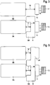
- the drive unit 5 for driving the milling drum 4 comprises a first and a second internal combustion engine 5A, 5B, in particular two diesel engines ( Fig. 3 . Fig. 4 ).
- both diesel engines are the same engines.
- the two diesel engines can also be motors of different design and / or performance.
- the first motor hereinafter referred to as the main motor 5A, is coupled via an articulated coupling device 7, for example a cardan shaft or elastomer coupling, to a pump distributor gearbox 8 (PVG) ( Fig. 3 ).
- a spur gear is arranged, which drives a plurality of hydraulic pumps 8A together, which are arranged distributed circumferentially ( Fig. 4 ).
- the arrangement of the hydraulic pumps 8A results in a central, free inner space 10 between the hydraulic pumps 8A, in which the coupling device 7 is located.
- a particularly space-saving arrangement of the components is achieved, so that in view of the predetermined transport width of the construction machine sufficient space for the transversely mounted engine is available.
- the pump distributor 8 is coupled via a device 11 for switching the torque, for example a clutch with a drive shaft 12, rotatably on a pulley 13 sits.
- the second motor hereinafter referred to as the auxiliary motor 5B, is arranged transversely to the direction of travel at a close distance from the main motor 5A (FIG. Fig. 3 ).
- the auxiliary motor 5B is coupled via a further articulated coupling device 14, for example a cardan shaft or elastomer coupling, to a second device 15 for switching the torque, for example a clutch, to which in turn a drive shaft 16 is coupled, on which a second belt pulley 17 is seated.
- the pump distributor 8 is not associated with the main motor 5A, but the sub motor 5B. It is also possible that not the pump distributor 8 directly to the main engine and the clutch 11 to the pump distributor gearbox, but the clutch 11 is coupled directly to the main engine and the pump distributor gearbox to the clutch. Then, the free space 10 of the pump distributor gear 8 instead of the coupling device 7, the clutch 11 record. In both cases results in a compact design.
- the hydraulic pumps 8A which are driven by the pump distributor 8, serve to drive additional units, but require a much lower power than the drive of the milling drum.
- the main and sub motors 5A, 5B are fixed to the machine frame 2 by means of elastic spring / damper means 21, which have a low spring rigidity, so that the vibrations occurring in particular in these motors are transmitted as little as possible to the machine frame.
- the remaining part of the drive train which includes the pump transfer case 8 of the main motor 5A, with spring / damping elements 23 attached to the machine frame 2, which have a high spring stiffness or rigid.
- an alternative embodiment with reference to the Fig. 2 . 5 and 6 described by the reference to the Fig. 2 . 3 and 4 described embodiment differs in that the addition of the benefits of the two motors 5A, 5B does not take place via a belt transmission, but a spur gear.
- the main motor 5A and the sub-motor 5B are connected to each other via a spur gear 21, which may be integrated into the pump transfer case 8 of the main motor 5A.
- spur gear 21 may be integrated into the pump transfer case 8 of the main motor 5A.
- the spur gear can have a clutch 15, which is integrated in the transmission unit.
- the coupling of the auxiliary motor 5A to the spur gear 21 is again via a coupling device 14 ', in particular propeller shaft or elastomer coupling.
- Fig. 6 shows that the drive belt 9 'on the main motor 5A associated pulley 13, the pulley 18 of the milling drum 4 and the tension roller 20' run, which is wrapped in this embodiment of the drive belt 9 'from the outside.
- a pulley may be provided on the output shaft of one motor and two pulleys on the output shaft of the other motor, with a first belt or belts running over the first pulley of the two pulleys of one engine and the pulley of the other engine.
- a second drive belt or belts may pass over the other of the two pulleys of the one motor and the pulley of the work roll. It is basically irrelevant whether one or the other engine is the main or auxiliary engine.
- This embodiment corresponds to the embodiment of Figures 5 and 6, wherein the two motors but not via the spur gear, but are coupled together via at least one other drive belt.
- the drive motors 5A, 5B of the drive unit of the construction machine according to the invention are preferably lightweight diesel engines in which, in principle, torsional vibrations can occur.
- crankshaft angle of the crankshaft of the first and second internal combustion engine 5A, 5B adjustable during operation of both internal combustion engines, so that the crankshaft of the first engine with respect to the crankshaft of the second motor by a selectable angle forward or can run after.
- the drive unit 4 has a control unit 19 for reducing the vibrations that occur in the FIGS. 4 and 5 is shown schematically.
- the control unit 19 is configured such that the crankshaft angle of the crankshaft, not shown, of the first internal combustion engine 5A with respect to the crankshaft angle of the crankshaft, not shown, of the second internal combustion engine 5B is set such that the torsional vibrations generated by both internal combustion engines in the common transmission of the drive power of First and second motor with the power transmission device 6 on the work unit 4 at least partially eliminate.
- the first motor 5A is operated so that its crankshaft protrudes by a certain angle
- the second motor 5B is operated so that its crankshaft lags by a certain angle.
- the attributable to the first and second motor torsional vibrations that are transmitted to the drive train are therefore shifted by a certain phase angle to each other.
- the control unit 19 adjusts the crankshaft angles such that the torsional vibrations superimposed in the drive train at least partially eliminate one another, ie vibrations with a specific amplitude in one direction compensate for vibrations of a similarly large amplitude in the opposite direction. The same applies to the other vibrations introduced in the machine frame.
Landscapes
- Engineering & Computer Science (AREA)
- Architecture (AREA)
- Civil Engineering (AREA)
- Structural Engineering (AREA)
- Mechanical Engineering (AREA)
- Mining & Mineral Resources (AREA)
- Road Paving Machines (AREA)
- Road Repair (AREA)
- Arrangement Of Transmissions (AREA)
- Operation Control Of Excavators (AREA)
Claims (16)
- Machine de fraisage avec
un bâti de machine (2) qui est porté par un mécanisme de roulement (1),
une unité de travail (4) pour la mise en oeuvre des travaux nécessaires au projet de construction qui présente un rouleau de fraisage (4) équipé de burins de fraisage,
une unité d'entraînement (5) portée par le bâti de machine (1) pour l'entraînement de l'unité de travail (4), et
un dispositif de transmission de forces (6) pour la transmission de la puissance d'entraînement de l'unité d'entraînement (5) à l'unité de travail (4),
caractérisée en ce que
le mécanisme de roulement (1) présente quatre organes de roulement sur chenille (1A, 1B) agencés sur le côté avant et arrière de la machine de fraisage sur les deux côtés du bâti de machine (1) qui sont fixés de manière réglable en hauteur sur des colonnes de levage (3) qui sont montées sur le bâti de machine (1),
l'unité de travail (4) est agencée sur le bâti de machine (1) dans le sens longitudinal de la machine de fraisage entre les organes de roulement sur chenille (1A,1B) avant et arrière, l'unité d'entraînement (5) présente un premier moteur d'entraînement (5A) et un second moteur d'entraînement (5B),
le dispositif de transmission de forces (6) est réalisé de telle manière que la puissance d'entraînement du premier et du second moteur d'entraînement (5A, 5B) puisse être transférée conjointement à l'unité de travail (4),
le premier et second moteur d'entraînement (5A, 5B) sont agencés sur le bâti de machine (1) dans le sens longitudinal de l'engin de chantier entre les colonnes de levage (3) des organes de roulement sur chenille (1A,1B) avant et arrière transversalement au sens de la marche de l'engin de chantier, et
le premier et second moteur d'entraînement (5A, 5B) sont agencés à distance l'un de l'autre dans un plan du bâti de machine (2) qui se trouve au-dessus du plan dans lequel l'unité de travail (4) est agencée sur le bâti de machine, dans laquelle le dispositif de transmission de forces (6) présente au moins une transmission à courroie (9, 13, 17, 18), permettant de transmettre simultanément la puissance d'entraînement du premier et second moteur d'entraînement (5A, 5B) à l'unité de travail (4) et
la transmission à courroie (9, 13, 17, 18) présente une première poulie à courroie (13) qui est reliée de manière solidaire en rotation à un premier arbre de sortie (12) pouvant être entraîné par le premier moteur d'entraînement (5A), et une deuxième poulie à courroie (17) qui est reliée de manière solidaire en rotation à un arbre de sortie (16) pouvant être entraîné par le second moteur d'entraînement (5B), et une troisième poulie à courroie (18) qui est reliée de manière solidaire en rotation à un arbre d'entraînement (4A) entraînant l'unité de travail (4), dans laquelle au moins une courroie d'entraînement (9) passe sur les poulies à courroie (13, 17, 18). - Machine de fraisage selon la revendication 1, caractérisée en ce que le dispositif de transmission de forces (6) présente un premier dispositif (11) pour la commutation du couple du premier moteur d'entraînement (5A) et/ou un second dispositif (15) pour la commutation du couple du second moteur d'entraînement (5B).
- Machine de fraisage selon la revendication 1 ou 2, caractérisée en ce que le premier et le second moteur d'entraînement (5A, 5B) sont des moteurs à combustion, notamment des moteurs diesel.
- Machine de fraisage selon l'une quelconque des revendications 1 à 3, caractérisée en ce que le premier moteur d'entraînement (5A) et le second moteur d'entraînement (5B) ont la même puissance.
- Machine de fraisage selon l'une quelconque des revendications 1 à 3, caractérisée en ce que le premier moteur d'entraînement (5A) présente une plus grande puissance que le second moteur d'entraînement (5B).
- Machine de fraisage selon l'une quelconque des revendications 1 à 3, caractérisée en ce que le premier et le second moteur d'entraînement (5A, 5B) sont des moteurs de même type.
- Machine de fraisage selon l'une quelconque des revendications 1 à 3, caractérisée en ce que le premier et le second moteur d'entraînement (5A, 5B) sont les mêmes moteurs d'entraînement.
- Machine de fraisage selon l'une quelconque des revendications 1 à 7, caractérisée en ce que le dispositif de transmission de forces (6) présente un dispositif (8) pour l'entraînement d'au moins une pompe hydraulique (8A).
- Machine de fraisage selon la revendication 8, caractérisée en ce que le dispositif (8) présente, pour l'entraînement d'au moins une pompe hydraulique, une boîte de distribution à pompe pour plusieurs pompes hydrauliques (8A).
- Machine de fraisage selon la revendication 8 ou 9, caractérisée en ce que le dispositif (8) est couplé au premier moteur d'entraînement (5A) pour l'entraînement d'au moins une pompe hydraulique.
- Machine de fraisage selon l'une quelconque des revendications 1 à 10, caractérisée en ce que le premier arbre de sortie (12) est couplé au premier moteur d'entraînement (5A) par le biais d'un premier dispositif de couplage articulé (7) et le second arbre de sortie (16) est couplé au second moteur d'entraînement (5A) par le biais d'un second dispositif de couplage articulé (14).
- Machine de fraisage selon la revendication 2, ou selon la revendication 2 et en outre l'une quelconque des revendications 3 à 11, caractérisée en ce que le premier dispositif (11) est disposé pour la commutation du couple du premier moteur d'entraînement (5A) entre le moteur d'entraînement (5A) et le premier arbre de sortie (12).
- Machine de fraisage selon la revendication 2, ou selon la revendication 2 et en outre l'une quelconque des revendications 3 à 12, caractérisée en ce que le second dispositif (15) est disposé pour la commutation du couple du second moteur d'entraînement (5B) entre le moteur d'entraînement (5B) et le second arbre de sortie (16).
- Machine de fraisage selon la revendication 8, ou selon la revendication 8 et en outre l'une quelconque des revendications 9 à 13, caractérisée en ce que le dispositif (8) est disposé pour l'entraînement d'au moins une pompe hydraulique entre le premier moteur d'entraînement (5A) et le premier arbre de sortie (12).
- Machine de fraisage selon l'une quelconque des revendications 1 à 14, caractérisée en ce que le premier moteur d'entraînement (5A) et le second moteur d'entraînement (5B) sont des moteurs à combustion avec des vilebrequins, dans laquelle l'angle de vilebrequin du vilebrequin du premier moteur peut être réglé par rapport à l'angle de vilebrequin du vilebrequin du second moteur.
- Machine de fraisage selon la revendication 15, caractérisée en ce que l'angle de vilebrequin du vilebrequin du premier moteur d'entraînement (5A) peut être réglé par rapport à l'angle de vilebrequin du vilebrequin du second moteur d'entraînement (5B) de telle manière que les vibrations torsionnelles générées par les deux moteurs s'éliminent au moins en partie lors de la transmission commune de la puissance d'entraînement du premier et du second moteur d'entraînement (5A, 5B) à l'unité de travail (4).
Applications Claiming Priority (2)
| Application Number | Priority Date | Filing Date | Title |
|---|---|---|---|
| DE102007019202.0A DE102007019202B4 (de) | 2007-04-20 | 2007-04-20 | Selbstfahrende Baumaschine, inbesondere Straßenfräsmaschine, Recycler oder Stabilisierer |
| EP08005940.5A EP1983105B1 (fr) | 2007-04-20 | 2008-03-28 | Engin de travaux publics automoteur, en particulier machine de fraisage, recycleur ou stabilisateur |
Related Parent Applications (2)
| Application Number | Title | Priority Date | Filing Date |
|---|---|---|---|
| EP08005940.5A Division EP1983105B1 (fr) | 2007-04-20 | 2008-03-28 | Engin de travaux publics automoteur, en particulier machine de fraisage, recycleur ou stabilisateur |
| EP08005940.5 Division | 2008-03-28 |
Publications (3)
| Publication Number | Publication Date |
|---|---|
| EP2672009A2 EP2672009A2 (fr) | 2013-12-11 |
| EP2672009A3 EP2672009A3 (fr) | 2014-08-13 |
| EP2672009B1 true EP2672009B1 (fr) | 2019-05-08 |
Family
ID=39590541
Family Applications (2)
| Application Number | Title | Priority Date | Filing Date |
|---|---|---|---|
| EP08005940.5A Active EP1983105B1 (fr) | 2007-04-20 | 2008-03-28 | Engin de travaux publics automoteur, en particulier machine de fraisage, recycleur ou stabilisateur |
| EP13183034.1A Active EP2672009B1 (fr) | 2007-04-20 | 2008-03-28 | Machine de construction automotrice, notamment machine à fraiser la chaussée, recycleur ou stabilisateur |
Family Applications Before (1)
| Application Number | Title | Priority Date | Filing Date |
|---|---|---|---|
| EP08005940.5A Active EP1983105B1 (fr) | 2007-04-20 | 2008-03-28 | Engin de travaux publics automoteur, en particulier machine de fraisage, recycleur ou stabilisateur |
Country Status (8)
| Country | Link |
|---|---|
| US (2) | US7976106B2 (fr) |
| EP (2) | EP1983105B1 (fr) |
| JP (1) | JP5336755B2 (fr) |
| CN (3) | CN104404859B (fr) |
| AU (1) | AU2008201543B2 (fr) |
| BR (1) | BRPI0801164B1 (fr) |
| DE (1) | DE102007019202B4 (fr) |
| RU (1) | RU2467117C2 (fr) |
Families Citing this family (28)
| Publication number | Priority date | Publication date | Assignee | Title |
|---|---|---|---|---|
| DE102007019202B4 (de) * | 2007-04-20 | 2015-05-21 | Wirtgen Gmbh | Selbstfahrende Baumaschine, inbesondere Straßenfräsmaschine, Recycler oder Stabilisierer |
| BRPI0805496B1 (pt) | 2008-12-19 | 2012-07-10 | usina e método para produzir mistura asfáltica quente utilizando percentagem total de produto asfáltico fresado e para aquecer, secar e misturar o mesmo utilizando energia solar térmica combinada (estc). | |
| DE102009059106A1 (de) * | 2009-12-18 | 2011-06-22 | Wirtgen GmbH, 53578 | Selbstfahrende Baumaschine und Verfahren zur Steuerung einer selbstfahrenden Baumaschine |
| EP2372022B1 (fr) * | 2010-03-23 | 2014-12-31 | Joseph Vögele AG | Engin de construction routière |
| US20120068525A1 (en) * | 2010-09-17 | 2012-03-22 | Diamond Products, Limited | Concrete saw having multiple motors |
| DE102011116268A1 (de) * | 2011-10-19 | 2013-04-25 | Wirtgen Gmbh | Selbstfahrende Baumaschine |
| CN102431446A (zh) * | 2011-11-28 | 2012-05-02 | 三一汽车起重机械有限公司 | 一种工程车及其驱动系统 |
| DE102012024452A1 (de) | 2011-12-15 | 2013-06-20 | Bomag Gmbh | Baumaschine oder Landmaschine mit einer rotierenden Arbeitseinrichtung und Verfahren zum Antreiben der rotierenden Arbeitseinrchtung |
| DE102012001289A1 (de) * | 2012-01-25 | 2013-07-25 | Wirtgen Gmbh | Selbstfahrende Baumaschine und Verfahren zum Steuern einer selbstfahrenden Baumaschine |
| DE102012006189A1 (de) * | 2012-03-27 | 2013-10-02 | Bomag Gmbh | Antriebsvorrichtung in einer selbstfahrenden Baumaschine sowie Verfahren zum Einstellen eines Drehzahlverhältnisses bei einer derartigen Antriebsvorrichtung |
| CN103374873B (zh) * | 2012-04-27 | 2016-01-20 | 常州杰和机械有限公司 | 小型驾驶的路面铣刨机 |
| CN102828462B (zh) * | 2012-09-20 | 2015-07-29 | 中联重科股份有限公司 | 铣刨机的机械传动系统和控制方法及铣刨机 |
| JP6076013B2 (ja) * | 2012-09-26 | 2017-02-08 | 株式会社神戸製鋼所 | 建設機械 |
| DE102012024770B4 (de) * | 2012-12-18 | 2024-03-14 | Bomag Gmbh | Selbstfahrende Baumaschine |
| US8905488B2 (en) | 2013-02-19 | 2014-12-09 | Caterpillar Paving Products Inc. | Auxiliary drivetrain for a cold planer |
| US9175449B2 (en) * | 2013-03-13 | 2015-11-03 | Caterpillar Paving Products Inc. | Transmission system for transmitting power from engine to milling rotor in cold planer |
| DE102013019448A1 (de) | 2013-11-21 | 2015-06-03 | Wirtgen Gmbh | Selbstfahrende Baumaschine |
| AU2015206254B2 (en) | 2014-01-18 | 2019-02-21 | Diamond Products, Limited | Electric concrete saw |
| JP5639291B1 (ja) * | 2014-01-24 | 2014-12-10 | 仲山鉄工株式会社 | 舗装材切断装置の駆動機構 |
| DE102014011195C5 (de) | 2014-07-28 | 2025-10-16 | Bomag Gmbh | Bodenfräsmaschine mit von einem Wartungsmotor betriebenem Kompressor und Verfahren zum Betrieb einer solchen Bodenfräsmaschine |
| US10676881B2 (en) | 2015-10-22 | 2020-06-09 | Desch Antriebstechnik Gmbh & Co. Kg | Drive device for a construction machine |
| DE102016121672A1 (de) * | 2016-11-11 | 2018-05-17 | Rheinmetall Landsysteme Gmbh | Antrieb für Fahrzeuge insbesondere Gefechtsfahrzeuge |
| US10480135B2 (en) * | 2017-01-03 | 2019-11-19 | Roadtec, Inc. | Cold in-place recycling with heating assembly including a heater for asphalt cement and a heat-modifying component |
| DE102017204336A1 (de) | 2017-03-15 | 2018-09-20 | Wirtgen Gmbh | Bodenbearbeitungsmaschine mit Schaltgetriebe zwischen Antriebsmotor und rotierbarer Arbeitsvorrichtung |
| CN111005281B (zh) * | 2019-11-25 | 2022-05-17 | 济宁市公路工程总公司 | 公路路面施工设备及利用其实现的公路路面施工方法 |
| CN111336007B (zh) * | 2020-03-07 | 2021-08-06 | 罗仙花 | 一种带断带保护功能的风冷发动机组 |
| CN114908643B (zh) * | 2022-05-24 | 2025-01-28 | 高少磊 | 一种全覆盖式作业的自动刻纹机及其工作方法 |
| DE102022122472B4 (de) | 2022-09-05 | 2024-03-28 | Wirtgen Gmbh | Selbstfahrende Bodenbearbeitungsmaschine mit Zwillingsmotoren und einem deren Leistung unterschiedlich übertragenden Arbeitsgetriebe |
Citations (3)
| Publication number | Priority date | Publication date | Assignee | Title |
|---|---|---|---|---|
| EP1167626A1 (fr) * | 2000-06-27 | 2002-01-02 | WIRTGEN GmbH | Machine de construction pour traiter des surfaces |
| WO2004005623A1 (fr) * | 2002-07-09 | 2004-01-15 | Wirtgen Gmbh | Fraiseuse de route automotrice |
| EP1640201A1 (fr) * | 2004-09-24 | 2006-03-29 | Maschinenfabrik Bernard Krone GmbH | Moissonneuse automotrice |
Family Cites Families (20)
| Publication number | Priority date | Publication date | Assignee | Title |
|---|---|---|---|---|
| US2173541A (en) * | 1936-05-29 | 1939-09-19 | Rieger Willy | Compound engine |
| FR1474154A (fr) | 1966-02-09 | 1967-03-24 | Renault | Perfectionnements aux groupes moteur-transmission pour véhicules automobiles ou analogues |
| JPS5172808A (ja) * | 1974-12-19 | 1976-06-24 | Mitsubishi Motors Corp | Nenpikeigengatajidoshayokudosochi |
| US3948049A (en) * | 1975-05-01 | 1976-04-06 | Caterpillar Tractor Co. | Dual motor hydrostatic drive system |
| US4193636A (en) * | 1978-07-10 | 1980-03-18 | Jakob Herbert E | Asphalt paving planer with conveyor forwardly of cutting drum |
| JPS5793652A (en) * | 1980-11-29 | 1982-06-10 | Fuji Heavy Ind Ltd | Internal combustion engine with plural power sources |
| JPH0315611Y2 (fr) * | 1986-04-16 | 1991-04-04 | ||
| AU5554290A (en) * | 1989-05-01 | 1990-11-29 | Louris Bood | Electric machine |
| CN2082730U (zh) * | 1990-05-24 | 1991-08-14 | 吉林省公路机械厂 | 稀浆封层机 |
| US5063713A (en) * | 1990-12-20 | 1991-11-12 | Accent Stripe Inc. | Surface abrading and particle collection device |
| US5382084A (en) * | 1993-07-28 | 1995-01-17 | Alitec Corporation | Milling drum with internal drive motor |
| US5676490A (en) * | 1996-04-08 | 1997-10-14 | Nelson; Dale J. | Machine for cutting highway rumble strips |
| US20020084120A1 (en) * | 2001-01-02 | 2002-07-04 | Beasley Leslie R. | Motor assembly with independent motor units |
| US20040005190A1 (en) * | 2002-07-08 | 2004-01-08 | Gerhard Jakits | Device and method for selectively milling the surface of a roadway |
| RU2229565C1 (ru) * | 2002-12-04 | 2004-05-27 | Военный инженерно-технический университет | Способ автономного энергообеспечения приводных устройств строительных и подобных им машин |
| JP2005171559A (ja) * | 2003-12-09 | 2005-06-30 | Komatsu Ltd | 散布装置 |
| DE102005017754A1 (de) * | 2005-04-15 | 2006-10-19 | Wirtgen Gmbh | Baumaschine insbesondere Strassenfräsmaschine, Recycler oder Stabilisierer, sowie Antriebsstrang für derartige Baumaschinen |
| DE102006006766A1 (de) * | 2006-02-13 | 2007-08-23 | Claas Selbstfahrende Erntemaschinen Gmbh | Motorfahrzeug |
| DE102007019202B4 (de) * | 2007-04-20 | 2015-05-21 | Wirtgen Gmbh | Selbstfahrende Baumaschine, inbesondere Straßenfräsmaschine, Recycler oder Stabilisierer |
| EP2346159A1 (fr) * | 2007-10-19 | 2011-07-20 | Caterpillar Motoren GmbH & Co. KG | Système d'alimentation doté d'une double synchronisation |
-
2007
- 2007-04-20 DE DE102007019202.0A patent/DE102007019202B4/de active Active
-
2008
- 2008-03-28 EP EP08005940.5A patent/EP1983105B1/fr active Active
- 2008-03-28 EP EP13183034.1A patent/EP2672009B1/fr active Active
- 2008-04-04 AU AU2008201543A patent/AU2008201543B2/en active Active
- 2008-04-16 US US12/104,293 patent/US7976106B2/en active Active
- 2008-04-17 JP JP2008107609A patent/JP5336755B2/ja active Active
- 2008-04-18 BR BRPI0801164-8A patent/BRPI0801164B1/pt active IP Right Grant
- 2008-04-18 RU RU2008115345/03A patent/RU2467117C2/ru active
- 2008-04-21 CN CN201410513495.8A patent/CN104404859B/zh active Active
- 2008-04-21 CN CN200810095014.0A patent/CN101319486A/zh active Pending
- 2008-04-21 CN CN200820105127.XU patent/CN201367550Y/zh not_active Expired - Lifetime
-
2011
- 2011-05-31 US US13/118,742 patent/US8974006B2/en active Active
Patent Citations (3)
| Publication number | Priority date | Publication date | Assignee | Title |
|---|---|---|---|---|
| EP1167626A1 (fr) * | 2000-06-27 | 2002-01-02 | WIRTGEN GmbH | Machine de construction pour traiter des surfaces |
| WO2004005623A1 (fr) * | 2002-07-09 | 2004-01-15 | Wirtgen Gmbh | Fraiseuse de route automotrice |
| EP1640201A1 (fr) * | 2004-09-24 | 2006-03-29 | Maschinenfabrik Bernard Krone GmbH | Moissonneuse automotrice |
Also Published As
| Publication number | Publication date |
|---|---|
| EP1983105B1 (fr) | 2013-10-09 |
| JP5336755B2 (ja) | 2013-11-06 |
| BRPI0801164A2 (pt) | 2008-12-02 |
| US7976106B2 (en) | 2011-07-12 |
| RU2008115345A (ru) | 2009-10-27 |
| EP2672009A2 (fr) | 2013-12-11 |
| US20110227393A1 (en) | 2011-09-22 |
| EP2672009A3 (fr) | 2014-08-13 |
| BRPI0801164B1 (pt) | 2018-06-12 |
| CN104404859A (zh) | 2015-03-11 |
| JP2008274748A (ja) | 2008-11-13 |
| RU2467117C2 (ru) | 2012-11-20 |
| EP1983105A3 (fr) | 2011-12-14 |
| AU2008201543B2 (en) | 2014-05-01 |
| AU2008201543A1 (en) | 2008-11-06 |
| US8974006B2 (en) | 2015-03-10 |
| US20080260461A1 (en) | 2008-10-23 |
| CN201367550Y (zh) | 2009-12-23 |
| CN104404859B (zh) | 2019-06-21 |
| DE102007019202B4 (de) | 2015-05-21 |
| EP1983105A2 (fr) | 2008-10-22 |
| DE102007019202A1 (de) | 2008-10-30 |
| CN101319486A (zh) | 2008-12-10 |
Similar Documents
| Publication | Publication Date | Title |
|---|---|---|
| EP2672009B1 (fr) | Machine de construction automotrice, notamment machine à fraiser la chaussée, recycleur ou stabilisateur | |
| EP1704283B1 (fr) | Machine automotrice servant a realiser des voies de circulation | |
| EP2584095B1 (fr) | Engin automobile et procédé de contrôle d'un tel engin | |
| WO1996024725A1 (fr) | Engin pour travaux routiers | |
| DE102004046467B4 (de) | Selbstfahrende Erntemaschine | |
| EP3719202B1 (fr) | Machine de traitement du sol | |
| DE112005003288B4 (de) | Tragstruktur für eine Fahrzeugantriebseinheit | |
| EP1875004B1 (fr) | Engin de chantier, notamment machine a fraiser la chaussee, recycleur ou stabilisateur et chaine cinematique pour ce type d'engins de chantier | |
| EP2712837B1 (fr) | Machine de travail automobile | |
| EP3569478A1 (fr) | Véhicule à chenilles agricole | |
| DE60017036T2 (de) | Handhabungsfahrzeug für Material | |
| DE60317975T2 (de) | Stufenloses Getriebe für Kraftfahrzeuge, insbesondere für landwirtschaftliche Traktoren | |
| DE102009028094B4 (de) | Selbstfahrende Erntemaschine | |
| EP2269439B1 (fr) | Moissonneuse agricole automobile dotée de deux moteurs à combustion | |
| DE102006020663A1 (de) | Anbaugerät für Arbeitsmaschinen | |
| DE202017107240U1 (de) | Arbeitsgerät, Arbeitsfahrzeug mit einem solchen Arbeitsgerät sowie Baukasten zum Herstellen des Arbeitsgerätes | |
| EP1749938B1 (fr) | Dispositif de coupe mobile avec unité d'entraînement isolée vibratoirement | |
| EP2789825B1 (fr) | Moissonneuse | |
| DE102006041784A1 (de) | Schwingungserreger | |
| WO2010023180A1 (fr) | Broyeur à cylindre | |
| AT397826B (de) | Anbauvorrichtung für eine an ein handelsübliches motorfahrzeug mit einem stirnseitig vorgesehenen führerhaus ankuppelbare schneeräumeinrichtung | |
| DE1010011B (de) | Maschine zum Rueckfuehren oder Abtragen von Erz und aehnlichem Schuettgut | |
| DE102022108579A1 (de) | Fahrzeuganordnung mit einer Hubeinrichtung sowie ein Verfahren zum Betrieb einer Fahrzeuganordnung | |
| DE102022109145A1 (de) | Tandemwalze | |
| DE102007020349A1 (de) | Antriebssystem für ein Fahrzeug |
Legal Events
| Date | Code | Title | Description |
|---|---|---|---|
| PUAI | Public reference made under article 153(3) epc to a published international application that has entered the european phase |
Free format text: ORIGINAL CODE: 0009012 |
|
| 17P | Request for examination filed |
Effective date: 20130904 |
|
| AC | Divisional application: reference to earlier application |
Ref document number: 1983105 Country of ref document: EP Kind code of ref document: P |
|
| AK | Designated contracting states |
Kind code of ref document: A2 Designated state(s): AT BE BG CH CY CZ DE DK EE ES FI FR GB GR HR HU IE IS IT LI LT LU LV MC MT NL NO PL PT RO SE SI SK TR |
|
| RIN1 | Information on inventor provided before grant (corrected) |
Inventor name: BERNING, CHRISTIAN Inventor name: BUSLEY, PETER Inventor name: SIMONS, DIETER |
|
| PUAL | Search report despatched |
Free format text: ORIGINAL CODE: 0009013 |
|
| AK | Designated contracting states |
Kind code of ref document: A3 Designated state(s): AT BE BG CH CY CZ DE DK EE ES FI FR GB GR HR HU IE IS IT LI LT LU LV MC MT NL NO PL PT RO SE SI SK TR |
|
| RIC1 | Information provided on ipc code assigned before grant |
Ipc: E01C 21/00 20060101ALI20140704BHEP Ipc: B60K 25/02 20060101ALI20140704BHEP Ipc: E01C 23/088 20060101AFI20140704BHEP |
|
| 17Q | First examination report despatched |
Effective date: 20160913 |
|
| STAA | Information on the status of an ep patent application or granted ep patent |
Free format text: STATUS: EXAMINATION IS IN PROGRESS |
|
| GRAP | Despatch of communication of intention to grant a patent |
Free format text: ORIGINAL CODE: EPIDOSNIGR1 |
|
| STAA | Information on the status of an ep patent application or granted ep patent |
Free format text: STATUS: GRANT OF PATENT IS INTENDED |
|
| INTG | Intention to grant announced |
Effective date: 20181018 |
|
| GRAS | Grant fee paid |
Free format text: ORIGINAL CODE: EPIDOSNIGR3 |
|
| GRAA | (expected) grant |
Free format text: ORIGINAL CODE: 0009210 |
|
| STAA | Information on the status of an ep patent application or granted ep patent |
Free format text: STATUS: THE PATENT HAS BEEN GRANTED |
|
| AC | Divisional application: reference to earlier application |
Ref document number: 1983105 Country of ref document: EP Kind code of ref document: P |
|
| AK | Designated contracting states |
Kind code of ref document: B1 Designated state(s): AT BE BG CH CY CZ DE DK EE ES FI FR GB GR HR HU IE IS IT LI LT LU LV MC MT NL NO PL PT RO SE SI SK TR |
|
| REG | Reference to a national code |
Ref country code: GB Ref legal event code: FG4D Free format text: NOT ENGLISH |
|
| REG | Reference to a national code |
Ref country code: CH Ref legal event code: EP Ref country code: AT Ref legal event code: REF Ref document number: 1130314 Country of ref document: AT Kind code of ref document: T Effective date: 20190515 |
|
| REG | Reference to a national code |
Ref country code: DE Ref legal event code: R096 Ref document number: 502008016749 Country of ref document: DE |
|
| REG | Reference to a national code |
Ref country code: IE Ref legal event code: FG4D Free format text: LANGUAGE OF EP DOCUMENT: GERMAN |
|
| REG | Reference to a national code |
Ref country code: SE Ref legal event code: TRGR |
|
| REG | Reference to a national code |
Ref country code: NL Ref legal event code: MP Effective date: 20190508 |
|
| REG | Reference to a national code |
Ref country code: LT Ref legal event code: MG4D |
|
| PG25 | Lapsed in a contracting state [announced via postgrant information from national office to epo] |
Ref country code: HR Free format text: LAPSE BECAUSE OF FAILURE TO SUBMIT A TRANSLATION OF THE DESCRIPTION OR TO PAY THE FEE WITHIN THE PRESCRIBED TIME-LIMIT Effective date: 20190508 Ref country code: NL Free format text: LAPSE BECAUSE OF FAILURE TO SUBMIT A TRANSLATION OF THE DESCRIPTION OR TO PAY THE FEE WITHIN THE PRESCRIBED TIME-LIMIT Effective date: 20190508 Ref country code: LT Free format text: LAPSE BECAUSE OF FAILURE TO SUBMIT A TRANSLATION OF THE DESCRIPTION OR TO PAY THE FEE WITHIN THE PRESCRIBED TIME-LIMIT Effective date: 20190508 Ref country code: ES Free format text: LAPSE BECAUSE OF FAILURE TO SUBMIT A TRANSLATION OF THE DESCRIPTION OR TO PAY THE FEE WITHIN THE PRESCRIBED TIME-LIMIT Effective date: 20190508 Ref country code: NO Free format text: LAPSE BECAUSE OF FAILURE TO SUBMIT A TRANSLATION OF THE DESCRIPTION OR TO PAY THE FEE WITHIN THE PRESCRIBED TIME-LIMIT Effective date: 20190808 Ref country code: FI Free format text: LAPSE BECAUSE OF FAILURE TO SUBMIT A TRANSLATION OF THE DESCRIPTION OR TO PAY THE FEE WITHIN THE PRESCRIBED TIME-LIMIT Effective date: 20190508 Ref country code: PT Free format text: LAPSE BECAUSE OF FAILURE TO SUBMIT A TRANSLATION OF THE DESCRIPTION OR TO PAY THE FEE WITHIN THE PRESCRIBED TIME-LIMIT Effective date: 20190908 |
|
| PG25 | Lapsed in a contracting state [announced via postgrant information from national office to epo] |
Ref country code: LV Free format text: LAPSE BECAUSE OF FAILURE TO SUBMIT A TRANSLATION OF THE DESCRIPTION OR TO PAY THE FEE WITHIN THE PRESCRIBED TIME-LIMIT Effective date: 20190508 Ref country code: GR Free format text: LAPSE BECAUSE OF FAILURE TO SUBMIT A TRANSLATION OF THE DESCRIPTION OR TO PAY THE FEE WITHIN THE PRESCRIBED TIME-LIMIT Effective date: 20190809 Ref country code: BG Free format text: LAPSE BECAUSE OF FAILURE TO SUBMIT A TRANSLATION OF THE DESCRIPTION OR TO PAY THE FEE WITHIN THE PRESCRIBED TIME-LIMIT Effective date: 20190808 |
|
| PG25 | Lapsed in a contracting state [announced via postgrant information from national office to epo] |
Ref country code: RO Free format text: LAPSE BECAUSE OF FAILURE TO SUBMIT A TRANSLATION OF THE DESCRIPTION OR TO PAY THE FEE WITHIN THE PRESCRIBED TIME-LIMIT Effective date: 20190508 Ref country code: CZ Free format text: LAPSE BECAUSE OF FAILURE TO SUBMIT A TRANSLATION OF THE DESCRIPTION OR TO PAY THE FEE WITHIN THE PRESCRIBED TIME-LIMIT Effective date: 20190508 Ref country code: DK Free format text: LAPSE BECAUSE OF FAILURE TO SUBMIT A TRANSLATION OF THE DESCRIPTION OR TO PAY THE FEE WITHIN THE PRESCRIBED TIME-LIMIT Effective date: 20190508 Ref country code: EE Free format text: LAPSE BECAUSE OF FAILURE TO SUBMIT A TRANSLATION OF THE DESCRIPTION OR TO PAY THE FEE WITHIN THE PRESCRIBED TIME-LIMIT Effective date: 20190508 Ref country code: SK Free format text: LAPSE BECAUSE OF FAILURE TO SUBMIT A TRANSLATION OF THE DESCRIPTION OR TO PAY THE FEE WITHIN THE PRESCRIBED TIME-LIMIT Effective date: 20190508 |
|
| REG | Reference to a national code |
Ref country code: DE Ref legal event code: R097 Ref document number: 502008016749 Country of ref document: DE |
|
| PLBE | No opposition filed within time limit |
Free format text: ORIGINAL CODE: 0009261 |
|
| STAA | Information on the status of an ep patent application or granted ep patent |
Free format text: STATUS: NO OPPOSITION FILED WITHIN TIME LIMIT |
|
| PG25 | Lapsed in a contracting state [announced via postgrant information from national office to epo] |
Ref country code: TR Free format text: LAPSE BECAUSE OF FAILURE TO SUBMIT A TRANSLATION OF THE DESCRIPTION OR TO PAY THE FEE WITHIN THE PRESCRIBED TIME-LIMIT Effective date: 20190508 |
|
| 26N | No opposition filed |
Effective date: 20200211 |
|
| PG25 | Lapsed in a contracting state [announced via postgrant information from national office to epo] |
Ref country code: PL Free format text: LAPSE BECAUSE OF FAILURE TO SUBMIT A TRANSLATION OF THE DESCRIPTION OR TO PAY THE FEE WITHIN THE PRESCRIBED TIME-LIMIT Effective date: 20190508 |
|
| PG25 | Lapsed in a contracting state [announced via postgrant information from national office to epo] |
Ref country code: SI Free format text: LAPSE BECAUSE OF FAILURE TO SUBMIT A TRANSLATION OF THE DESCRIPTION OR TO PAY THE FEE WITHIN THE PRESCRIBED TIME-LIMIT Effective date: 20190508 |
|
| PG25 | Lapsed in a contracting state [announced via postgrant information from national office to epo] |
Ref country code: MC Free format text: LAPSE BECAUSE OF FAILURE TO SUBMIT A TRANSLATION OF THE DESCRIPTION OR TO PAY THE FEE WITHIN THE PRESCRIBED TIME-LIMIT Effective date: 20190508 |
|
| REG | Reference to a national code |
Ref country code: CH Ref legal event code: PL |
|
| REG | Reference to a national code |
Ref country code: BE Ref legal event code: MM Effective date: 20200331 |
|
| PG25 | Lapsed in a contracting state [announced via postgrant information from national office to epo] |
Ref country code: LU Free format text: LAPSE BECAUSE OF NON-PAYMENT OF DUE FEES Effective date: 20200328 |
|
| PG25 | Lapsed in a contracting state [announced via postgrant information from national office to epo] |
Ref country code: CH Free format text: LAPSE BECAUSE OF NON-PAYMENT OF DUE FEES Effective date: 20200331 Ref country code: LI Free format text: LAPSE BECAUSE OF NON-PAYMENT OF DUE FEES Effective date: 20200331 Ref country code: IE Free format text: LAPSE BECAUSE OF NON-PAYMENT OF DUE FEES Effective date: 20200328 |
|
| PG25 | Lapsed in a contracting state [announced via postgrant information from national office to epo] |
Ref country code: BE Free format text: LAPSE BECAUSE OF NON-PAYMENT OF DUE FEES Effective date: 20200331 |
|
| REG | Reference to a national code |
Ref country code: AT Ref legal event code: MM01 Ref document number: 1130314 Country of ref document: AT Kind code of ref document: T Effective date: 20200328 |
|
| PG25 | Lapsed in a contracting state [announced via postgrant information from national office to epo] |
Ref country code: AT Free format text: LAPSE BECAUSE OF NON-PAYMENT OF DUE FEES Effective date: 20200328 |
|
| PG25 | Lapsed in a contracting state [announced via postgrant information from national office to epo] |
Ref country code: MT Free format text: LAPSE BECAUSE OF FAILURE TO SUBMIT A TRANSLATION OF THE DESCRIPTION OR TO PAY THE FEE WITHIN THE PRESCRIBED TIME-LIMIT Effective date: 20190508 Ref country code: CY Free format text: LAPSE BECAUSE OF FAILURE TO SUBMIT A TRANSLATION OF THE DESCRIPTION OR TO PAY THE FEE WITHIN THE PRESCRIBED TIME-LIMIT Effective date: 20190508 |
|
| PG25 | Lapsed in a contracting state [announced via postgrant information from national office to epo] |
Ref country code: IS Free format text: LAPSE BECAUSE OF FAILURE TO SUBMIT A TRANSLATION OF THE DESCRIPTION OR TO PAY THE FEE WITHIN THE PRESCRIBED TIME-LIMIT Effective date: 20190908 |
|
| P01 | Opt-out of the competence of the unified patent court (upc) registered |
Effective date: 20230525 |
|
| PGFP | Annual fee paid to national office [announced via postgrant information from national office to epo] |
Ref country code: IT Payment date: 20250331 Year of fee payment: 18 |
|
| PGFP | Annual fee paid to national office [announced via postgrant information from national office to epo] |
Ref country code: SE Payment date: 20260323 Year of fee payment: 19 |
|
| PGFP | Annual fee paid to national office [announced via postgrant information from national office to epo] |
Ref country code: GB Payment date: 20260324 Year of fee payment: 19 |
|
| PGFP | Annual fee paid to national office [announced via postgrant information from national office to epo] |
Ref country code: DE Payment date: 20260320 Year of fee payment: 19 |
|
| PGFP | Annual fee paid to national office [announced via postgrant information from national office to epo] |
Ref country code: FR Payment date: 20260325 Year of fee payment: 19 |