EP2672087A2 - Kondensationswasserablass-Steuermechanismus - Google Patents
Kondensationswasserablass-Steuermechanismus Download PDFInfo
- Publication number
- EP2672087A2 EP2672087A2 EP13170680.6A EP13170680A EP2672087A2 EP 2672087 A2 EP2672087 A2 EP 2672087A2 EP 13170680 A EP13170680 A EP 13170680A EP 2672087 A2 EP2672087 A2 EP 2672087A2
- Authority
- EP
- European Patent Office
- Prior art keywords
- pressure
- condensation water
- control section
- bypass valve
- pipe passage
- Prior art date
- Legal status (The legal status is an assumption and is not a legal conclusion. Google has not performed a legal analysis and makes no representation as to the accuracy of the status listed.)
- Granted
Links
Images



Classifications
-
- F—MECHANICAL ENGINEERING; LIGHTING; HEATING; WEAPONS; BLASTING
- F02—COMBUSTION ENGINES; HOT-GAS OR COMBUSTION-PRODUCT ENGINE PLANTS
- F02B—INTERNAL-COMBUSTION PISTON ENGINES; COMBUSTION ENGINES IN GENERAL
- F02B29/00—Engines characterised by provision for charging or scavenging not provided for in groups F02B25/00, F02B27/00 or F02B33/00 - F02B39/00; Details thereof
- F02B29/04—Cooling of air intake supply
- F02B29/0406—Layout of the intake air cooling or coolant circuit
- F02B29/0437—Liquid cooled heat exchangers
-
- F—MECHANICAL ENGINEERING; LIGHTING; HEATING; WEAPONS; BLASTING
- F02—COMBUSTION ENGINES; HOT-GAS OR COMBUSTION-PRODUCT ENGINE PLANTS
- F02B—INTERNAL-COMBUSTION PISTON ENGINES; COMBUSTION ENGINES IN GENERAL
- F02B29/00—Engines characterised by provision for charging or scavenging not provided for in groups F02B25/00, F02B27/00 or F02B33/00 - F02B39/00; Details thereof
- F02B29/04—Cooling of air intake supply
- F02B29/045—Constructional details of the heat exchangers, e.g. pipes, plates, ribs, insulation, materials, or manufacturing and assembly
- F02B29/0468—Water separation or drainage means
-
- F—MECHANICAL ENGINEERING; LIGHTING; HEATING; WEAPONS; BLASTING
- F02—COMBUSTION ENGINES; HOT-GAS OR COMBUSTION-PRODUCT ENGINE PLANTS
- F02M—SUPPLYING COMBUSTION ENGINES IN GENERAL WITH COMBUSTIBLE MIXTURES OR CONSTITUENTS THEREOF
- F02M26/00—Engine-pertinent apparatus for adding exhaust gases to combustion-air, main fuel or fuel-air mixture, e.g. by exhaust gas recirculation [EGR] systems
- F02M26/02—EGR systems specially adapted for supercharged engines
- F02M26/04—EGR systems specially adapted for supercharged engines with a single turbocharger
- F02M26/05—High pressure loops, i.e. wherein recirculated exhaust gas is taken out from the exhaust system upstream of the turbine and reintroduced into the intake system downstream of the compressor
-
- F—MECHANICAL ENGINEERING; LIGHTING; HEATING; WEAPONS; BLASTING
- F02—COMBUSTION ENGINES; HOT-GAS OR COMBUSTION-PRODUCT ENGINE PLANTS
- F02M—SUPPLYING COMBUSTION ENGINES IN GENERAL WITH COMBUSTIBLE MIXTURES OR CONSTITUENTS THEREOF
- F02M26/00—Engine-pertinent apparatus for adding exhaust gases to combustion-air, main fuel or fuel-air mixture, e.g. by exhaust gas recirculation [EGR] systems
- F02M26/02—EGR systems specially adapted for supercharged engines
- F02M26/04—EGR systems specially adapted for supercharged engines with a single turbocharger
- F02M26/06—Low pressure loops, i.e. wherein recirculated exhaust gas is taken out from the exhaust downstream of the turbocharger turbine and reintroduced into the intake system upstream of the compressor
-
- Y—GENERAL TAGGING OF NEW TECHNOLOGICAL DEVELOPMENTS; GENERAL TAGGING OF CROSS-SECTIONAL TECHNOLOGIES SPANNING OVER SEVERAL SECTIONS OF THE IPC; TECHNICAL SUBJECTS COVERED BY FORMER USPC CROSS-REFERENCE ART COLLECTIONS [XRACs] AND DIGESTS
- Y02—TECHNOLOGIES OR APPLICATIONS FOR MITIGATION OR ADAPTATION AGAINST CLIMATE CHANGE
- Y02T—CLIMATE CHANGE MITIGATION TECHNOLOGIES RELATED TO TRANSPORTATION
- Y02T10/00—Road transport of goods or passengers
- Y02T10/10—Internal combustion engine [ICE] based vehicles
- Y02T10/12—Improving ICE efficiencies
Definitions
- the present invention relates to a condensation water drain control mechanism which drains water which is condensed in an intake pipe passage of an internal combustion engine including a supercharger and an intercooler.
- the internal combustion engine including a supercharger and an intercooler in order to improve the output.
- the internal combustion engine may further have Exhaust Gas Recirculation (EGR) device in order to reduce NOx in exhaust gas.
- EGR Exhaust Gas Recirculation
- An apparatus in the technique disclosed in Patent Document 1 includes a high-pressure EGR which makes exhaust gas between an exhaust port of an engine and a turbine of a supercharger flow back to an intake system between the intercooler and an intake port of the engine.
- the apparatus includes an intake amount sensor and an intake pressure sensor and estimates a supercharging state, based on a driving state of the engine such as the number of revolutions of the engine or an accelerator position.
- An internal combustion engine of a technique disclosed in Patent Document 2 includes a high-pressure EGR and a low-pressure EGR together.
- the low-pressure EGR makes some of exhaust gas in an exhaust pipe passage on a downstream side of a turbine of a supercharger to flow back to an intake pipe passage on an upstream side of a compressor of the supercharger.
- the internal combustion engine includes various sensors such as a pressure sensor, a crank position sensor and an accelerator position sensor, and a high-pressure EGR valve, a low-pressure EGR valve, a first throttle valve and a second throttle valve.
- the first throttle valve is provided in the intake pipe passage on an upstream side of a portion to which the low-pressure EGR flow passage is connected and the second throttle valve is provided in the intake pipe passage on an upstream side of a portion to which the high-pressure EGR flow passage is connected. Then, it is detected whether or not air leakage occurs in the intake pipe passage.
- An internal combustion engine of a technique disclosed in Patent Document 3 includes a supercharger, an after-cooler (the same as the intercooler in Patent Document 1 and Patent Document 2) and a condensation water drain apparatus.
- the condensation water drain apparatus drains condensation water which is condensed in the after-cooler.
- the condensation water drain apparatus includes a drain valve which is closed along with increase of a supercharging pressure in order not to discharge some of the intake air with the condensation water.
- An internal combustion engine having a supercharger disclosed in Patent Document 4 includes a supercharger, an intercooler and a low-pressure EGR. Condensation water condensed in the intercooler is drained to an exhaust pipe passage on a downstream side of a portion to which the low-pressure EGR is connected and is drained as water vapor which is vaporized by exhaust heat.
- the internal combustion engine having the supercharger is provided with a valve in a drain passage which drains the condensation water.
- the exhaust gas is prevented from flowing back from the exhaust pipe passage by closing the valve when the pressure in the intercooler is in a driving state of an extremely low output area which is lower than the pressure in an exhaust passage.
- the intake air is prevented from passing through the exhaust pipe passage by closing the valve when the pressure in the intercooler is in a driving state of a high output area.
- the flowed back exhaust gas also passes through the intercooler. Accordingly, water vapor included in the exhaust gas is condensed in the intercooler and more condensation water is generated.
- driving condition using the low-pressure EGR such as traveling on a highway is continued over a long period of time, there is a concern that the condensation water is stored and the intake pipe passage is closed. Thus, the condensation water must be drained periodically so as not to be stored more than or equal to a certain amount.
- the low-pressure EGR makes some of the exhaust gas from a position on the upstream side of the catalyst of the exhaust pipe passage flow back to the intake pipe passage.
- the drain passage is constantly open to allow the condensation water to be drained continuously, not only some of the exhaust gas circulated by the low-pressure EGR is drained through the drain passage but also the pressure pressurized in the supercharger is released from the drain passage and the output of the engine is decreased. If the output of the engine is decreased while the accelerator pedal is depressed, a driver may experience discomfort.
- a condensation water drain control mechanism comprising:
- the condensation water drain control mechanism may be configured such that: the control section sets a first pressure in the intake pipe passage in a case where the condensation water is drained through the bypass passage, the control section maintains the bypass valve in the open state while the pressure detected in the pressure sensor is maintained in the first pressure, and the control section makes the bypass valve to be in a closed state in a case where the pressure detected in the pressure sensor is lower than the first pressure.
- the condensation water drain control mechanism may be configured such that: the control section sets a steady pressure in the intake pipe passage, which is determined according to a driving state of the internal combustion engine, and the control section makes the bypass valve to be in a closed state in a case where the pressure detected in the pressure sensor exceeds the steady pressure while the bypass valve is in the open state.
- the condensation water drain control mechanism may be configured such that: the control section increases the pressure in the intake pipe passage on the downstream side of the intercooler while the bypass valve is in the open state.
- the condensation water drain control mechanism may be configured such that: the internal combustion engine includes a throttle provided in the intake pipe passage and connected to the control section, an accelerator configured to adjust an opening degree of the throttle, and an accelerator switch connected to the control section and configured to detect an on state in which the accelerator is operated and an off state in which the accelerator is not operated, and the control section makes the bypass valve to be in the open state while the accelerator switch is in the off state.
- the condensation water drain control mechanism may be configured such that: the internal combustion engine includes storage amount detection means configured to detect a storage amount of the reservoir, and the control section makes the bypass valve to be in the open state when the control section determines that the storage amount of the reservoir is detected by the storage amount detection means exceeds a predetermined value while the accelerator switch is in the on state.
- the condensation water drain control mechanism may be configured such that: the internal combustion engine includes a fuel injector which is connected to the control section and is configured to adjust a supply amount of the fuel according to the operation of the accelerator, and the control section makes the bypass valve to be in the open state and supplies the fuel greater than the supply amount of the fuel according to the operation of the accelerator by the fuel injector.
- the condensation water drain control mechanism may be configured such that: the internal combustion engine has an exhaust pipe passage in which an after-treatment device is provided, and the bypass passage communicates with the exhaust pipe passage on the downstream side of the after-treatment device.
- the condensation water drain control mechanism may be configured such that: the internal combustion engine includes an exhaust gas recirculation passage configured so that some of exhaust gas flows back from the exhaust pipe passage on the downstream side of the supercharger to the intake pipe passage on the upstream side of the intercooler.
- the drainage state of the condensation water in the reservoir is determined based on the change in the pressure in the intake pipe passage on the downstream side of the intercooler at the time when the bypass valve is set to the open state.
- a water level sensor for detecting amount of the condensation water and logic for estimating a generation amount of the condensation water from driving situation are not required. Accordingly, the condensation water drain control mechanism for determining the presence and absence of the condensation water can be provided at relatively low cost.
- the condensation water drain control mechanism of the invention in which the first pressure is set as the pressure in the intake pipe passage while the condensation water is drained and in a case where the bypass valve is open, the bypass valve is maintained in the open state when the first pressure is maintained, and the bypass valve is in the closed state when the pressure is lower than the first pressure, the presence and absence of the condensation water in the reservoir can be easily determined, based on the pressure detected in the pressure sensor after the bypass valve is open.
- the first pressure is maintained after the bypass valve is open, it means that the condensation water is present in the reservoir and if the pressure is lower than the first pressure, it means that the condensation water is absent in the reservoir.
- the condensation water drain control mechanism of the invention in which the steady pressure in the intake pipe passage is set and if the pressure detected by the pressure sensor when the bypass valve is in the open state exceeds the steady pressure, the bypass valve is in the closed state, the intake air is prevented from flowing back via the bypass passage.
- condensation water drain control mechanism of the invention in which the pressure in the intake pipe passage on the downstream side of the intercooler is increased while the bypass valve is open, it is possible to suppress that the output of the internal combustion engine is decreased by compensating the supercharging pressure which is decreased while the condensation water is drained.
- the accelerator switch is in the off state, in other words, the accelerator is not in the operation state even though the pressure in the intake pipe passage is decreased by making the bypass valve to be in the open state. Accordingly, the driver does not recognize a status that response with respect to the operation of the accelerator by the driver, in other words, the output of the internal combustion engine is in a state lower than an expected value.
- the condensation water drain control mechanism of the invention in which the internal combustion engine includes the storage amount detection means for detecting the storage amount of the reservoir and the bypass valve is in the open state, when the control section determines that the storage amount of the reservoir exceeds a predetermined value by the storage amount detection means, even when the accelerator switch is in the on state, the condensation water can be reliably drained, even though consecutive driving continues for a long time.
- the internal combustion engine includes the fuel injector which is connected to the control section and adjusts the supply amount of the fuel depending on the operation of the accelerator, and the control section makes the bypass valve to be in the open state and supplies the fuel greater than the supply amount of the fuel to the fuel injector depending on the operation of the accelerator, decrease in the output of the internal combustion engine in association with the open state of the bypass valve can be compensated.
- the condensation water drain control mechanism of the invention in which the internal combustion engine includes the exhaust pipe passage in which the after-treatment device is provided and the bypass passage communicates with the exhaust pipe passage on the downstream side of the after-treatment device, the condensation water does not take the heat required for the after-treatment device. In other words, the performance of the after-treatment device is not degraded.
- the condensation water drain control mechanism of the invention in which the internal combustion engine further includes the exhaust gas recirculation passage which makes some of the exhaust gas flow back from the exhaust pipe passage on the downstream side of the supercharger to the intake pipe passage on the upstream side of the intercooler, the condensation water can be reliably drained even though moisture in the flowed back exhaust gas is condensed in the intercooler. Accordingly, it is possible to exert the effects of the flow-back of the exhaust gas.
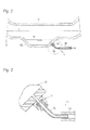
- FIG. 1 illustrates a conceptual view of an internal combustion engine 1 including the condensation water drain control mechanism.
- the internal combustion engine 1 illustrated in Fig. 1 includes an intake pipe passage 12 leading to an engine 1 and an exhaust pipe passage 13 extending from the engine 11, and a supercharger 14 is disposed between the intake pipe passage 12 and the exhaust pipe passage 13.
- the intake pipe passage 12 has an intercooler 121, a reservoir 122 and a pressure sensor 123 on the downstream side of the supercharger 14, and has a flow rate sensor 124 upstream the supercharger 14.
- the exhaust pipe passage 13 has after-treatment devices 131 and 132 on the downstream side of the supercharger 14.
- the supercharger 14 is a so-called turbocharger and has a turbine disposed in the exhaust pipe passage 13 and a compressor disposed in the intake pipe passage 12.
- the reservoir 122 is positioned on the downstream side of the intercooler 121.
- the reservoir 122 is formed in a lowered position in the intake pipe passage 12 between the downstream side of the intercooler 121 and an intake port 111 of the engine 11, preferably in an initially lowered position on the downstream side of the intercooler 121, and stores condensation water W which is condensed in the intercooler 121.
- the pressure sensor 123 is disposed in the intake pipe passage 12 on the downstream side of the intercooler 121 and detects a pressure in the intake pipe passage 12. Accordingly, the pressure sensor 123 also detects a pressure applied to the reservoir 122.
- the flow rate sensor 124 detects a flow rate of fresh air taken in the intake pipe passage 12.
- the internal combustion engine 1 illustrated in Fig. 1 includes a bypass passage 15 communicating with a portion near a bottom of the reservoir 122.
- the bypass passage 15 includes a pipe stand 151 mounted on the outside of the reservoir 122, a nozzle 152 connected to the pipe stand 151 by a flared pipe joint, a drainage pipe 153 attached to the nozzle 152 and a bypass valve 154 disposed in the middle of the drainage pipe 153.
- downstream end of the bypass passage 15 is connected to the exhaust pipe passage 13 on the downstream side of the after-treatment devices 131 and 132.
- the bypass valve 154 is controlled so as to be operated in an open state and in a closed state, and to discharge the condensation water W in any timing.
- the internal combustion engine 1 is provided with a so-called dual loop EGR (Exhaust Gas Recirculation) system and has a high-pressure EGR pipe passage 161 and a low-pressure EGR pipe passage 162 which are an example of an exhaust gas recirculation passage.
- the high-pressure EGR pipe passage 161 communicates the exhaust pipe passage 13 between an exhaust port 112 of the engine 11 and the supercharger 14 with the intake pipe passage 12 between the intercooler 121 and the intake port 111.
- the low-pressure EGR pipe passage 162 makes the exhaust pipe passage 13 on the downstream side of the supercharger 14 communicate with the intake pipe passage 12 on the upstream side of the supercharger 14.
- the high-pressure EGR pipe passage 161 includes a high-pressure EGR valve 163 in an end portion of the intake pipe passage 12 side and the low-pressure EGR pipe passage 162 includes a low-pressure EGR valve 164 in an end portion of the intake pipe passage 12 side.
- the high-pressure EGR valve 163 and the low-pressure EGR valve 164 are open, some of the exhaust gas is flowed back by the high-pressure EGR pipe passage 161 and the low-pressure EGR pipe passage 162, respectively.
- the internal combustion engine 1 includes a throttle 17 disposed in the intake pipe passage 12, an accelerator 17A adjusting an opening degree of the throttle 17 and an accelerator switch 170 detecting an on-state in which the accelerator 17A is operated and an off-state in which the accelerator 17A is not operated.
- the throttle 17 includes a high-pressure throttle 171 and a low-pressure throttle 172.
- the high-pressure throttle 171 is disposed in the intake pipe passage 12 between the reservoir 122 and the high-pressure EGR valve 163.
- the low-pressure throttle 172 is disposed in the intake pipe passage 12 on the upstream side of the low-pressure EGR valve 164.
- the pressure sensor 123, the flow rate sensor 124, the bypass valve 154, the high-pressure EGR valve 163, the low-pressure EGR valve 164, the high-pressure throttle 171, the low-pressure throttle 172, the accelerator 17A and the accelerator switch 170 are connected to a control section 18, respectively.
- the control section 18 may be provided in a part of an engine control unit (ECU) which controls the internal combustion engine 1 and may be provided independently from the ECU.
- the condensation water drain control mechanism includes at least the supercharger 14, the intercooler 121, the pressure sensor 123, the reservoir 122, the bypass passage 15, the bypass valve 154 and the control section 18. Then, the control section 18 determines a drainage state of the condensation water W in the reservoir 122, based on the change in the pressure inside the intake pipe passage 12, which is detected in the pressure sensor 123 when the bypass valve 154 is in an open state.
- a method for determining the drainage state of the condensation water W by the control section 18 is described with reference to Figs. 4 to 7 .
- Fig. 4 is a flowchart in which the control section 18 determines whether or not the condensation water W is stored in the reservoir 122. According to the flowchart, first, the bypass valve 154 is closed (S1). Next, in order to confirm whether or not the low-pressure EGR is operated, it is determined (S2) whether the low-pressure EGR valve 164 is closed.
- the control section 18 makes the bypass valve 154 to be in the open state (S5) in any timing and determines whether or not the condensation water W is stored in the reservoir 122, based on the change in the pressure which is detected by the pressure sensor 123.
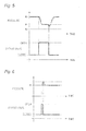
- the control section 18 sets a first pressure P 1 as a pressure in the intake pipe passage when the condensation water W is drained via the bypass passage 15 with respect to a steady pressure P 0 such as a supercharging pressure when operating the supercharger 14 or an intake pressure when performing a steady driving.
- the first pressure P 1 is a value which is obtained from data previous experiment or the like.
- the first pressure P 1 is lower than the steady pressure P 0 .
- the first pressure P 1 is higher than a second pressure P2 when the condensation water W is not stored in the reservoir 122 and the intake air is directly drained through the bypass passage 15 by an amount of flow resistance due to viscosity of the condensation water W with respect to the bypass passage 15.
- the control section 18 determines whether or not the condensation water W is drained, based on the pressure P detected in the pressure sensor 123, in other words, determines whether or not the condensation water W is stored (S6). As illustrated in Fig.
- the control section 18 makes the bypass valve 154 to be in the closed state (S7).
- the process returns to S2 which determines whether the low-pressure EGR valve 164 is closed and repeats from S2 to S7.
- the internal combustion engine 1 of the embodiment since the internal combustion engine 1 of the embodiment includes the accelerator switch 170, it is also possible to determine whether or not the condensation water W is drained with the accelerator switch 170 as a trigger.
- the pressure P of the intake pipe passage 12 is lowered by opening the bypass valve 154, the output of the engine 11 is also lowered. Accordingly, when the bypass valve 154 is open while the accelerator 17A is depressed, the output corresponding to a depressing amount of the accelerator 17A cannot be obtained.
- the low-pressure EGR valve 164 is in the open state in S2
- the bypass valve 154 is in the open state (S5).
- the accelerator switch 170 is turned on in S8, in other words, when the accelerator 17A is depressed, it is determined (S9) whether the bypass valve 154 is in the closed state.
- the bypass valve 154 is set to the closed state (S10) and the process moves to determination A (S11).
- the bypass valve 154 is in the closed state in S9, the process directly moves to the determination A (S11).
- the determination A (S11) is prepared on the assumption a case where the accelerator 17A is in a state of being depressed for a long time, for example, a case where a period until the accelerator switch 170 is turned off is long such as traveling on a highway, and a case where there is a possibility that the condensation water W is stored in the reservoir 122 beyond an allowable capacity of the volume of the reservoir 122.
- the internal combustion engine 1 of the embodiment includes a cylinder pressure sensor measuring a pressure in the cylinder of the engine 11 in addition to the pressure sensor 123 and the flow rate sensor 124.
- the control section 18 sets two conditions in the determination A (S11) for determining based on a detection value in each sensor.
- a flow rate V detected by the flow rate sensor 124 is lower than a steady flow rate V 0 corresponding to the output of the engine 11. If the condensation water W is stored in the intake pipe passage 12 beyond an allowable volume of the reservoir 122, it is expected that a cross-section of the flow passage is narrowed and then the flow rate V is decreased. Accordingly, as illustrated in Fig. 7 , when the flow rate V is lowered from the steady flow rate V 0 and then is decreased lower than a threshold value V 1 , the control section 18 makes the bypass valve 154 to be in the open state by the threshold value V 1 as the trigger (S5).
- the threshold value V 1 in the embodiment is set as a lower limit of the flow rate to maintain the operation of the engine 11.
- a value of the cylinder pressure sensor during a compression stroke of the engine 11 is abnormally increased with respect to a set pressure value.
- the control section 18 makes the bypass valve 154 to be in the open state by the value as the trigger (S5).
- Both the first condition and the second condition in the determination A mean the case where the condensation water is stored which is greater than or equal to the allowable volume beyond the volume of the reservoir 122. Accordingly, the determination A performs as storage amount detection means for detecting a storage amount of the reservoir 122.
- the storage amount detection means are configured of the pressure sensor 123, the flow rate sensor 124, the cylinder pressure sensor and the control section 18 which are contributed to the detection and the determination. Then, the storage amount detection means does not complicate the internal combustion engine in that a specialized device such as a water level sensor does not require.
- the control section 18 makes the bypass valve 154 to be in the open state (SS) by the determination A (S11) regardless of the accelerator switch 170 being turned on and the condensation water W is forcedly drained.
- the determination A (S11) when the flow rate V is the steady flow rate V 0 and the value of the cylinder pressure sensor is the set pressure value, the control section 18 determines that the condensation water W does not exceed the allowable volume of the reservoir 122 and the process repeats from S8 to S11 until the accelerator switch 170 is turned off. Then, when the accelerator switch 170 is turned off, the bypass valve 154 is set to the open state by the switch as the trigger (S5).
- the control section 18 determines (S6), based on the detected value of the pressure sensor 123.
- the pressure P is lower than or equal to the steady pressure P 0 and greater than or equal to the first pressure P 1 , in the determination A (S12), it is determined again whether the first condition or the second condition is satisfied. Any one of the first condition and the second condition being satisfied indicates that the condensation water W is not drained. Accordingly, the process returns to S6 and the detected value of the pressure sensor 123 is determined.
- the control section 18 returns to S8 and it is confirmed whether the accelerator switch 170 is turned on.
- the accelerator switch 170 is turned on, it is confirmed whether the bypass valve 154 is closed (S9). Since the output of the engine 11 is decreased when the bypass valve 154 is open, in order to prevent this, the bypass valve 154 is in the closed state (S10).
- the accelerator switch 170 is turned off in S8, the bypass valve 154 is in the open state (S5).
- first option P01 may be provided to effectively drain the condensation water W.
- first option OP1 as illustrated in Fig. 4 .
- the brake device includes at least an engine brake and a foot brake.
- the control section 18 is connected to a brake sensor 190 which is disposed in the brake pedal and detects a depressed amount to detect that the foot brake is operated.
- Signal of the brake sensor 190 may be obtained via Engine Control Unit (ECU). That the engine brake is operated may not be obtained from the ECU and may be calculated from an attenuation rate of the number of revolutions of the engine 11.
- ECU Engine Control Unit
- the control section 18 detects (S13) the operation of the engine brake or the operation of the foot brake, the high-pressure throttle 171 is throttled (S14) and the pressure in the intake pipe passage 12 on the downstream side of the intercooler 121 is increased according to the increase of the operation amount of the brake.
- the bypass valve 154 In a state where the high-pressure throttle 171 is throttled, the bypass valve 154 is in the open state (S5) so that the pressure in the intake pipe passage 12 on the downstream side of the intercooler 121, in other words, the pressure in the reservoir 122 is increased and the drainage of the condensation water W is promoted.
- the control section 18 throttles (S14) the variable vane 141 more than the position corresponding to the driving state of the engine 11 with the increase of the operation amount of the brake, similar to the above description.
- the variable vane 141 is throttled, the number of the revolutions of the turbine of the supercharger 14 is increased.
- the first option OP1 includes S13 and S14.
- the control section 18 confirms that the pressure P, detected by the pressure sensor 123, is lower than the first pressure P 1 , so that the condensation water W is drained in S6.
- the control section 18 makes the bypass valve 154 to be in the closed state in S7 and the operation of S14 is released (S15), in other words, the throttled high-pressure throttle 171 or the variable vane 141 is returned to an original state which is a position state corresponding to the output of the engine 11.
- the condensation water W is not only drained from the inside of the intake pipe passage 12 but also from the reservoir 122 by passing through S6 even though it is determined that the first condition or the second condition in the determination A is satisfied in S11 and S12. If the condensation water W is drained from the reservoir 122, the intake pipe passage 12 is not clogged with the condensation water W for a while. Accordingly, the control section 18 releases (S16) the determination of the determination A and returns to S2.
- bypass valve 154 When the accelerator switch 170 is turned on in S8 and the first condition or the second condition of the determination A is satisfied in S11, the bypass valve 154 is in the open state in S5 and then the pressure P in the intake pipe passage 12 is decreased. Accordingly, the output of the engine 11 is slightly reduced. Then, in this case, second option OP2 may be added as the control to complement the reduction of the output of the engine 11.
- the second option OP2 is provided while the pressure P is maintained between the steady pressure P 0 and the first pressure P 1 after the start of the drainage of the condensation water W in S5, in other words, while S6 and S12 are repeated until the condensation water W is discharged and then the flow rate V of the intake pipe passage 12 is recovered to the steady flow rate V 0 .
- the pressure P is increased by injecting the fuel greater than the supply amount of the fuel corresponding to the operation of the accelerator 17A from a fuel injector 20 or by throttling (S19) the variable vane 141 of the supercharger 14 in the second option OP2 so that the output of the engine 11 does not decrease.
- the control section 18 confirms (S20) whether the pressure P is increased and when the pressure P is increased more than before, the process returns to S18 and it is confirmed whether the pressure P is the steady pressure P 0 .
- the process returns to S6.
- the second option OP2 includes S18 to S20.
- the control section 18 In a case where the process passes through S19 in which a fuel injection amount is increased or the variable vane 141 is throttled, the control section 18 also releases S19 when releasing S14 in S15, after the condensation water W is drained and the bypass valve 154 is in the closed state in S7. In a case where the process passes through S19, since the determination A of S11 or S12 is also carried out, the determination of the determination A is further cleared in S16 and the process returns to S2.
- the bypass valve 154 disposed in the bypass passage 15 to drain the condensation water W is in the open state and the condensation water W can be reliably drained, based on the change in the pressure P detected by the pressure sensor 123 disposed in the intake pipe passage 12.
- the bypass valve 154 is in the closed state so that it is possible to prevent that the intake air in the intake pipe passage 12 is drained after the condensation water W is completely drained.
- the bypass passage 15 when the downstream end of the bypass passage 15 is connected to the exhaust pipe passage 13, the bypass passage 15 communicates with the downstream side of the position in which the after-treatment devices 131 and 132 are provided.
- the after-treatment devices 131 and 132 have a built-in catalyst which treats chemical substances such as NOx, SOx and HC in the exhaust gas.
- the catalyst can perform catalytic reaction by being heated to an activation temperature by the heat of the exhaust gas.
- the bypass passage 15 communicates with the upstream side of the after-treatment devices 131 and 132 and the condensation water W is drained to the upstream side of the catalyst, the heat of the exhaust gas is consumed to vaporize the condensation water W and the temperature of the catalyst is decreased.
- the activation temperature of the catalyst is decreased, the catalytic reaction is suppressed and original functions cannot be performed.
- the catalyst is made of ceramics, it may be broken by quenching with the condensation water W.
- the condensation water drain control mechanism of the invention since the bypass passage 15 communicates with the downstream side of the after-treatment device 132, the catalytic reaction is not inhibited.
- the pressure sensor 123 detects that the pressure P is lower than or equal to the first pressure P 1 and makes the bypass valve 154 to be in the closed state immediately so that there is no concern that some of the exhaust gas, which is flowed back to the intake pipe passage 12 using the low-pressure EGR pipe passage 162, is drained through the bypass passage 15.
- the control is performed whether or not the condensation water W is drained in a case where the low-pressure EGR valve 164 is not closed, in other words, where the low-pressure EGR is operated.
- the invention also includes a configuration in which S2 in flowchart illustrated in Fig. 4 is omitted and the bypass valve 154 is in the open state and then presence or absence of the condensation water W is confirmed regardless of whether or not the low-pressure EGR being operated. In this case, in S2 of the flowchart illustrated in Fig. 4 , it is determined whether or not the drainage of the condensation water is necessary.
- the process may go to S3 and when it is necessary, the process may go to S5, respectively. It may be determined whether or not the drainage of the condensation water is necessary, based on the elapsed time from staring of the internal combustion engine 1 or the time when the accelerator is continuously depressed.
Landscapes
- Engineering & Computer Science (AREA)
- Physics & Mathematics (AREA)
- Thermal Sciences (AREA)
- Chemical & Material Sciences (AREA)
- Combustion & Propulsion (AREA)
- Mechanical Engineering (AREA)
- General Engineering & Computer Science (AREA)
- Supercharger (AREA)
- Output Control And Ontrol Of Special Type Engine (AREA)
- Exhaust-Gas Circulating Devices (AREA)
Applications Claiming Priority (1)
| Application Number | Priority Date | Filing Date | Title |
|---|---|---|---|
| JP2012129996A JP5962233B2 (ja) | 2012-06-07 | 2012-06-07 | 凝縮水排出制御機構 |
Publications (3)
| Publication Number | Publication Date |
|---|---|
| EP2672087A2 true EP2672087A2 (de) | 2013-12-11 |
| EP2672087A3 EP2672087A3 (de) | 2015-04-22 |
| EP2672087B1 EP2672087B1 (de) | 2017-03-01 |
Family
ID=48625767
Family Applications (1)
| Application Number | Title | Priority Date | Filing Date |
|---|---|---|---|
| EP13170680.6A Not-in-force EP2672087B1 (de) | 2012-06-07 | 2013-06-05 | Kondensationswasserablass-Steuermechanismus |
Country Status (3)
| Country | Link |
|---|---|
| EP (1) | EP2672087B1 (de) |
| JP (1) | JP5962233B2 (de) |
| CN (1) | CN103485943B (de) |
Cited By (5)
| Publication number | Priority date | Publication date | Assignee | Title |
|---|---|---|---|---|
| DE102015001663A1 (de) * | 2015-02-10 | 2016-08-11 | Man Diesel & Turbo Se | Brennkraftmaschine und Verfahren zum Betreiben derselben |
| DE102015112185B4 (de) | 2014-08-06 | 2019-12-24 | Denso Corporation | Ventilvorrichtung |
| US10774793B2 (en) | 2017-08-25 | 2020-09-15 | Mazda Motor Corporation | Intake and exhaust device for automotive engine |
| CN116838504A (zh) * | 2023-06-30 | 2023-10-03 | 潍柴动力股份有限公司 | 电磁阀控制方法、系统、装置、设备及存储介质 |
| CN119122713A (zh) * | 2024-09-09 | 2024-12-13 | 中国第一汽车股份有限公司 | 发动机的进排气系统及其控制方法 |
Families Citing this family (7)
| Publication number | Priority date | Publication date | Assignee | Title |
|---|---|---|---|---|
| JP6455581B1 (ja) * | 2017-11-17 | 2019-01-23 | マツダ株式会社 | エンジンの制御装置及びエンジンの制御方法 |
| KR101953098B1 (ko) * | 2018-05-15 | 2019-02-28 | 구진호 | 내연기관용 인터쿨러의 응축수 배출장치 |
| CN108757240A (zh) * | 2018-06-05 | 2018-11-06 | 潍柴动力股份有限公司 | 一种柴油发动机进气系统及热管理方法、装置 |
| CN112051755A (zh) * | 2020-09-14 | 2020-12-08 | 潍柴动力股份有限公司 | 一种电控放水阀的控制方法及控制装置 |
| CN112709854B (zh) * | 2021-01-04 | 2023-01-06 | 潍柴动力股份有限公司 | 电控放水阀控制方法、装置、电子设备及存储介质 |
| CN114738079B (zh) * | 2022-03-16 | 2023-10-20 | 潍柴动力股份有限公司 | 一种发动机气体循环系统及其控制方法和车辆 |
| CN115420505B (zh) * | 2022-08-24 | 2024-08-23 | 东风汽车集团股份有限公司 | 一种发动机的废气再循环系统的试验方法和试验装置 |
Citations (4)
| Publication number | Priority date | Publication date | Assignee | Title |
|---|---|---|---|---|
| JP2000130172A (ja) | 1998-10-29 | 2000-05-09 | Nissan Diesel Motor Co Ltd | アフタクーラの結露水排出装置 |
| JP2002303146A (ja) | 2001-04-06 | 2002-10-18 | Mitsubishi Motors Corp | 過給機付内燃機関 |
| JP2010096050A (ja) | 2008-10-15 | 2010-04-30 | Denso Corp | 過給システムの異常検出装置 |
| JP2010242640A (ja) | 2009-04-07 | 2010-10-28 | Toyota Motor Corp | 内燃機関の吸気漏れ検出システム |
Family Cites Families (11)
| Publication number | Priority date | Publication date | Assignee | Title |
|---|---|---|---|---|
| CH582827A5 (de) * | 1974-09-24 | 1976-12-15 | Sulzer Ag | |
| JP4661618B2 (ja) * | 2006-02-08 | 2011-03-30 | トヨタ自動車株式会社 | 過給機付内燃機関の吸気冷却装置 |
| JP2009215904A (ja) * | 2008-03-07 | 2009-09-24 | Toyota Motor Corp | 内燃機関のインタークーラ凝縮水排出装置 |
| FR2940366B1 (fr) * | 2008-12-22 | 2011-02-18 | Renault Sas | Dispositif de traitement d'un melange gazeux pour moteur a combustion interne |
| US8191366B2 (en) * | 2009-03-13 | 2012-06-05 | Denso International America, Inc. | Charge air cooler condensate separation and dispersion system |
| FR2957980A1 (fr) * | 2010-03-24 | 2011-09-30 | Renault Sas | Circuit d'admission d'un moteur a combustion interne |
| FR2959779A1 (fr) * | 2010-05-07 | 2011-11-11 | Peugeot Citroen Automobiles Sa | Refroidisseur d'air de suralimentation, systeme de gestion des condensats et procede mis en œuvre par un tel systeme |
| JP2011241797A (ja) * | 2010-05-21 | 2011-12-01 | Hino Motors Ltd | エンジンの吸気冷却装置 |
| US8371119B2 (en) * | 2010-09-08 | 2013-02-12 | Caterpillar Inc. | Drain valve for an air intake system of a machine |
| KR101628095B1 (ko) * | 2010-10-18 | 2016-06-08 | 현대자동차 주식회사 | 저압 egr시스템 제어장치 및 방법 |
| JP2012087718A (ja) * | 2010-10-21 | 2012-05-10 | Mitsubishi Heavy Ind Ltd | エンジン給気冷却装置及びこれを備えたエンジン |
-
2012
- 2012-06-07 JP JP2012129996A patent/JP5962233B2/ja not_active Expired - Fee Related
-
2013
- 2013-06-05 EP EP13170680.6A patent/EP2672087B1/de not_active Not-in-force
- 2013-06-06 CN CN201310224744.7A patent/CN103485943B/zh not_active Expired - Fee Related
Patent Citations (4)
| Publication number | Priority date | Publication date | Assignee | Title |
|---|---|---|---|---|
| JP2000130172A (ja) | 1998-10-29 | 2000-05-09 | Nissan Diesel Motor Co Ltd | アフタクーラの結露水排出装置 |
| JP2002303146A (ja) | 2001-04-06 | 2002-10-18 | Mitsubishi Motors Corp | 過給機付内燃機関 |
| JP2010096050A (ja) | 2008-10-15 | 2010-04-30 | Denso Corp | 過給システムの異常検出装置 |
| JP2010242640A (ja) | 2009-04-07 | 2010-10-28 | Toyota Motor Corp | 内燃機関の吸気漏れ検出システム |
Cited By (5)
| Publication number | Priority date | Publication date | Assignee | Title |
|---|---|---|---|---|
| DE102015112185B4 (de) | 2014-08-06 | 2019-12-24 | Denso Corporation | Ventilvorrichtung |
| DE102015001663A1 (de) * | 2015-02-10 | 2016-08-11 | Man Diesel & Turbo Se | Brennkraftmaschine und Verfahren zum Betreiben derselben |
| US10774793B2 (en) | 2017-08-25 | 2020-09-15 | Mazda Motor Corporation | Intake and exhaust device for automotive engine |
| CN116838504A (zh) * | 2023-06-30 | 2023-10-03 | 潍柴动力股份有限公司 | 电磁阀控制方法、系统、装置、设备及存储介质 |
| CN119122713A (zh) * | 2024-09-09 | 2024-12-13 | 中国第一汽车股份有限公司 | 发动机的进排气系统及其控制方法 |
Also Published As
| Publication number | Publication date |
|---|---|
| JP2013253561A (ja) | 2013-12-19 |
| CN103485943A (zh) | 2014-01-01 |
| JP5962233B2 (ja) | 2016-08-03 |
| EP2672087B1 (de) | 2017-03-01 |
| CN103485943B (zh) | 2016-02-03 |
| EP2672087A3 (de) | 2015-04-22 |
Similar Documents
| Publication | Publication Date | Title |
|---|---|---|
| EP2672087B1 (de) | Kondensationswasserablass-Steuermechanismus | |
| US7801669B2 (en) | Exhaust gas control system for internal combustion engine | |
| US8307629B2 (en) | Control method of exhaust emission purification system and exhaust emission purification system | |
| RU2620889C2 (ru) | Способ эксплуатации двигателя и система двигателя | |
| US9464586B2 (en) | Exhaust gas recirculation system of engine | |
| EP3025033B1 (de) | Abgasemissionssteuerungssystem für einen verbrennungsmotor und steuerungsverfahren für das abgasemissionssteuerungssystem | |
| US20070131207A1 (en) | Exhaust gas recirculation in diesel engine | |
| US20100204905A1 (en) | Control unit of diesel engine | |
| WO2009107175A1 (ja) | コモンレールシステムの異常時制御装置 | |
| EP3093465B1 (de) | Steuerungsvorrichtung für verbrennungsmotor | |
| EP3018332A1 (de) | Verarbeitungsvorrichtung für kondensiertes wasser eines verbrennungsmotors | |
| US11530631B2 (en) | Engine oil state control device | |
| US20090044517A1 (en) | Exhaust gas purification system for an internal combustion engine | |
| WO2015097520A1 (en) | Exhaust gas control device for internal combustion engine mounted on vehicle | |
| EP2202400A2 (de) | Fahrzeugmotorleistungssteuerung | |
| JP6589365B2 (ja) | 排出ガス浄化システム | |
| JP2005264821A (ja) | 内燃機関の排気還流システム | |
| JP2009121362A (ja) | 内燃機関のフィルタ再生制御装置 | |
| EP3524786B1 (de) | Regenerationssteuerungsvorrichtung für eine abgasreinigungsvorrichtung | |
| JP6551677B2 (ja) | 内燃機関の凝縮水排出装置 | |
| JP2017075554A (ja) | 内燃機関の凝縮水排出装置 | |
| JP5370307B2 (ja) | 油圧制御装置 | |
| JP2017075553A (ja) | 内燃機関の制御装置 | |
| JP7420044B2 (ja) | 内燃機関の冷却システム | |
| JP6237158B2 (ja) | 内燃機関の排水制御装置 |
Legal Events
| Date | Code | Title | Description |
|---|---|---|---|
| PUAI | Public reference made under article 153(3) epc to a published international application that has entered the european phase |
Free format text: ORIGINAL CODE: 0009012 |
|
| 17P | Request for examination filed |
Effective date: 20130704 |
|
| AK | Designated contracting states |
Kind code of ref document: A2 Designated state(s): AL AT BE BG CH CY CZ DE DK EE ES FI FR GB GR HR HU IE IS IT LI LT LU LV MC MK MT NL NO PL PT RO RS SE SI SK SM TR |
|
| AX | Request for extension of the european patent |
Extension state: BA ME |
|
| PUAL | Search report despatched |
Free format text: ORIGINAL CODE: 0009013 |
|
| AK | Designated contracting states |
Kind code of ref document: A3 Designated state(s): AL AT BE BG CH CY CZ DE DK EE ES FI FR GB GR HR HU IE IS IT LI LT LU LV MC MK MT NL NO PL PT RO RS SE SI SK SM TR |
|
| AX | Request for extension of the european patent |
Extension state: BA ME |
|
| RIC1 | Information provided on ipc code assigned before grant |
Ipc: F02B 29/04 20060101AFI20150318BHEP Ipc: F02M 25/07 20060101ALI20150318BHEP Ipc: F28F 17/00 20060101ALI20150318BHEP |
|
| RIC1 | Information provided on ipc code assigned before grant |
Ipc: F02M 26/05 20160101ALI20160217BHEP Ipc: F02B 29/04 20060101AFI20160217BHEP Ipc: F28F 17/00 20060101ALI20160217BHEP Ipc: F02M 26/06 20160101ALI20160217BHEP |
|
| GRAP | Despatch of communication of intention to grant a patent |
Free format text: ORIGINAL CODE: EPIDOSNIGR1 |
|
| INTG | Intention to grant announced |
Effective date: 20160401 |
|
| GRAJ | Information related to disapproval of communication of intention to grant by the applicant or resumption of examination proceedings by the epo deleted |
Free format text: ORIGINAL CODE: EPIDOSDIGR1 |
|
| GRAL | Information related to payment of fee for publishing/printing deleted |
Free format text: ORIGINAL CODE: EPIDOSDIGR3 |
|
| GRAS | Grant fee paid |
Free format text: ORIGINAL CODE: EPIDOSNIGR3 |
|
| GRAJ | Information related to disapproval of communication of intention to grant by the applicant or resumption of examination proceedings by the epo deleted |
Free format text: ORIGINAL CODE: EPIDOSDIGR1 |
|
| GRAP | Despatch of communication of intention to grant a patent |
Free format text: ORIGINAL CODE: EPIDOSNIGR1 |
|
| INTC | Intention to grant announced (deleted) | ||
| GRAP | Despatch of communication of intention to grant a patent |
Free format text: ORIGINAL CODE: EPIDOSNIGR1 |
|
| INTG | Intention to grant announced |
Effective date: 20160922 |
|
| INTG | Intention to grant announced |
Effective date: 20160930 |
|
| GRAA | (expected) grant |
Free format text: ORIGINAL CODE: 0009210 |
|
| AK | Designated contracting states |
Kind code of ref document: B1 Designated state(s): AL AT BE BG CH CY CZ DE DK EE ES FI FR GB GR HR HU IE IS IT LI LT LU LV MC MK MT NL NO PL PT RO RS SE SI SK SM TR |
|
| REG | Reference to a national code |
Ref country code: GB Ref legal event code: FG4D |
|
| REG | Reference to a national code |
Ref country code: CH Ref legal event code: EP Ref country code: AT Ref legal event code: REF Ref document number: 871654 Country of ref document: AT Kind code of ref document: T Effective date: 20170315 |
|
| REG | Reference to a national code |
Ref country code: IE Ref legal event code: FG4D |
|
| REG | Reference to a national code |
Ref country code: DE Ref legal event code: R096 Ref document number: 602013017868 Country of ref document: DE |
|
| REG | Reference to a national code |
Ref country code: FR Ref legal event code: PLFP Year of fee payment: 5 |
|
| REG | Reference to a national code |
Ref country code: NL Ref legal event code: MP Effective date: 20170301 |
|
| REG | Reference to a national code |
Ref country code: LT Ref legal event code: MG4D |
|
| REG | Reference to a national code |
Ref country code: AT Ref legal event code: MK05 Ref document number: 871654 Country of ref document: AT Kind code of ref document: T Effective date: 20170301 |
|
| PG25 | Lapsed in a contracting state [announced via postgrant information from national office to epo] |
Ref country code: NO Free format text: LAPSE BECAUSE OF FAILURE TO SUBMIT A TRANSLATION OF THE DESCRIPTION OR TO PAY THE FEE WITHIN THE PRESCRIBED TIME-LIMIT Effective date: 20170601 Ref country code: GR Free format text: LAPSE BECAUSE OF FAILURE TO SUBMIT A TRANSLATION OF THE DESCRIPTION OR TO PAY THE FEE WITHIN THE PRESCRIBED TIME-LIMIT Effective date: 20170602 Ref country code: FI Free format text: LAPSE BECAUSE OF FAILURE TO SUBMIT A TRANSLATION OF THE DESCRIPTION OR TO PAY THE FEE WITHIN THE PRESCRIBED TIME-LIMIT Effective date: 20170301 Ref country code: LT Free format text: LAPSE BECAUSE OF FAILURE TO SUBMIT A TRANSLATION OF THE DESCRIPTION OR TO PAY THE FEE WITHIN THE PRESCRIBED TIME-LIMIT Effective date: 20170301 Ref country code: HR Free format text: LAPSE BECAUSE OF FAILURE TO SUBMIT A TRANSLATION OF THE DESCRIPTION OR TO PAY THE FEE WITHIN THE PRESCRIBED TIME-LIMIT Effective date: 20170301 |
|
| PG25 | Lapsed in a contracting state [announced via postgrant information from national office to epo] |
Ref country code: BG Free format text: LAPSE BECAUSE OF FAILURE TO SUBMIT A TRANSLATION OF THE DESCRIPTION OR TO PAY THE FEE WITHIN THE PRESCRIBED TIME-LIMIT Effective date: 20170601 Ref country code: LV Free format text: LAPSE BECAUSE OF FAILURE TO SUBMIT A TRANSLATION OF THE DESCRIPTION OR TO PAY THE FEE WITHIN THE PRESCRIBED TIME-LIMIT Effective date: 20170301 Ref country code: SE Free format text: LAPSE BECAUSE OF FAILURE TO SUBMIT A TRANSLATION OF THE DESCRIPTION OR TO PAY THE FEE WITHIN THE PRESCRIBED TIME-LIMIT Effective date: 20170301 Ref country code: RS Free format text: LAPSE BECAUSE OF FAILURE TO SUBMIT A TRANSLATION OF THE DESCRIPTION OR TO PAY THE FEE WITHIN THE PRESCRIBED TIME-LIMIT Effective date: 20170301 Ref country code: AT Free format text: LAPSE BECAUSE OF FAILURE TO SUBMIT A TRANSLATION OF THE DESCRIPTION OR TO PAY THE FEE WITHIN THE PRESCRIBED TIME-LIMIT Effective date: 20170301 Ref country code: ES Free format text: LAPSE BECAUSE OF FAILURE TO SUBMIT A TRANSLATION OF THE DESCRIPTION OR TO PAY THE FEE WITHIN THE PRESCRIBED TIME-LIMIT Effective date: 20170301 |
|
| PG25 | Lapsed in a contracting state [announced via postgrant information from national office to epo] |
Ref country code: NL Free format text: LAPSE BECAUSE OF FAILURE TO SUBMIT A TRANSLATION OF THE DESCRIPTION OR TO PAY THE FEE WITHIN THE PRESCRIBED TIME-LIMIT Effective date: 20170301 |
|
| PG25 | Lapsed in a contracting state [announced via postgrant information from national office to epo] |
Ref country code: SK Free format text: LAPSE BECAUSE OF FAILURE TO SUBMIT A TRANSLATION OF THE DESCRIPTION OR TO PAY THE FEE WITHIN THE PRESCRIBED TIME-LIMIT Effective date: 20170301 Ref country code: RO Free format text: LAPSE BECAUSE OF FAILURE TO SUBMIT A TRANSLATION OF THE DESCRIPTION OR TO PAY THE FEE WITHIN THE PRESCRIBED TIME-LIMIT Effective date: 20170301 Ref country code: IT Free format text: LAPSE BECAUSE OF FAILURE TO SUBMIT A TRANSLATION OF THE DESCRIPTION OR TO PAY THE FEE WITHIN THE PRESCRIBED TIME-LIMIT Effective date: 20170301 Ref country code: EE Free format text: LAPSE BECAUSE OF FAILURE TO SUBMIT A TRANSLATION OF THE DESCRIPTION OR TO PAY THE FEE WITHIN THE PRESCRIBED TIME-LIMIT Effective date: 20170301 Ref country code: CZ Free format text: LAPSE BECAUSE OF FAILURE TO SUBMIT A TRANSLATION OF THE DESCRIPTION OR TO PAY THE FEE WITHIN THE PRESCRIBED TIME-LIMIT Effective date: 20170301 |
|
| PG25 | Lapsed in a contracting state [announced via postgrant information from national office to epo] |
Ref country code: PL Free format text: LAPSE BECAUSE OF FAILURE TO SUBMIT A TRANSLATION OF THE DESCRIPTION OR TO PAY THE FEE WITHIN THE PRESCRIBED TIME-LIMIT Effective date: 20170301 Ref country code: PT Free format text: LAPSE BECAUSE OF FAILURE TO SUBMIT A TRANSLATION OF THE DESCRIPTION OR TO PAY THE FEE WITHIN THE PRESCRIBED TIME-LIMIT Effective date: 20170703 Ref country code: SM Free format text: LAPSE BECAUSE OF FAILURE TO SUBMIT A TRANSLATION OF THE DESCRIPTION OR TO PAY THE FEE WITHIN THE PRESCRIBED TIME-LIMIT Effective date: 20170301 Ref country code: IS Free format text: LAPSE BECAUSE OF FAILURE TO SUBMIT A TRANSLATION OF THE DESCRIPTION OR TO PAY THE FEE WITHIN THE PRESCRIBED TIME-LIMIT Effective date: 20170701 |
|
| REG | Reference to a national code |
Ref country code: DE Ref legal event code: R097 Ref document number: 602013017868 Country of ref document: DE |
|
| PLBE | No opposition filed within time limit |
Free format text: ORIGINAL CODE: 0009261 |
|
| STAA | Information on the status of an ep patent application or granted ep patent |
Free format text: STATUS: NO OPPOSITION FILED WITHIN TIME LIMIT |
|
| PG25 | Lapsed in a contracting state [announced via postgrant information from national office to epo] |
Ref country code: DK Free format text: LAPSE BECAUSE OF FAILURE TO SUBMIT A TRANSLATION OF THE DESCRIPTION OR TO PAY THE FEE WITHIN THE PRESCRIBED TIME-LIMIT Effective date: 20170301 Ref country code: MC Free format text: LAPSE BECAUSE OF FAILURE TO SUBMIT A TRANSLATION OF THE DESCRIPTION OR TO PAY THE FEE WITHIN THE PRESCRIBED TIME-LIMIT Effective date: 20170301 |
|
| REG | Reference to a national code |
Ref country code: CH Ref legal event code: PL |
|
| 26N | No opposition filed |
Effective date: 20171204 |
|
| GBPC | Gb: european patent ceased through non-payment of renewal fee |
Effective date: 20170605 |
|
| PG25 | Lapsed in a contracting state [announced via postgrant information from national office to epo] |
Ref country code: SI Free format text: LAPSE BECAUSE OF FAILURE TO SUBMIT A TRANSLATION OF THE DESCRIPTION OR TO PAY THE FEE WITHIN THE PRESCRIBED TIME-LIMIT Effective date: 20170301 |
|
| REG | Reference to a national code |
Ref country code: IE Ref legal event code: MM4A |
|
| PG25 | Lapsed in a contracting state [announced via postgrant information from national office to epo] |
Ref country code: LI Free format text: LAPSE BECAUSE OF NON-PAYMENT OF DUE FEES Effective date: 20170630 Ref country code: GB Free format text: LAPSE BECAUSE OF NON-PAYMENT OF DUE FEES Effective date: 20170605 Ref country code: CH Free format text: LAPSE BECAUSE OF NON-PAYMENT OF DUE FEES Effective date: 20170630 Ref country code: LU Free format text: LAPSE BECAUSE OF NON-PAYMENT OF DUE FEES Effective date: 20170605 Ref country code: IE Free format text: LAPSE BECAUSE OF NON-PAYMENT OF DUE FEES Effective date: 20170605 |
|
| REG | Reference to a national code |
Ref country code: FR Ref legal event code: PLFP Year of fee payment: 6 |
|
| REG | Reference to a national code |
Ref country code: BE Ref legal event code: MM Effective date: 20170630 |
|
| PG25 | Lapsed in a contracting state [announced via postgrant information from national office to epo] |
Ref country code: BE Free format text: LAPSE BECAUSE OF NON-PAYMENT OF DUE FEES Effective date: 20170630 |
|
| PG25 | Lapsed in a contracting state [announced via postgrant information from national office to epo] |
Ref country code: MT Free format text: LAPSE BECAUSE OF NON-PAYMENT OF DUE FEES Effective date: 20170605 |
|
| PG25 | Lapsed in a contracting state [announced via postgrant information from national office to epo] |
Ref country code: HU Free format text: LAPSE BECAUSE OF FAILURE TO SUBMIT A TRANSLATION OF THE DESCRIPTION OR TO PAY THE FEE WITHIN THE PRESCRIBED TIME-LIMIT; INVALID AB INITIO Effective date: 20130605 |
|
| PG25 | Lapsed in a contracting state [announced via postgrant information from national office to epo] |
Ref country code: CY Free format text: LAPSE BECAUSE OF NON-PAYMENT OF DUE FEES Effective date: 20170301 |
|
| PG25 | Lapsed in a contracting state [announced via postgrant information from national office to epo] |
Ref country code: MK Free format text: LAPSE BECAUSE OF FAILURE TO SUBMIT A TRANSLATION OF THE DESCRIPTION OR TO PAY THE FEE WITHIN THE PRESCRIBED TIME-LIMIT Effective date: 20170301 |
|
| PG25 | Lapsed in a contracting state [announced via postgrant information from national office to epo] |
Ref country code: TR Free format text: LAPSE BECAUSE OF FAILURE TO SUBMIT A TRANSLATION OF THE DESCRIPTION OR TO PAY THE FEE WITHIN THE PRESCRIBED TIME-LIMIT Effective date: 20170301 |
|
| PG25 | Lapsed in a contracting state [announced via postgrant information from national office to epo] |
Ref country code: AL Free format text: LAPSE BECAUSE OF FAILURE TO SUBMIT A TRANSLATION OF THE DESCRIPTION OR TO PAY THE FEE WITHIN THE PRESCRIBED TIME-LIMIT Effective date: 20170301 |
|
| PGFP | Annual fee paid to national office [announced via postgrant information from national office to epo] |
Ref country code: FR Payment date: 20200512 Year of fee payment: 8 Ref country code: DE Payment date: 20200527 Year of fee payment: 8 |
|
| REG | Reference to a national code |
Ref country code: DE Ref legal event code: R119 Ref document number: 602013017868 Country of ref document: DE |
|
| PG25 | Lapsed in a contracting state [announced via postgrant information from national office to epo] |
Ref country code: DE Free format text: LAPSE BECAUSE OF NON-PAYMENT OF DUE FEES Effective date: 20220101 |
|
| PG25 | Lapsed in a contracting state [announced via postgrant information from national office to epo] |
Ref country code: FR Free format text: LAPSE BECAUSE OF NON-PAYMENT OF DUE FEES Effective date: 20210630 |