EP2672110A2 - Commande d'un système d'énergie éolienne - Google Patents
Commande d'un système d'énergie éolienne Download PDFInfo
- Publication number
- EP2672110A2 EP2672110A2 EP13165208.3A EP13165208A EP2672110A2 EP 2672110 A2 EP2672110 A2 EP 2672110A2 EP 13165208 A EP13165208 A EP 13165208A EP 2672110 A2 EP2672110 A2 EP 2672110A2
- Authority
- EP
- European Patent Office
- Prior art keywords
- wind energy
- data object
- energy device
- wind
- energy system
- Prior art date
- Legal status (The legal status is an assumption and is not a legal conclusion. Google has not performed a legal analysis and makes no representation as to the accuracy of the status listed.)
- Withdrawn
Links
Images


Classifications
-
- F—MECHANICAL ENGINEERING; LIGHTING; HEATING; WEAPONS; BLASTING
- F03—MACHINES OR ENGINES FOR LIQUIDS; WIND, SPRING, OR WEIGHT MOTORS; PRODUCING MECHANICAL POWER OR A REACTIVE PROPULSIVE THRUST, NOT OTHERWISE PROVIDED FOR
- F03D—WIND MOTORS
- F03D7/00—Controlling wind motors
- F03D7/02—Controlling wind motors the wind motors having rotation axis substantially parallel to the air flow entering the rotor
- F03D7/04—Automatic control; Regulation
- F03D7/042—Automatic control; Regulation by means of an electrical or electronic controller
- F03D7/048—Automatic control; Regulation by means of an electrical or electronic controller controlling wind farms
-
- F—MECHANICAL ENGINEERING; LIGHTING; HEATING; WEAPONS; BLASTING
- F03—MACHINES OR ENGINES FOR LIQUIDS; WIND, SPRING, OR WEIGHT MOTORS; PRODUCING MECHANICAL POWER OR A REACTIVE PROPULSIVE THRUST, NOT OTHERWISE PROVIDED FOR
- F03D—WIND MOTORS
- F03D7/00—Controlling wind motors
- F03D7/02—Controlling wind motors the wind motors having rotation axis substantially parallel to the air flow entering the rotor
- F03D7/04—Automatic control; Regulation
- F03D7/042—Automatic control; Regulation by means of an electrical or electronic controller
- F03D7/047—Automatic control; Regulation by means of an electrical or electronic controller characterised by the controller architecture, e.g. multiple processors or data communications
-
- G—PHYSICS
- G05—CONTROLLING; REGULATING
- G05B—CONTROL OR REGULATING SYSTEMS IN GENERAL; FUNCTIONAL ELEMENTS OF SUCH SYSTEMS; MONITORING OR TESTING ARRANGEMENTS FOR SUCH SYSTEMS OR ELEMENTS
- G05B15/00—Systems controlled by a computer
- G05B15/02—Systems controlled by a computer electric
-
- F—MECHANICAL ENGINEERING; LIGHTING; HEATING; WEAPONS; BLASTING
- F05—INDEXING SCHEMES RELATING TO ENGINES OR PUMPS IN VARIOUS SUBCLASSES OF CLASSES F01-F04
- F05B—INDEXING SCHEME RELATING TO WIND, SPRING, WEIGHT, INERTIA OR LIKE MOTORS, TO MACHINES OR ENGINES FOR LIQUIDS COVERED BY SUBCLASSES F03B, F03D AND F03G
- F05B2240/00—Components
- F05B2240/90—Mounting on supporting structures or systems
- F05B2240/95—Mounting on supporting structures or systems offshore
-
- G—PHYSICS
- G05—CONTROLLING; REGULATING
- G05B—CONTROL OR REGULATING SYSTEMS IN GENERAL; FUNCTIONAL ELEMENTS OF SUCH SYSTEMS; MONITORING OR TESTING ARRANGEMENTS FOR SUCH SYSTEMS OR ELEMENTS
- G05B2219/00—Program-control systems
- G05B2219/20—Pc systems
- G05B2219/26—Pc applications
- G05B2219/2619—Wind turbines
-
- G—PHYSICS
- G05—CONTROLLING; REGULATING
- G05B—CONTROL OR REGULATING SYSTEMS IN GENERAL; FUNCTIONAL ELEMENTS OF SUCH SYSTEMS; MONITORING OR TESTING ARRANGEMENTS FOR SUCH SYSTEMS OR ELEMENTS
- G05B2219/00—Program-control systems
- G05B2219/30—Nc systems
- G05B2219/32—Operator till task planning
- G05B2219/32404—Scada supervisory control and data acquisition
-
- Y—GENERAL TAGGING OF NEW TECHNOLOGICAL DEVELOPMENTS; GENERAL TAGGING OF CROSS-SECTIONAL TECHNOLOGIES SPANNING OVER SEVERAL SECTIONS OF THE IPC; TECHNICAL SUBJECTS COVERED BY FORMER USPC CROSS-REFERENCE ART COLLECTIONS [XRACs] AND DIGESTS
- Y02—TECHNOLOGIES OR APPLICATIONS FOR MITIGATION OR ADAPTATION AGAINST CLIMATE CHANGE
- Y02E—REDUCTION OF GREENHOUSE GAS [GHG] EMISSIONS, RELATED TO ENERGY GENERATION, TRANSMISSION OR DISTRIBUTION
- Y02E10/00—Energy generation through renewable energy sources
- Y02E10/70—Wind energy
- Y02E10/72—Wind turbines with rotation axis in wind direction
-
- Y—GENERAL TAGGING OF NEW TECHNOLOGICAL DEVELOPMENTS; GENERAL TAGGING OF CROSS-SECTIONAL TECHNOLOGIES SPANNING OVER SEVERAL SECTIONS OF THE IPC; TECHNICAL SUBJECTS COVERED BY FORMER USPC CROSS-REFERENCE ART COLLECTIONS [XRACs] AND DIGESTS
- Y02—TECHNOLOGIES OR APPLICATIONS FOR MITIGATION OR ADAPTATION AGAINST CLIMATE CHANGE
- Y02E—REDUCTION OF GREENHOUSE GAS [GHG] EMISSIONS, RELATED TO ENERGY GENERATION, TRANSMISSION OR DISTRIBUTION
- Y02E10/00—Energy generation through renewable energy sources
- Y02E10/70—Wind energy
- Y02E10/727—Offshore wind turbines
Definitions
- the invention relates to a wind energy system, in particular an offshore wind energy system comprising at least one wind energy device and at least one connected by a communication network with the wind energy device headquarters. Moreover, the invention relates to a method for controlling a wind energy system and a computer program for carrying out the method.
- a wind turbine converts the kinetic energy of the wind into electrical energy by means of a rotor and a generator.
- a wind energy system can be formed from several wind turbines.
- the wind turbines can be set up especially in areas with high wind probability and intensity.
- a wind energy system may include a variety of different wind energy facilities.
- a particular problem is that a wind energy system, in contrast to a conventional power plant, such as a coal-fired power plant, usually composed of a variety of wind energy facilities of different manufacturers and providers.
- a wind energy system in contrast to a conventional power plant, such as a coal-fired power plant, usually composed of a variety of wind energy facilities of different manufacturers and providers.
- the integration Such wind energy devices in a wind energy system, which can be controlled from a remote center, therefore, high demands on the control structures with it.
- a wind energy system in which the wind energy devices can be controlled from one workstation.
- a workplace is connected here via a communication network with the wind energy facilities.
- SCADA Supervisory Control and Data Acquisition
- This component forms an interface between the components of the wind energy device and the communication network, so that a communication with the workplace is possible.
- each wind energy device must be equipped with at least one additional and specially adapted component, so that a remote control of the wind energy system is possible.
- the invention is therefore based on the object to provide a wind energy system and a method for controlling a wind energy system, which allows in a simple manner reliable control of a wind energy system, in particular an offshore wind energy system.
- the object is achieved in a wind energy system, in particular an offshore wind energy system according to claim 1.
- the wind energy system comprises at least one wind energy device.
- the wind energy system comprises at least one central office connected to the wind energy facility by a communication network.
- the center has at least one data object generator.
- the data object generator is configured to generate at least one data object by mapping the wind energy device in the center.
- the center has at least one control device.
- the control device is set up to control the wind energy device as a function of the data object.
- a reliable and simple control of a wind energy system can be provided by at least one wind energy device is imaged as a virtual object in the center and controlled by the virtual object, the real wind energy device.
- the entire wind energy system can be virtually mapped.
- all wind energy devices can preferably be imaged as virtual objects in the central office.
- the wind energy system or the wind farm may have at least one, preferably a plurality of wind energy devices.
- a remote control of the at least one wind energy device can be provided in particular a remote center.
- the center may, for example, have suitable data facilities, such as computers.
- the center may preferably be an onshore center, while the wind energy facilities may be offshore wind energy facilities.
- the center may be provided for controlling at least one wind energy system, preferably of a plurality of wind energy systems.
- the control center can be a central control room.
- a communication network For communication of the control center with the at least one wind energy device, a communication network is provided.
- communication channels in the communication network wireless and / or wired communication channels can be used.
- all wind energy devices can communicate directly or indirectly, for example via a further wind energy device, with the control center.
- a reliable and at the same time simple control of at least one wind energy device can be achieved if the at least one wind energy device is available in the center as a mapped data object.
- all wind energy devices can each be imaged as a data object.
- a data object represents the virtual image of a wind energy device, in particular the technical characteristics and / or the technical functions of the Wind energy device, dar.
- the technical characteristics and / or technical functions of a wind energy device can be displayed in the data object preferably as attributes and / or methods.
- the data objects present in the center can then be used by a control device for controlling the corresponding real wind energy device.
- a control device for controlling the corresponding real wind energy device.
- the virtual data object such as an attribute of the data object
- a corresponding modification of the virtual data object can be transmitted to the same via the communication network for modifying the real wind energy device (directly).
- Particularly advantageous in the wind energy system according to the invention is that the actual design of a wind energy device for control does not have to be known.
- the wind energy device can have at least one sensor for detecting at least one state parameter value of a state parameter of the wind energy device.
- the data object corresponding to the wind energy device may have a first attribute corresponding to the state parameter, wherein the detected state parameter value may be the attribute value of the first attribute.
- a sensor can have certain physical or chemical properties, such as Thermal radiation, temperature, humidity, pressure, sound, brightness or acceleration, and / or detect the physical condition of its environment qualitatively or as a quantitative.
- a wind energy device may comprise a plurality of sensors, such as a proximity sensor, a pressure sensor, a temperature sensor, an optical sensor, a current sensor or a voltage sensor.
- the sensors make it possible to detect the current state, in particular the operating state of the wind energy device.
- the current state in particular the operating state of the wind energy device.
- a variety of sensors for comprehensive remote monitoring and control are usually provided. It has been recognized that user-friendly monitoring and control is possible when the operating state data is present in the data object corresponding to the wind energy device in the control center.
- the virtual data object or an attribute value can represent the current operating state of the real wind energy device.
- the captured parameter values can be written to corresponding attributes of the data object.
- the wind energy device can have at least one actuator.
- the actuator may be controllable in response to a control signal.
- the data object corresponding to the wind energy device may have a further attribute corresponding to the control signal.
- the control device can be set up to generate the control signal as a function of the attribute value of the further attribute.
- an actuator can convert an electronic control signal into a mechanical movement or another physical variable.
- the actuator (possibly) have a control circuit with a processor.
- Exemplary and non-terminating actuators that can be used in a wind energy device are a valve device, a drive device or a cylinder.
- the at least one actuator can be controlled via the communication network from the center, in particular the control device.
- the control signal or a desired value can be specified automatically or manually by an operator.
- a corresponding attribute value in the data object can be modified, for example, increased or reduced. If the control device determines a modified attribute value, then a corresponding control signal can be generated by the control device.
- the control signal can then be transmitted to the wind energy device corresponding to the data object, in particular the corresponding actuator or its control circuit. This allows a particularly user-friendly way to control the at least one wind energy device. It is understood that generator devices can be controlled accordingly.
- the center may preferably have a database for storing the at least one generated data object.
- at least one data processing device such as a computer or the like, may be provided, which comprises a database and / or is connected to a database.
- the Data processing device may comprise the data object generator and / or the control device.
- the center may have at least one interface device for displaying and / or modifying the at least one data object.
- at least one suitable display device such as a display
- at least one optical display device alternatively or additionally, acoustic devices for displaying events, such as an alarm and the like, may be provided.
- input devices such as a keyboard, a mouse, a touch screen, etc. may be provided.
- the wind energy device may have a unique address according to a preferred embodiment of the wind energy system.
- each wind energy device of the wind energy system has a unique address.
- the data object corresponding to the wind energy device may have an address corresponding to the address of the wind energy device.
- data can be exchanged between the data object and the corresponding wind energy device.
- detected sensor data can be transmitted directly to the associated data object and / or modified attribute values as a control signal to the associated actuators.
- the corresponding messages can be provided with the respective unique address.
- the "Reference Designation System for Power Plants" can be used.
- a wind energy device is in particular a technical device to understand, which is integrated in the wind energy system and forms a (useful) technical unit.
- the wind energy device may be a wind turbine, a power cable, a substation, a buoy or a meteorological measuring device.
- a wind energy system may include a plurality of such wind energy devices.
- a wind turbine can convert the kinetic energy of the wind into electrical energy by means of a rotor and a generator.
- the wind turbine can be connected via a power cable with another wind turbine.
- a plurality of wind turbines may be connected in series to a so-called strand.
- Such a strand may be electrically connected to a substation via a power cable.
- the electrical energy generated by the wind turbines can be transmitted to the substation.
- a plurality of strands may be connected to a substation.
- the power cables are submarine cables.
- the substation or switchgear can in particular comprise a substation. From the switchgear, the electrical energy generated can be transmitted via suitable submarine cable directly or via a high-voltage DC transmission platform to an onshore substation and fed from there into the grid.
- the substation can at least one generator, in particular diesel generator include. A diesel generator makes it possible to maintain operation even if the feedback energy of a high-voltage DC transmission platform is lost.
- the at least one meteorological measuring device can in particular be a wind measuring mast for detecting the current wind speed and / or wind direction.
- a measuring buoy can be set up to record the current sea state.
- a wind energy device may have a plurality of subsystems or sub-devices, each of which may form a technical subunit of the wind energy device.
- a wind turbine can have a rotor device, a generator device, etc.
- the sub-devices can be mapped as independent sub-data objects.
- a data object is a sub-data object
- a tree structure can preferably be used.
- the data objects can be structured cascaded. For example, a plurality of sub-data objects may branch off from a wind energy device data object, from which sub-data objects may once again branch off.
- a wind energy device at least have a sub-device.
- the data object generator may be configured to generate at least one sub-data object by mapping the sub-device of the wind energy device in the center.
- the control device can be set up to control the subsystem of the wind energy device as a function of the sub-data object.
- the sub-data object may comprise attributes in accordance with the data object described above. For example, by modifying the attribute values, the real sub-device can be controlled as described above.
- the sub-devices can be provided with unique addresses.
- it may be a subaddress of the parent device.
- the sub-data objects may have an address corresponding to the address of the sub-device.
- Couplings or connections for eg signal flows and / or energy flows can exist between the real wind energy devices.
- these couplings can preferably be imaged in the control center.
- a first wind energy device can be coupled to at least one further wind energy device.
- the first data object corresponding to the first wind energy device can be coupled to the further data object corresponding to the further wind energy device, such that a data connection of the first data object is coupled to a data connection of the further data object.
- a Data input and a data output of two data objects coupled together or connected can be mapped between two data objects of the (real) signal flow and / or the (real) energy flow of two wind energy facilities in the center.
- Data can be exchanged between the data objects via the data inputs and data outputs of connected data objects.
- effects of changes in a data object to other data objects are taken into account.
- the data may, for example, have been detected by one or more sensors in the wind energy devices.
- Corresponding data can be transmitted to at least one data object as described above. These data may affect the operating status of other wind energy facilities.
- control signals or setpoint values for an actuator of another data object can be specified by one data object.
- current wind measurement data from a wind gauge device object may be provided to a wind turbine object to (automatically) control the real wind turbine based on the current wind measurement data.
- the generation of a data object can basically be done in any way.
- the technical specification of the real object can be detected, for example read in.
- the technical specification can be analyzed. Attributes and / or methods of the data object can be derived from the technical specification.
- generating a data object in the previously described manner is complicated.
- a plurality of wind energy devices is of substantially the same technical design. For example, a plurality of similar wind turbines, similar energy cables, similar measuring buoys etc. may be provided.
- the further data objects of a Windenergie shark can then be derived from the master data object in a simple manner.
- the data object generator can be set up to generate a master data object as a function of technical specifications of at least one specific wind energy device type.
- the data object generator may be configured to derive at least one data object corresponding to the wind energy device of the wind energy device type from the master data object.
- all data objects of a Windenergy shark can be derived from the master object.
- the method can be used in particular in a previously described wind energy system. Simple and reliable control of a wind energy system can be provided.
- Yet another aspect of the invention is a computer program having instructions executable on a processor such that a wind energy system is controlled according to the method described above.
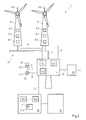
- FIG. 1 shows a schematic view of a first embodiment of a wind energy system 2 according to the present invention.
- the wind energy system 2 comprises a plurality of wind energy devices 4, 6, 8 and a center 10.
- the center 10 is connected via a communication network 12 with the wind energy devices 4, 8.
- the center 10 may include a data processing device.
- a data object generator 10.1 and a control device 10.2 are provided.
- the data object generator 10. 1 is set up to generate a data object X 'by mapping a wind energy device 4, 6, 8.
- the data objects X ' can be stored in a database 10.3 of the center 10.
- the center 10 is further connected to a display device 18, in particular a graphic display device 18.
- sensors 14 may be provided.
- the sensors 14 are connected via a communication network 12 to the center 10.
- the sensors 14 can actively send the acquired operating data to the central unit 10 and / or send it to the central unit 10 as requested by the central unit 10.
- a wind energy device 4, 8 comprises an actuator 16.
- An actuator 16 is in particular a device which generates a mechanical movement in response to an electrical control signal.
- An actuator 16 is connected via the communication network 12 to the center 10. Remote control of an actuator 16 by the center 10 is possible.
- an actuator 16 can be controlled as a function of acquired operating data.
- the generated data objects can be used to control the wind energy system.
- a wind energy device may comprise a plurality of sensors, generators and actuators.
- FIG. 2 shows a schematic view of another embodiment of a wind energy system 2 according to the present invention.
- the wind energy system 2 is an offshore wind energy system 2.
- the offshore wind energy system comprises a plurality of wind energy devices and a center.
- the offshore wind energy system 2 comprises, in particular, a substation 4.
- the substation 4, in particular an offshore substation 4, can have a plurality of subassemblies.
- a transformer 4.1 for transforming the current supplied by the wind turbines 8, a wind turbine control 4.2 and a diesel generator 4.3 are shown here.
- the power cable 6 may have a plurality of power cables 6.
- the power cables 6 are presently formed as a submarine cable 6.
- An energy cable 6 is in particular adapted to transmit the electrical energy generated by a wind turbine 8 to the next wind turbine 8 or to the substation 4.
- a plurality of wind turbines 8 in several strands 20 and 20 strings in series For example, eight strands with six wind turbines each may be provided in a wind energy system.
- One end of a strand 20 is electrically connected to the substation 4 via a power cable.
- the other end may be electrically connectable via an additional power cable to the end of another strand, for example via a switch device.
- one strand can optionally be connected to a plurality of other strands. It is understood that according to other variants of the invention, the wind turbines 8 can also be arranged in ring structures.
- a wind turbine 8 may comprise a plurality of sub-devices 8.1 to 8.5.
- a wind turbine device 8.1 a generator device 8.2, a power distribution device 8.3, an air conditioning device 8.4 and a measuring device 8.5 for acquiring meteorological data, such as a current wind speed, are shown here.
- detection means 22, 24 for detecting current environmental parameters, in particular meteorological parameters may be provided in the offshore wind energy system 2.
- at least one wind measuring mast 22 may be provided with a wind sensor device 22.1 for detecting the wind direction and / or the wind speed. It is understood that a wind measuring mast 22 in addition to at least one wind sensor device 22.1 may have a plurality of further sub-devices.
- a measuring buoy 24 is provided in the present embodiment.
- a sensor device 24.1 for detecting the swell is shown.
- the measuring buoy 24 may have a plurality of sub-devices.
- a plurality of wind measuring masts and / or measuring buoys can be provided.
- the electrical energy generated by the wind turbines 8 can via a further power cable 26 from the substation 4 directly or via a
- High-voltage DC transmission platform to be transferred to an onshore substation 28 and fed from there into the grid.
- the wind energy devices and / or sub-devices can furthermore have a multiplicity of sensors in order to detect the operating states of the individual wind energy devices and / or sub-devices.
- the wind energy devices and / or sub-devices may include a plurality of actuators. The actuators can in particular be controlled automatically, as will be explained in more detail below.
- a central unit 10 is provided in the present case.
- the center 10 may be located remotely from the substation 4 and in particular on land.
- the center 10 may comprise data processing means.
- the center 10 comprises a data object generator 10.1, a control device 10.2 and a database 10.3.
- an interface device 18, in particular a suitable display device 18, is provided in the present case.
- the display device 18 may be configured to visualize various information to a user, such as current states of various wind energy devices. It is understood that further interface devices, such as keyboard, mouse, printer, etc. may be provided.
- a virtual image of the wind energy system in the form of a plurality of data objects can be displayed graphically on the display device 18 and modified by interface devices, for example.
- a data object generator 10.1 is provided.
- the data object generator 10.1 is configured to map a real wind energy device as a data object X '.
- the entire wind energy system 2 can be imaged.
- the corresponding wind energy device can first be analyzed and, for example, subdivided into a plurality of sub-devices.
- the technical specifications (by the manufacturer) of the respective wind energy device can be made available.
- the data object generator 10. 1 is set up to generate data objects X 'as a function of the technical information.
- the technical specification ie the technical properties and functions of the wind energy device, can be mapped as attributes and / or methods in a data object X '.
- control device 10.2 can then control at least the real wind energy device corresponding to the data object X'.
- the individual wind energy devices and / or the sub-devices can exchange data with each other and in particular with the center via the communication network 12.
- wireless or wired communication channels may be provided.
- the sub-devices of the various wind energy devices in turn may have sub-devices.
- the center 10 may be configured to control two or more wind energy systems.
- An exemplary data object X ' is in FIG. 3 displayed.
- data objects are always provided with a "'" in the present case.
- the data object X ' may have a unique address 30.
- RDS-PP Reference Designation System for Power Plants
- a data object X ' may include a plurality of attributes 32 and a plurality of methods 34.
- the attributes 32 may in particular include attribute values. For example, current states of the wind energy device can be detected by sensors in the wind energy device. The operating states can then be written as attribute values in the corresponding data object X '.
- Exemplary and non-terminating operating conditions are the status of a fire protection system (eg, activated or deactivated), the currently generated amount of electricity from a generator of a wind turbine or the currently generated power of the generator, the temperature of a technical component of a wind energy facility, the current wind speed measured by a wind meter, Etc.
- a fire protection system eg, activated or deactivated
- the currently generated amount of electricity from a generator of a wind turbine or the currently generated power of the generator the temperature of a technical component of a wind energy facility
- the current wind speed measured by a wind meter, Etc the current wind speed measured by a wind meter
- attribute values of attributes that correspond, for example, to a real actuator can be modified.
- setpoints for actuators of the wind energy device can be specified.
- the setpoint values can for example be predefined automatically from another data object and made available to the other data object as an input.
- this value can be transmitted, in particular in the form of a control signal, to the corresponding wind energy device be transferred and adjusted accordingly. This is possible in particular by the unique address structure.
- the real wind energy device corresponding to the data object can be controlled.
- methods 34 can also be provided in the data object X '.
- the methods 34 may also be provided for modifying the attributes 32 of the data object X 'or for changing the data object X'. It is understood that further methods 34 and attributes 32 may be provided.
- a data object X ' can also be linked to one or more data objects.
- it can have data inputs and / or data outputs.
- the data object generator is configured to map the actual links of wind energy devices of the wind energy system and to link the data objects accordingly.
- associations of wind energy devices can result, for example, from the energy flow and / or data flow between real wind energy devices.
- the substation 4 is electrically connected via a power cable 6 to a wind turbine 8.
- the Substationsrtzêt 4 'in this case can therefore be linked to the wind turbine data object 8' via a power cable data object 6 '.
- the current flow from the wind turbine 8 can be virtually imaged via a power cable 8 to the sub-device 4.
- FIG. 4 shows by way of example a simplified structure of data objects of a wind energy system according to the present invention.
- at least one substation data object 4' a plurality of energy cable data objects 6 ', a plurality of wind turbine data objects 8', a measurement mast data object 22 ', a measurement bay data object 24' and a high voltage network cable data object 26 'can be provided.
- the individual objects 4 'to 26' can be linked together. For clarity, only some of the links are shown by dashed lines.
- the substate data object 4 ' may be connected to a plurality of network power cable data objects 6', a measurement mast data object 22 ', a mesa data object 24' and a high voltage network cable data object 26 '.
- a network energy cable data object 6 ' may be connected to a plurality of wind turbine data objects 8'.
- the structure of the data objects 4 'to 26' corresponds (essentially) to the real structure of the corresponding wind energy devices 4 to 16 or of the wind energy system 2 (cf. Fig. 2 ).
- a wind energy device may have a plurality of sub-devices.
- Each sub-device may again have a plurality of sub-devices.
- an improved control is achieved if the respective wind energy devices are depicted as detailed as data objects. As a particularly advantageous the arrangement of data objects in a tree structure is shown.
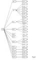
- FIG. 5 shows the wind turbine data object 8 'with a plurality of subdevices 8.1' to 8.12 'in a tree structure.
- a wind turbine data object 8 'corresponding to the real wind turbine 8 may include a wind turbine data object 8.1', a generator device object 8.2 ', a power distribution data object 8.3', an air-conditioning data object 8.4 ', a measurement device data object 8.5', an infrastructure data object 8.6 ', a shared object data object 8.7', a potential equalization data object 8.8 ', a power generation and distribution data object 8.9', a fire protection data object 8.10 ', an on-board crane data object 8.11', and an operational management data object 8.12 'may be provided.
- Subdevices 8.1 'to 8.12' may themselves be subdivided into subdevices 8.1.1 'to 8.12.1'.
- the wind turbine data object 8.1 ' may be a rotor data object 8.1.1', a rotor blade adaptation data object 8.1.2 ', a powertrain data object 8.1.3', a nacelle tracking transmission data object 8.1.4 ', a lubrication system data object 8.1.5', and an electrical control and protection system data object 8.1 .6 'exhibit.
- the generator device data object 8.2 'can have, in addition to a generator data object 8.2.1', a generator cooling data object 8.2.2 'and a transducer data object 8.2.3' have.
- the power distribution data object 8.3 ' may include a generator output data object 8.3.1', a low voltage main distribution data object 8.3.2 'and a transformer data object 8.3.3'.
- the climatic data object 8.4 ' may include a tower climatic data object 8.4.1'.
- the measurement device data object 8.5 ' may include an anemometer data object 8.5.1'.
- the infrastructure data object 8.6 ' may have an access data object 8.6.1'.
- the data object 8.7 'for shared devices may, for example, have a nacelle data object 8.7.1'.
- the potential equalization data object 8.8 ' may comprise a grounding data object 8.8.1', an internal lightning protection data object 8.8.2 'and an external lightning protection data object 8.8.3'.
- the power generation and distribution data object 8.9 ' may include a wind turbine building data object 8.9.1'.
- the fire protection data object 8.10 ' may have a fire alarm data object 8.10.1'.
- the farm management data object 8.12 ' may include a remote monitoring data object 8.12.1'.
- these sub-devices in turn can be subdivided into other sub-facilities. It is understood that the other wind energy devices may be subdivided in a similar manner. By subdividing a wind energy device into a plurality of sub-devices, a sub-device can be controlled in a targeted and user-friendly manner. In particular, an immediate control of the sub-device is possible.
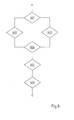
- FIG. 6 shows a flowchart of an embodiment of a method according to the present invention for controlling a wind energy system 2.
- a data object X ' is to be generated by mapping a wind energy device or a sub-device, it can be checked in a first step 601 whether a master data object already exists for the wind energy device type or sub-device type. If this is not the case, a master data object can first be generated in a step 602.
- the device to be imaged can be analyzed and / or technical specifications of the device can be read into the center, including the data object generator.
- properties, structures and / or functions of the device can be determined. For example, it can be analyzed which state data can be detected by sensors in the device and / or which controllable actuators are provided in the device.
- Properties, structures and / or functions of the device can be mapped in a data object by attributes and / or methods.
- a data object may be provided with data inputs and outputs to map the signal and / or energy flow between devices.
- the requirements for the device can be specified and the device must be designed according to the requirements.
- the master data object After the master data object has been generated, it can be integrated into the already depicted wind energy system and stored (step 604). On the other hand, the master data object can be stored as a template for the generation of further data objects of similar facilities.
- a new data object for the wind energy device can be derived from the master data object in step 603.
- the derived data object may then be integrated in step 604 into the already depicted wind energy system.
- the real wind energy system can be controlled (steps 605 and 606).
- the current attribute values of a data object can be displayed and / or modified.
- current state values of a wind energy device can be displayed.
- further attribute values can be modified automatically or manually (step 605). If a modification is detected, in step 606 a control signal may be transmitted to the real device. User-friendly and reliable control of a complex wind energy system can be guaranteed.
Landscapes
- Engineering & Computer Science (AREA)
- General Engineering & Computer Science (AREA)
- Combustion & Propulsion (AREA)
- Life Sciences & Earth Sciences (AREA)
- Sustainable Development (AREA)
- Sustainable Energy (AREA)
- Chemical & Material Sciences (AREA)
- Mechanical Engineering (AREA)
- General Physics & Mathematics (AREA)
- Automation & Control Theory (AREA)
- Physics & Mathematics (AREA)
- Wind Motors (AREA)
- Control Of Eletrric Generators (AREA)
Applications Claiming Priority (1)
| Application Number | Priority Date | Filing Date | Title |
|---|---|---|---|
| DE102012011216A DE102012011216A1 (de) | 2012-06-06 | 2012-06-06 | Steuerung eines windenergiesystems |
Publications (2)
| Publication Number | Publication Date |
|---|---|
| EP2672110A2 true EP2672110A2 (fr) | 2013-12-11 |
| EP2672110A3 EP2672110A3 (fr) | 2017-06-21 |
Family
ID=48190200
Family Applications (1)
| Application Number | Title | Priority Date | Filing Date |
|---|---|---|---|
| EP13165208.3A Withdrawn EP2672110A3 (fr) | 2012-06-06 | 2013-04-24 | Commande d'un système d'énergie éolienne |
Country Status (2)
| Country | Link |
|---|---|
| EP (1) | EP2672110A3 (fr) |
| DE (1) | DE102012011216A1 (fr) |
Cited By (4)
| Publication number | Priority date | Publication date | Assignee | Title |
|---|---|---|---|---|
| EP3394438A4 (fr) * | 2015-12-22 | 2019-05-15 | Envision Energy (Jiangsu) Co., Ltd. | Procédé et système de commande d'éoliennes dans un parc éolien |
| CN110632880A (zh) * | 2019-10-10 | 2019-12-31 | 上海电机学院 | 基于5g云网络传输的风电场主控系统 |
| CN113038407A (zh) * | 2021-03-18 | 2021-06-25 | 西安热工研究院有限公司 | 一种海上风电场监控报警系统 |
| CN114294188A (zh) * | 2021-12-25 | 2022-04-08 | 华能湖南桂东风电有限责任公司 | 一种基于5g的风机运维系统、方法和电子设备 |
Families Citing this family (1)
| Publication number | Priority date | Publication date | Assignee | Title |
|---|---|---|---|---|
| DE102014113292B4 (de) | 2014-09-16 | 2020-06-18 | Christoph Lucks | Messboje |
Citations (3)
| Publication number | Priority date | Publication date | Assignee | Title |
|---|---|---|---|---|
| WO2001077525A1 (fr) | 2000-04-07 | 2001-10-18 | Windlynx Systems, B.V. | Systeme de commande de parc d'eoliennes (scada) |
| DE102007039428A1 (de) * | 2007-08-21 | 2009-02-26 | Beckhoff Automation Gmbh | Programmiervorrichtung für ein Netzwerk aus Steuerknoten und Anlage mit einer solchen Programmiervorrichtung |
| US20120004781A1 (en) * | 2010-06-30 | 2012-01-05 | Vestas Wind Systems A/S | System, method, and computer program product for utilizing a wind park as a variable power system stabilizer |
Family Cites Families (3)
| Publication number | Priority date | Publication date | Assignee | Title |
|---|---|---|---|---|
| SG109956A1 (en) * | 2001-06-19 | 2005-04-28 | Eutech Cybernetics Pte Ltd | Method and apparatus for automatically generating a scada system |
| US7698024B2 (en) * | 2007-11-19 | 2010-04-13 | Integrated Power Technology Corporation | Supervisory control and data acquisition system for energy extracting vessel navigation |
| US8433425B2 (en) * | 2011-04-29 | 2013-04-30 | General Electric Company | Method, system and computer program product for dynamic rule engine for a wind turbine farm |
-
2012
- 2012-06-06 DE DE102012011216A patent/DE102012011216A1/de not_active Ceased
-
2013
- 2013-04-24 EP EP13165208.3A patent/EP2672110A3/fr not_active Withdrawn
Patent Citations (3)
| Publication number | Priority date | Publication date | Assignee | Title |
|---|---|---|---|---|
| WO2001077525A1 (fr) | 2000-04-07 | 2001-10-18 | Windlynx Systems, B.V. | Systeme de commande de parc d'eoliennes (scada) |
| DE102007039428A1 (de) * | 2007-08-21 | 2009-02-26 | Beckhoff Automation Gmbh | Programmiervorrichtung für ein Netzwerk aus Steuerknoten und Anlage mit einer solchen Programmiervorrichtung |
| US20120004781A1 (en) * | 2010-06-30 | 2012-01-05 | Vestas Wind Systems A/S | System, method, and computer program product for utilizing a wind park as a variable power system stabilizer |
Non-Patent Citations (1)
| Title |
|---|
| ALLEN K. C. LEE ET AL: "Inheritance and polymorphism in real-time monitoring and control systems", JOURNAL OF INTELLIGENT MANUFACTURING, vol. 11, no. 3, 1 January 2000 (2000-01-01), GB, pages 285 - 294, XP055536040, ISSN: 0956-5515, DOI: 10.1023/A:1008927520325 * |
Cited By (4)
| Publication number | Priority date | Publication date | Assignee | Title |
|---|---|---|---|---|
| EP3394438A4 (fr) * | 2015-12-22 | 2019-05-15 | Envision Energy (Jiangsu) Co., Ltd. | Procédé et système de commande d'éoliennes dans un parc éolien |
| CN110632880A (zh) * | 2019-10-10 | 2019-12-31 | 上海电机学院 | 基于5g云网络传输的风电场主控系统 |
| CN113038407A (zh) * | 2021-03-18 | 2021-06-25 | 西安热工研究院有限公司 | 一种海上风电场监控报警系统 |
| CN114294188A (zh) * | 2021-12-25 | 2022-04-08 | 华能湖南桂东风电有限责任公司 | 一种基于5g的风机运维系统、方法和电子设备 |
Also Published As
| Publication number | Publication date |
|---|---|
| DE102012011216A1 (de) | 2013-12-12 |
| EP2672110A3 (fr) | 2017-06-21 |
Similar Documents
| Publication | Publication Date | Title |
|---|---|---|
| EP2667023B1 (fr) | Commande d'un système d'énergie éolienne | |
| EP2020506B2 (fr) | Procédé de détermination d'une réserve de réglage ainsi qu'éolienne dotée d'une unité de commande destinée à déterminer la réserve de réglage | |
| EP3070556B1 (fr) | Procédé, dispositif de calcul, unité d'utilisateur et système de paramétrage d'un appareil électrique | |
| EP2828522B1 (fr) | Procédé permettant de configurer une éolienne et éolienne | |
| EP2598954B1 (fr) | Configuration des liaisons de communication des appareils de terrain d'un équipement d'automatisation de la distribution d'énergie | |
| EP2672110A2 (fr) | Commande d'un système d'énergie éolienne | |
| EP1659287A2 (fr) | Dispositif et procédure de test de performance d'une installation d'énergie éolienne | |
| EP3380722B1 (fr) | Procédé d'émission d'instructions de commande ou de notifications d'événement pour une éolienne ou un parc éolien ainsi que dispositif d'évaluation et système associés | |
| EP2553263A2 (fr) | Dispositif de commande pour éolienne | |
| WO2012055566A2 (fr) | Procédé de détection de données à cycle court pour la surveillance de l'énergie et pour la commande de réseau dans le système de compteur intelligent/réseau électrique intelligent à l'aide d'un logiciel médiateur intelligent distribué | |
| EP2988183A1 (fr) | Système de télécommande, système et procédé d'observation et/ou de commande d'une installation | |
| DE102014107115A1 (de) | Vorrichtung und Verfahren zur Regelung von dezentralen Energieerzeugungsanlagen | |
| DE102015114174A1 (de) | Übertragung von Daten von Windenergieanlagen und Windparks an eine Leitzentrale | |
| DE102016122862A1 (de) | Messsystem und ein Messverfahren zum Vermessen eines Stators einer getriebelosen Windenergieanlage | |
| DE10300174B3 (de) | Windenergieanlage mit mindestens zwei Komponenten und einem Datennetz | |
| WO2011157348A1 (fr) | Procédé et système de surveillance d'état pour éoliennes | |
| DE102021210569B4 (de) | Verfahren zum Betreiben einer Windenergieanlage in einem Windpark und Windparkmanager | |
| WO2020094393A1 (fr) | Prédiction de valeur de paramètre énergétique d'un parc éolien | |
| WO2021122347A1 (fr) | Procédé de détermination d'une durée de vie restante d'une turbine éolienne et turbine éolienne | |
| EP3244279A1 (fr) | Procédé de fonctionnement d'un indicateur d'erreurs | |
| EP3507660B1 (fr) | Procédé de transmission de grandeur de réglage d'un régulateur, en particulier d'un régulateur de parc éolien, à des unités ainsi qu'unité à réguler et régulateur | |
| EP2908399A2 (fr) | Procédé de surveillance d'états d'un réseau basse tension | |
| EP3931443B1 (fr) | Kit de capteur pour une éolienne | |
| EP3864482A1 (fr) | Acquisition de données configurable à distance d'aérogénérateurs | |
| AT510392B1 (de) | Verfahren zur überwachung einer daten-übertragungsstrecke in grossanlagen und vorrichtung zur durchführung des verfahrens |
Legal Events
| Date | Code | Title | Description |
|---|---|---|---|
| PUAI | Public reference made under article 153(3) epc to a published international application that has entered the european phase |
Free format text: ORIGINAL CODE: 0009012 |
|
| AK | Designated contracting states |
Kind code of ref document: A2 Designated state(s): AL AT BE BG CH CY CZ DE DK EE ES FI FR GB GR HR HU IE IS IT LI LT LU LV MC MK MT NL NO PL PT RO RS SE SI SK SM TR |
|
| AX | Request for extension of the european patent |
Extension state: BA ME |
|
| PUAL | Search report despatched |
Free format text: ORIGINAL CODE: 0009013 |
|
| AK | Designated contracting states |
Kind code of ref document: A3 Designated state(s): AL AT BE BG CH CY CZ DE DK EE ES FI FR GB GR HR HU IE IS IT LI LT LU LV MC MK MT NL NO PL PT RO RS SE SI SK SM TR |
|
| AX | Request for extension of the european patent |
Extension state: BA ME |
|
| RIC1 | Information provided on ipc code assigned before grant |
Ipc: F03D 7/00 20060101AFI20170518BHEP Ipc: G05B 15/02 20060101ALI20170518BHEP |
|
| STAA | Information on the status of an ep patent application or granted ep patent |
Free format text: STATUS: REQUEST FOR EXAMINATION WAS MADE |
|
| 17P | Request for examination filed |
Effective date: 20171214 |
|
| RBV | Designated contracting states (corrected) |
Designated state(s): AL AT BE BG CH CY CZ DE DK EE ES FI FR GB GR HR HU IE IS IT LI LT LU LV MC MK MT NL NO PL PT RO RS SE SI SK SM TR |
|
| STAA | Information on the status of an ep patent application or granted ep patent |
Free format text: STATUS: EXAMINATION IS IN PROGRESS |
|
| 17Q | First examination report despatched |
Effective date: 20190102 |
|
| RAP1 | Party data changed (applicant data changed or rights of an application transferred) |
Owner name: RWE RENEWABLES GMBH |
|
| GRAP | Despatch of communication of intention to grant a patent |
Free format text: ORIGINAL CODE: EPIDOSNIGR1 |
|
| STAA | Information on the status of an ep patent application or granted ep patent |
Free format text: STATUS: GRANT OF PATENT IS INTENDED |
|
| RIC1 | Information provided on ipc code assigned before grant |
Ipc: F03D 7/04 20060101AFI20210416BHEP Ipc: G05B 15/02 20060101ALI20210416BHEP |
|
| INTG | Intention to grant announced |
Effective date: 20210506 |
|
| STAA | Information on the status of an ep patent application or granted ep patent |
Free format text: STATUS: THE APPLICATION IS DEEMED TO BE WITHDRAWN |
|
| 18D | Application deemed to be withdrawn |
Effective date: 20210917 |