EP2672112A1 - Verfahren zur Schmierung eines Getriebes für eine Windturbine - Google Patents
Verfahren zur Schmierung eines Getriebes für eine Windturbine Download PDFInfo
- Publication number
- EP2672112A1 EP2672112A1 EP12170773.1A EP12170773A EP2672112A1 EP 2672112 A1 EP2672112 A1 EP 2672112A1 EP 12170773 A EP12170773 A EP 12170773A EP 2672112 A1 EP2672112 A1 EP 2672112A1
- Authority
- EP
- European Patent Office
- Prior art keywords
- lubricant
- gearbox
- bearings
- pump
- gears
- Prior art date
- Legal status (The legal status is an assumption and is not a legal conclusion. Google has not performed a legal analysis and makes no representation as to the accuracy of the status listed.)
- Withdrawn
Links
- 238000000034 method Methods 0.000 title claims abstract description 24
- 230000001050 lubricating effect Effects 0.000 title claims abstract description 10
- 239000000314 lubricant Substances 0.000 claims abstract description 77
- 238000005461 lubrication Methods 0.000 claims abstract description 18
- 239000004605 External Lubricant Substances 0.000 description 1
- 230000005611 electricity Effects 0.000 description 1
Images


Classifications
-
- F—MECHANICAL ENGINEERING; LIGHTING; HEATING; WEAPONS; BLASTING
- F03—MACHINES OR ENGINES FOR LIQUIDS; WIND, SPRING, OR WEIGHT MOTORS; PRODUCING MECHANICAL POWER OR A REACTIVE PROPULSIVE THRUST, NOT OTHERWISE PROVIDED FOR
- F03D—WIND MOTORS
- F03D80/00—Details, components or accessories not provided for in groups F03D1/00 - F03D17/00
- F03D80/70—Bearing or lubricating arrangements
-
- F—MECHANICAL ENGINEERING; LIGHTING; HEATING; WEAPONS; BLASTING
- F04—POSITIVE - DISPLACEMENT MACHINES FOR LIQUIDS; PUMPS FOR LIQUIDS OR ELASTIC FLUIDS
- F04B—POSITIVE-DISPLACEMENT MACHINES FOR LIQUIDS; PUMPS
- F04B23/00—Pumping installations or systems
- F04B23/04—Combinations of two or more pumps
- F04B23/08—Combinations of two or more pumps the pumps being of different types
-
- F—MECHANICAL ENGINEERING; LIGHTING; HEATING; WEAPONS; BLASTING
- F05—INDEXING SCHEMES RELATING TO ENGINES OR PUMPS IN VARIOUS SUBCLASSES OF CLASSES F01-F04
- F05B—INDEXING SCHEME RELATING TO WIND, SPRING, WEIGHT, INERTIA OR LIKE MOTORS, TO MACHINES OR ENGINES FOR LIQUIDS COVERED BY SUBCLASSES F03B, F03D AND F03G
- F05B2260/00—Function
- F05B2260/98—Lubrication
-
- F—MECHANICAL ENGINEERING; LIGHTING; HEATING; WEAPONS; BLASTING
- F05—INDEXING SCHEMES RELATING TO ENGINES OR PUMPS IN VARIOUS SUBCLASSES OF CLASSES F01-F04
- F05B—INDEXING SCHEME RELATING TO WIND, SPRING, WEIGHT, INERTIA OR LIKE MOTORS, TO MACHINES OR ENGINES FOR LIQUIDS COVERED BY SUBCLASSES F03B, F03D AND F03G
- F05B2270/00—Control
- F05B2270/10—Purpose of the control system
- F05B2270/107—Purpose of the control system to cope with emergencies
- F05B2270/1071—Purpose of the control system to cope with emergencies in particular sudden load loss
-
- Y—GENERAL TAGGING OF NEW TECHNOLOGICAL DEVELOPMENTS; GENERAL TAGGING OF CROSS-SECTIONAL TECHNOLOGIES SPANNING OVER SEVERAL SECTIONS OF THE IPC; TECHNICAL SUBJECTS COVERED BY FORMER USPC CROSS-REFERENCE ART COLLECTIONS [XRACs] AND DIGESTS
- Y02—TECHNOLOGIES OR APPLICATIONS FOR MITIGATION OR ADAPTATION AGAINST CLIMATE CHANGE
- Y02E—REDUCTION OF GREENHOUSE GAS [GHG] EMISSIONS, RELATED TO ENERGY GENERATION, TRANSMISSION OR DISTRIBUTION
- Y02E10/00—Energy generation through renewable energy sources
- Y02E10/70—Wind energy
- Y02E10/72—Wind turbines with rotation axis in wind direction
Definitions
- the present invention relates to a method for lubricating a gearbox for a wind turbine. More particular, the present invention relates to a method for lubricating a gearbox for a wind turbine in emergency situations such as for example grid loss or failure of the electrical pump.
- Lubrication of rotating parts such as gears and bearings in gearboxes for wind turbines during operation of the wind turbine is very important. No or not sufficient provision of lubricant to these parts can lead to damages and to failure of such parts.
- bearings supporting gears and shafts in the gearbox, and more particularly plain bearings are very sensitive to good lubrication and need at all times sufficiently be provided with lubricant in order not to fail.
- lubricant is continuously fed to the rotating parts by means of an electrical pump and usually this is sufficient for feeding the right amount of lubricant to the rotating parts.
- the lubricant feeding may not be sufficient anymore for the rotating parts in the gearbox, and especially the bearings, to continue working properly.
- the present invention provides a method for lubricating a gearbox of a wind turbine.
- the gearbox comprises a plurality of gears and shafts supported by bearings of which at least one is a plain bearing.
- the gearbox furthermore comprises a lubrication system with a mechanical pump and an electrical pump for feeding the gears and bearings with lubricant.
- a difference between volume capacity of the mechanical and electrical pump is maximum 40%.
- the method comprises controlling at least one valve for:
- An advantage of a method according to embodiments of the invention is that whenever the electrical pump fails to work properly, e.g. by loss grid or simply by a failure of the electrical pump, sufficient lubricant is provided to the bearings, and more particularly to the at least one plain bearing, for preventing them from being damaged because of a too low amount of lubricant.
- the method may furthermore comprise, during start-up of the gearbox, feeding lubricant to the gears by means of the mechanical pump.
- the lubrication system may comprise a plurality of valves and the method may comprise controlling a plurality of valves.
- controlling the at least one valve may be electrically driven.
- controlling the at least one valve may be pressure-driven.
- controlling the at least one valve may be electrical fail safe driven.
- controlling the valves may partly be pressure-driven and partly be electrically driven.
- the present invention provides a method for lubricating a gearbox of a wind turbine.
- the gearbox comprises a plurality of gears and shafts supported by bearings of which at least one is a plain bearing, and a lubrication system with a mechanical pump and an electrical pump for feeding the gears and bearings with lubricant wherein a difference between volume capacity of the mechanical pump and the electrical pump is maximum 40%.
- the method comprises controlling at least one valves for:
- An advantage of a method according to embodiments of the invention is that whenever there is a problem with the electrical pump, e.g. when there is a grid loss or when the electrical pump fails, the bearings in the gearbox are still provided with enough lubricant so as to provide them from being damaged.
- Fig. 1 and Fig. 2 illustrate a lubrication system 1 for a gearbox 10 according to embodiments of the present invention.
- the lubrication system 1 comprises a lubricant reservoir 2, a mechanical pump 3 and an electrical pump 4.
- a difference between volume capacity of the mechanical pump 3 and the electrical pump 4 is maximum 40%. This means that when the sum of the volume capacities of the mechanical pump 3 and the electrical pump 4 is, for example, 100L, then the volume capacity of the mechanical pump 3 may minimum be 30L and maximum 70L and the volume capacity of the electrical pump 4 may then respectively be maximum 70L and minimum 30L.
- the volume capacity of the mechanical pump 3 and the electrical pump 4 may be equal and may, for example, be 50L.
- the lubricant reservoir 2 comprises lubricant for lubricating gears G and bearings B in the gearbox 10.
- at least one of the bearings B in the gearbox 10 may be a plain bearing.
- more than one of the bearings B in the gearbox 10 may be plain bearings and according to still further embodiments of the invention, all bearings B in the gearbox 10 may be plain bearings.
- the lubrication system 1 may be located inside the gearbox 10. According to other embodiments, however, and as illustrated in Fig. 2 , the lubrication system 1 may also be located outside the gearbox 10, or in other words may be an external lubricant reservoir 2.
- the lubrication system 1 furthermore comprises one valve 5 for controlling the flow of the lubricant and a control system (not shown) for controlling this valve 5.
- controlling the valve 5 may be pressure-driven. In that case, because only the electrical pump is providing lubricant, the pressure is not high enough to open the valve 5 and thus lubricant only flows to the bearings B. According to other embodiments of the invention, controlling the valve 5 may be electrically driven.
- controlling the valve 5 may be electrical fail safe driven. This means that, whenever there is no electricity, the valve 5 will take the right position so as only to allow flow of lubricant to the bearings B and not to the gears G.
- controlling the valve 5 may be pressure-driven, electrically driven or electrical fail safe driven.
- the control system drives the valve 5 to close such as to allow flow of lubricant from the lubricant reservoir 2 through the mechanical pump 3 to the bearings B and not to the gears G (indicated by the bolt line in Fig. 5 ).
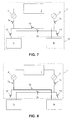
- Fig. 6 and Fig. 7 illustrate another embodiment of the present invention.
- the lubrication system 1 is similar to the one described in the previous embodiment but now comprises a plurality of valves 5a to 5f instead of only one valve 5 for controlling the flow of the lubricant. Similar as for the above embodiment, the lubrication system 1 may be located inside the gearbox 10 (see Fig. 6 ) or may be located outside the gearbox 10 (see Fig. 7 ).
- the electrical pump 4 provides lubricant to the bearings B (see Fig. 8 ).
- the control system controls the valves 5a to 5f such that valves 5a and 5b open to allow lubricant to flow from the lubricant reservoir 2 towards the bearings B through the electrical pump 4 (lubricant flow is indicated by the bolt line in Fig. 8 ).
- lubricant may furthermore be provided to the gears G by means of the mechanical pump 3. This is illustrated in Fig. 9 .
- the control system controls the valves 5a to 5f such that valves 5a to 5c and 5e are open so as to allow lubricant flow to the bearings B and the gears G and that valves 5d and 5f are closed.
- valves 5a to 5f controls the valves 5a to 5f such that these valves 5a to 5f are all opened such that lubricant can flow from the lubricant reservoir 2 through the mechanical pump 3 and the electrical pump 4 to the gears G and the bearings B.
- Fig. 10 the flow of lubricant is indicated by bolt line.
- the control system drives the valves 5a to 5f such that valves 5c and 5d are opened to allow flow of lubricant from the lubricant reservoir 2 through the mechanical pump 3 to the bearings B and that the other valves 5a, 5b, 5e and 5f stay closed (see Fig. 11 ).
- controlling the valves 5a to 5f may be electrically driven, electrical fail safe driven or electrically and pressure-driven.
- valves 5a to 5f being electrically and pressure-driven will be described in more detail.
- the electrical pump 4 is working and allows lubricant to flow towards valve 5a.
- the valve 5a will open and further allow flow of the lubricant.
- the lubricant pressure valve 5b will close and allow lubricant to flow to the bearings B.
- Valve 5f is thereby electrically controlled such that it stays closed and substantially no lubricant flows to the gears G at that time.
- valves 5a and 5c During normal operation of the gearbox 10 both the mechanical pump 3 and the electrical pump 4 work and allow lubricant to flow from the lubricant reservoir 2 through respectively valves 5a and 5c. Because of the pressure exerted by the lubricant, these valves 5a and 5c will open and allow further flow of the lubricant. Similarly, because of the lubricant flow, respectively valves 5b and 5f and valves 5d and 5e will open and allow lubricant to be provided to respectively the gears G and the bearings B. Summarized, during normal operation the lubricant pressure will be high enough to make all the valves 5a to 5f open such that the lubricant can flow towards the gears G and the bearings B.
- valve 5c When the electrical pump 4 stops working, only the mechanical pump 3 will be left to provide lubricant to components of the gearbox 10. In that case, lubricant pressure will cause valve 5c to stay open and to allow further flow of lubricant. Similarly, valve 5d will also stay open to allow lubricant to be provided to the bearings B. Valve 5e will then electrically be controlled so as to close to not further allow lubricant flow to the gears G. Valves 5a, 5b and 5f will close because of a too low pressure of the lubricant.
Landscapes
- Engineering & Computer Science (AREA)
- Mechanical Engineering (AREA)
- General Engineering & Computer Science (AREA)
- Life Sciences & Earth Sciences (AREA)
- Sustainable Development (AREA)
- Sustainable Energy (AREA)
- Chemical & Material Sciences (AREA)
- Combustion & Propulsion (AREA)
- General Details Of Gearings (AREA)
- Wind Motors (AREA)
Priority Applications (7)
| Application Number | Priority Date | Filing Date | Title |
|---|---|---|---|
| EP12170773.1A EP2672112A1 (de) | 2012-06-05 | 2012-06-05 | Verfahren zur Schmierung eines Getriebes für eine Windturbine |
| ES13720914T ES2701788T3 (es) | 2012-06-05 | 2013-05-02 | Método para lubricar una caja de engranajes de una turbina eólica |
| PCT/EP2013/059098 WO2013182355A1 (en) | 2012-06-05 | 2013-05-02 | Method for lubricating a gearbox for a wind turbine |
| JP2015515439A JP6185572B2 (ja) | 2012-06-05 | 2013-05-02 | 風力タービン用ギアボックスの潤滑方法 |
| US14/402,716 US9458833B2 (en) | 2012-06-05 | 2013-05-02 | Method for lubricating a gearbox for a wind turbine |
| EP13720914.4A EP2855928B1 (de) | 2012-06-05 | 2013-05-02 | Method for lubricating a gearbox for a wind turbine |
| CN201380023718.6A CN104364519B (zh) | 2012-06-05 | 2013-05-02 | 用于润滑风力涡轮机齿轮箱的方法 |
Applications Claiming Priority (1)
| Application Number | Priority Date | Filing Date | Title |
|---|---|---|---|
| EP12170773.1A EP2672112A1 (de) | 2012-06-05 | 2012-06-05 | Verfahren zur Schmierung eines Getriebes für eine Windturbine |
Publications (1)
| Publication Number | Publication Date |
|---|---|
| EP2672112A1 true EP2672112A1 (de) | 2013-12-11 |
Family
ID=48325687
Family Applications (2)
| Application Number | Title | Priority Date | Filing Date |
|---|---|---|---|
| EP12170773.1A Withdrawn EP2672112A1 (de) | 2012-06-05 | 2012-06-05 | Verfahren zur Schmierung eines Getriebes für eine Windturbine |
| EP13720914.4A Active EP2855928B1 (de) | 2012-06-05 | 2013-05-02 | Method for lubricating a gearbox for a wind turbine |
Family Applications After (1)
| Application Number | Title | Priority Date | Filing Date |
|---|---|---|---|
| EP13720914.4A Active EP2855928B1 (de) | 2012-06-05 | 2013-05-02 | Method for lubricating a gearbox for a wind turbine |
Country Status (6)
| Country | Link |
|---|---|
| US (1) | US9458833B2 (de) |
| EP (2) | EP2672112A1 (de) |
| JP (1) | JP6185572B2 (de) |
| CN (1) | CN104364519B (de) |
| ES (1) | ES2701788T3 (de) |
| WO (1) | WO2013182355A1 (de) |
Cited By (2)
| Publication number | Priority date | Publication date | Assignee | Title |
|---|---|---|---|---|
| US20160076515A1 (en) * | 2013-04-29 | 2016-03-17 | Vestas Wind Systems A/S | Method for starting a wind turbine in a cold climate environment |
| US10982657B2 (en) | 2016-12-22 | 2021-04-20 | Vestas Wind Systems A/S | Temperature control based on weather forecasting |
Families Citing this family (2)
| Publication number | Priority date | Publication date | Assignee | Title |
|---|---|---|---|---|
| CN108953077B (zh) * | 2018-07-26 | 2021-01-22 | 北京金风科创风电设备有限公司 | 润滑系统、润滑方法及风力发电机组 |
| US11603778B2 (en) * | 2018-09-04 | 2023-03-14 | Volvo Truck Corporation | Engine system and method for a vehicle |
Citations (4)
| Publication number | Priority date | Publication date | Assignee | Title |
|---|---|---|---|---|
| WO2005088131A1 (en) * | 2004-03-12 | 2005-09-22 | Neg Micon A/S | Variable capacity oil pump |
| DE102008013728A1 (de) * | 2008-03-11 | 2009-09-17 | Kenersys Gmbh | Windenergieanlage zur Erzeugung elektrischer Energie |
| EP2159472A1 (de) * | 2008-08-27 | 2010-03-03 | General Electric Company | Fluidisches System, Antriebsstrang für ein Windrad und Verfahren zur Betätigung eines mechanischen Bauteils |
| US20110204633A1 (en) * | 2010-02-19 | 2011-08-25 | Mitsubishi Heavy Industries, Ltd. | Starting method for rotating machine and starting method for wind turbine generator |
Family Cites Families (15)
| Publication number | Priority date | Publication date | Assignee | Title |
|---|---|---|---|---|
| US4531485A (en) * | 1984-03-01 | 1985-07-30 | Murther Howard D | Over ride oil pump |
| US5199528A (en) * | 1991-12-05 | 1993-04-06 | Atlas Copco Aktiebolag | Flow controller |
| SE509078C2 (sv) * | 1993-10-13 | 1998-11-30 | Kvaerner Hymac Inc | Avbrottssäkrat smörjningssystem för en maskin |
| JP4446622B2 (ja) * | 2001-03-27 | 2010-04-07 | トヨタ紡織株式会社 | 内燃機関用オイルポンプ及びその使用方法 |
| GB2388634A (en) * | 2002-05-15 | 2003-11-19 | Dana Automotive Ltd | Engine lubrication system having dual/auxiliary pump operation |
| JP2005083207A (ja) * | 2003-09-04 | 2005-03-31 | Kanzaki Kokyukoki Mfg Co Ltd | ダリウス式風力発電装置 |
| JP4205026B2 (ja) * | 2004-09-01 | 2009-01-07 | 本田技研工業株式会社 | トランスミッションの油圧供給装置 |
| US7695250B2 (en) * | 2005-11-02 | 2010-04-13 | Gm Global Technology Operations, Inc. | Dual pump assembly |
| CN101196176B (zh) * | 2007-12-26 | 2010-09-29 | 二重集团(德阳)重型装备股份有限公司 | 低温型风力发电机增速机油润滑系统 |
| CN101981313B (zh) * | 2008-07-04 | 2013-07-10 | 三菱重工业株式会社 | 风力发电装置 |
| JP5019135B2 (ja) * | 2009-03-30 | 2012-09-05 | アイシン・エィ・ダブリュ株式会社 | 車両用駆動装置 |
| ES2442176T3 (es) * | 2009-10-23 | 2014-02-10 | Vestas Wind Systems A/S | Sistema de lubricación para un sistema de engranaje de una turbina eólica que proporciona lubricación de emergencia |
| US9151327B2 (en) * | 2010-06-11 | 2015-10-06 | Siemens Aktiengesellschaft | Backup lubrication system for a rotor bearing |
| US8734105B2 (en) * | 2010-09-16 | 2014-05-27 | Vestas Wind Systems A/S | Control system for a wind turbine and method of operating a wind turbine based on monitoring a bearing |
| US20130288843A1 (en) * | 2010-10-15 | 2013-10-31 | Vestas Wind Systems A/S | Machine system having a lubrication system |
-
2012
- 2012-06-05 EP EP12170773.1A patent/EP2672112A1/de not_active Withdrawn
-
2013
- 2013-05-02 WO PCT/EP2013/059098 patent/WO2013182355A1/en not_active Ceased
- 2013-05-02 ES ES13720914T patent/ES2701788T3/es active Active
- 2013-05-02 US US14/402,716 patent/US9458833B2/en active Active
- 2013-05-02 CN CN201380023718.6A patent/CN104364519B/zh active Active
- 2013-05-02 EP EP13720914.4A patent/EP2855928B1/de active Active
- 2013-05-02 JP JP2015515439A patent/JP6185572B2/ja not_active Expired - Fee Related
Patent Citations (4)
| Publication number | Priority date | Publication date | Assignee | Title |
|---|---|---|---|---|
| WO2005088131A1 (en) * | 2004-03-12 | 2005-09-22 | Neg Micon A/S | Variable capacity oil pump |
| DE102008013728A1 (de) * | 2008-03-11 | 2009-09-17 | Kenersys Gmbh | Windenergieanlage zur Erzeugung elektrischer Energie |
| EP2159472A1 (de) * | 2008-08-27 | 2010-03-03 | General Electric Company | Fluidisches System, Antriebsstrang für ein Windrad und Verfahren zur Betätigung eines mechanischen Bauteils |
| US20110204633A1 (en) * | 2010-02-19 | 2011-08-25 | Mitsubishi Heavy Industries, Ltd. | Starting method for rotating machine and starting method for wind turbine generator |
Cited By (3)
| Publication number | Priority date | Publication date | Assignee | Title |
|---|---|---|---|---|
| US20160076515A1 (en) * | 2013-04-29 | 2016-03-17 | Vestas Wind Systems A/S | Method for starting a wind turbine in a cold climate environment |
| US10151299B2 (en) * | 2013-04-29 | 2018-12-11 | Vestas Wind Systems A/S | Method for starting a wind turbine in a cold climate environment |
| US10982657B2 (en) | 2016-12-22 | 2021-04-20 | Vestas Wind Systems A/S | Temperature control based on weather forecasting |
Also Published As
| Publication number | Publication date |
|---|---|
| EP2855928A1 (de) | 2015-04-08 |
| JP2015521267A (ja) | 2015-07-27 |
| CN104364519A (zh) | 2015-02-18 |
| EP2855928B1 (de) | 2018-10-31 |
| ES2701788T3 (es) | 2019-02-25 |
| CN104364519B (zh) | 2017-05-10 |
| JP6185572B2 (ja) | 2017-08-23 |
| US20150139820A1 (en) | 2015-05-21 |
| US9458833B2 (en) | 2016-10-04 |
| WO2013182355A1 (en) | 2013-12-12 |
Similar Documents
| Publication | Publication Date | Title |
|---|---|---|
| EP2351950B1 (de) | Schmierung eines Flüssigkeitsturbinengetriebes im Leerlauf oder bei Netzstromausfall | |
| EP3040553A1 (de) | Windenergieerzeugungsstation und getriebe | |
| EP2855928B1 (de) | Method for lubricating a gearbox for a wind turbine | |
| EP4273374A2 (de) | Schmierung eines achslagers bei einer drehung im und gegen den linken drehrichtung | |
| EP3810977B1 (de) | Fluidsystem für eine windturbine | |
| US11619210B2 (en) | Gearbox system for a wind turbine, wind turbine with a gearbox system, and method for operating a gearbox system | |
| CN102918285A (zh) | 转子轴轴承润滑系统 | |
| EP2479429A2 (de) | Windturbine und Verfahren zum Antreiben eines oder mehrerer hydraulischer Einstellwinkelaktuatoren | |
| CN110520634A (zh) | 用于调节液力机器的设备 | |
| EP2481917A1 (de) | Windkraftanlage mit einem hydrostatischen Getriebe und einer LVRT-Steuerung | |
| CN102748577B (zh) | 一种风力发电机组的润滑方法和润滑系统 | |
| US8400032B2 (en) | Inertia wheel with progressive run up | |
| CN109340544A (zh) | 大型卧式滑动轴承的压力油箱供油系统 | |
| US20130011263A1 (en) | System and method for lubricant flow control | |
| CN102518487B (zh) | 一种汽轮机转子顶轴系统以及应急供油方法 | |
| CN104989468A (zh) | 一种具有离心式油泵的汽轮机供油系统 | |
| JP2016098845A (ja) | 軸受給油装置および軸受給油方法 | |
| NO20141416A1 (no) | Fremgangsmåte og system for regulering av fluid | |
| CN205478909U (zh) | 一种用于磨机动静压轴承的补油系统 | |
| JP6388312B2 (ja) | 滑り軸受給油装置および滑り軸受給油方法 | |
| WO2014168488A1 (en) | Subsea turbomachine assembly with magnetic lift and magnetic coupling | |
| EP2891795B1 (de) | Hydraulikgetriebe, Windturbinengenerator und Betriebssverfahren dafür | |
| CN209278814U (zh) | 大型卧式滑动轴承的压力油箱供油系统 | |
| CN204851344U (zh) | 一种具有离心式油泵的汽轮机供油系统 | |
| JP2012193642A (ja) | 風力発電装置 |
Legal Events
| Date | Code | Title | Description |
|---|---|---|---|
| PUAI | Public reference made under article 153(3) epc to a published international application that has entered the european phase |
Free format text: ORIGINAL CODE: 0009012 |
|
| AK | Designated contracting states |
Kind code of ref document: A1 Designated state(s): AL AT BE BG CH CY CZ DE DK EE ES FI FR GB GR HR HU IE IS IT LI LT LU LV MC MK MT NL NO PL PT RO RS SE SI SK SM TR |
|
| AX | Request for extension of the european patent |
Extension state: BA ME |
|
| 17P | Request for examination filed |
Effective date: 20140521 |
|
| RAP1 | Party data changed (applicant data changed or rights of an application transferred) |
Owner name: ZF WIND POWER ANTWERPEN NV |
|
| STAA | Information on the status of an ep patent application or granted ep patent |
Free format text: STATUS: THE APPLICATION IS DEEMED TO BE WITHDRAWN |
|
| 18D | Application deemed to be withdrawn |
Effective date: 20170103 |