EP2672216A2 - Echangeur de chaleur et raccord de mesure pour échangeur de chaleur - Google Patents
Echangeur de chaleur et raccord de mesure pour échangeur de chaleur Download PDFInfo
- Publication number
- EP2672216A2 EP2672216A2 EP13170786.1A EP13170786A EP2672216A2 EP 2672216 A2 EP2672216 A2 EP 2672216A2 EP 13170786 A EP13170786 A EP 13170786A EP 2672216 A2 EP2672216 A2 EP 2672216A2
- Authority
- EP
- European Patent Office
- Prior art keywords
- heat exchanger
- measuring
- measuring chamber
- connection device
- exchanger according
- Prior art date
- Legal status (The legal status is an assumption and is not a legal conclusion. Google has not performed a legal analysis and makes no representation as to the accuracy of the status listed.)
- Granted
Links
- 239000012530 fluid Substances 0.000 claims abstract description 42
- 230000001419 dependent effect Effects 0.000 claims abstract description 10
- 238000012546 transfer Methods 0.000 claims description 16
- 238000004891 communication Methods 0.000 claims description 3
- 238000007599 discharging Methods 0.000 abstract description 2
- 238000013461 design Methods 0.000 description 7
- 238000004519 manufacturing process Methods 0.000 description 5
- 238000011161 development Methods 0.000 description 3
- 238000007789 sealing Methods 0.000 description 3
- 238000012549 training Methods 0.000 description 3
- 229910000831 Steel Inorganic materials 0.000 description 1
- 210000001015 abdomen Anatomy 0.000 description 1
- 238000009529 body temperature measurement Methods 0.000 description 1
- 230000010354 integration Effects 0.000 description 1
- 239000000463 material Substances 0.000 description 1
- 238000005259 measurement Methods 0.000 description 1
- 230000002093 peripheral effect Effects 0.000 description 1
- 239000004033 plastic Substances 0.000 description 1
- 229920003023 plastic Polymers 0.000 description 1
- 238000005476 soldering Methods 0.000 description 1
- 239000010959 steel Substances 0.000 description 1
- 229920001169 thermoplastic Polymers 0.000 description 1
- 239000004416 thermosoftening plastic Substances 0.000 description 1
- 238000003466 welding Methods 0.000 description 1
Images


Classifications
-
- F—MECHANICAL ENGINEERING; LIGHTING; HEATING; WEAPONS; BLASTING
- F28—HEAT EXCHANGE IN GENERAL
- F28F—DETAILS OF HEAT-EXCHANGE AND HEAT-TRANSFER APPARATUS, OF GENERAL APPLICATION
- F28F27/00—Control arrangements or safety devices specially adapted for heat-exchange or heat-transfer apparatus
-
- F—MECHANICAL ENGINEERING; LIGHTING; HEATING; WEAPONS; BLASTING
- F28—HEAT EXCHANGE IN GENERAL
- F28D—HEAT-EXCHANGE APPARATUS, NOT PROVIDED FOR IN ANOTHER SUBCLASS, IN WHICH THE HEAT-EXCHANGE MEDIA DO NOT COME INTO DIRECT CONTACT
- F28D9/00—Heat-exchange apparatus having stationary plate-like or laminated conduit assemblies for both heat-exchange media, the media being in contact with different sides of a conduit wall
- F28D9/0031—Heat-exchange apparatus having stationary plate-like or laminated conduit assemblies for both heat-exchange media, the media being in contact with different sides of a conduit wall the conduits for one heat-exchange medium being formed by paired plates touching each other
- F28D9/0043—Heat-exchange apparatus having stationary plate-like or laminated conduit assemblies for both heat-exchange media, the media being in contact with different sides of a conduit wall the conduits for one heat-exchange medium being formed by paired plates touching each other the plates having openings therein for circulation of at least one heat-exchange medium from one conduit to another
- F28D9/005—Heat-exchange apparatus having stationary plate-like or laminated conduit assemblies for both heat-exchange media, the media being in contact with different sides of a conduit wall the conduits for one heat-exchange medium being formed by paired plates touching each other the plates having openings therein for circulation of at least one heat-exchange medium from one conduit to another the plates having openings therein for both heat-exchange media
-
- G—PHYSICS
- G01—MEASURING; TESTING
- G01K—MEASURING TEMPERATURE; MEASURING QUANTITY OF HEAT; THERMALLY-SENSITIVE ELEMENTS NOT OTHERWISE PROVIDED FOR
- G01K1/00—Details of thermometers not specially adapted for particular types of thermometer
- G01K1/14—Supports; Fastening devices; Arrangements for mounting thermometers in particular locations
-
- G—PHYSICS
- G01—MEASURING; TESTING
- G01K—MEASURING TEMPERATURE; MEASURING QUANTITY OF HEAT; THERMALLY-SENSITIVE ELEMENTS NOT OTHERWISE PROVIDED FOR
- G01K13/00—Thermometers specially adapted for specific purposes
- G01K13/02—Thermometers specially adapted for specific purposes for measuring temperature of moving fluids or granular materials capable of flow
Definitions
- the invention relates to a heat exchanger, in particular plate heat exchanger, and a measuring nozzle for a heat exchanger.
- Heat exchangers are commonly used to transfer heat energy between heat exchange fluids.
- the heat exchange fluids flow in operation against each other completed passages in a heat exchanger device.
- One possible design of the heat exchanger device is the plate heat exchanger.
- Plate heat exchangers are known in various designs. These include in particular sealed, soldered and welded plate heat exchangers. Common to the various types is commonly that a stacked arrangement with at least one end or boundary plate formed front and / or back, and a plurality of heat exchanger plates, which are stacked, such that between the heat exchanger plates passages forming cavities, which in operation a plurality of heat exchange media or fluids. Usually, the cavities are flowed through by the heat exchange media.
- sealing elements are provided in plate heat exchangers in a sealed design sealingly arranged in the stacked arrangement, the cavities.
- Gasketed plate heat exchangers then include a chuck configured to bias the stacked assembly with end plates and heat exchanger plates and sealing members by applying an external clamping pressure with the aid of the chuck.
- a stack of heat exchanger or heat transfer plates is disposed between two pressure frame plates, which may also be referred to as end plates.
- the tensioning device for biasing the stacked assembly is formed with tie rods which connect the two end plates in overlapping areas.
- the tie rods are provided with screw thread, so that an external pressure is adjustable.
- the plate heat exchanger In order to detect information about the temperature of one or more of the heat exchanger media during operation of the plate heat exchanger, it has been proposed to form the plate heat exchanger with a measuring chamber which receives a measuring medium in the form of a fluid.
- the temperature of the measurement fluid is influenced by the temperature of at least one of the heat exchange media.
- a sensor device In the document EP 1 362 214 B1 Embodiments for plate heat exchangers are described with such a measuring chamber.
- the measuring chamber is formed between heat transfer plates, wherein the measuring chamber is partially or substantially completely bounded by the heat transfer plates.
- the measuring chamber designated there as measuring space between an outer, a limiting plate associated heat transfer plate of the stack of heat transfer plates and the boundary plate itself.
- the boundary plate has an opening in communication with the measuring chamber, via which the measuring chamber can be coupled with the measuring medium to a sensor device, with which physical changes in the measuring chamber can be detected, in particular temperature-dependent pressure or volume changes.
- the document DE 10 2011 001 544 A1 relates to a plate heat exchanger in which a closed against the heat exchange fluid measuring chamber is at least partially formed in a recess of an outer boundary plate of the heat exchanger. Via a measuring chamber opening, the measuring chamber, which is filled with a measuring medium during operation, can be coupled to a sensor device with which a temperature-dependent measured variable for the measuring chamber and / or the measuring medium can be detected.
- the object of the invention is to provide a heat exchanger and a measuring stub for this purpose, in which a measuring device, in particular for temperature measurement, is provided in a simplified manner, in particular the production engineering effort is reduced.
- a heat exchanger with a heat exchanger device in which mutually closed passages for heat exchanger fluids are formed.
- the heat exchanger has a connection device.
- the attachment means is in fluid communication with the sealed passages in the heat exchange means and is configured to connect the heat exchange means to a conduit for feeding and discharging the heat exchange fluids.
- a measuring chamber is provided, which is arranged on the connection device.
- the measuring chamber is closed against a heat exchanger fluid flowing through the connection device during operation and can be filled with a measuring medium whose temperature can be influenced by the heat exchanger fluid flowing through the connection device during operation.
- the measuring chamber has a measuring chamber opening, via which the measuring chamber can be coupled to a sensor device with which a temperature-dependent measured variable for the measuring chamber and / or the measuring medium can be detected.
- a measuring nozzle is provided for mounting on a connection device of a heat exchanger, in particular a plate heat exchanger.
- the measuring nozzle has a passage for a heat exchanger fluid and a measuring chamber, which is closed against the passage and can be filled with a measuring medium whose temperature can be influenced by the heat exchanger fluid flowing through the connecting device during operation.
- a measuring chamber opening is provided, via which the measuring chamber can be coupled to a sensor device with which a temperature-dependent measured variable for the measuring chamber and / or the measuring medium is detected.
- the measuring chamber is formed directly on the connection device, via which the heat exchanger device can be connected to a line system, via which the heat exchanger fluids are supplied and / or removed during operation of the heat exchanger.
- the heat exchanger device in turn can be manufactured independently of the measuring chamber, since this is formed in the connection device.
- the measuring chamber may be arranged in the inlet or the outlet of the heat exchanger fluid associated part of the connection device. It can also be provided that a heat exchanger has a plurality of measuring chambers in the immediate region of the connection device, which can then be provided in the inlet and / or outlet. The one or more metering chambers of the heat exchanger are terminated against the heat exchange fluids used in operation.
- the measuring chamber can be designed in one piece with the connection device, for example a connecting piece.
- the measuring chamber can be connected to a sensor device via the measuring chamber connection so as to detect at least one measured variable dependent on the temperature, for example a change in volume of the measuring chamber and / or of the measuring medium which can be accommodated in the measuring chamber.
- the measuring chamber at least partially surrounds a passage which is traversed by the heat exchanger fluid during operation.
- the measuring chamber may be formed as a jacket of the passage.
- the measuring chamber is formed on a measuring nozzle, in which a passage for the heat exchange fluid is completed against the measuring chamber.
- the measuring stub is then part of the connection device.
- the measuring nozzle is flowed through as part of the connection device of one or more heat exchange fluids. The temperature of the heat exchanger fluid flowing through influences the temperature of the measuring medium in the measuring chamber, whereby the temperature of the heat exchanger fluid flowing through the measuring nozzle can be measured via the sensor device.
- An embodiment provides that the measuring stub is detachably arranged on the connection device.
- a detachable integration of the measuring stub in the connection device is made possible for example by means of a screw connection.
- a training provides that the measuring nozzle is not detachably arranged on the connection device.
- the non-detachable mounting of the measuring stub to the connecting device can be carried out, for example, by means of soldering or welding.
- the measuring nozzle is coupled directly to the heat exchanger device.
- the measuring nozzle is directly connected to the heat exchanger device, ie without the interposition of one or more other elements of the connection device.
- a refinement may provide for the measuring stub to be coupled to the heat exchanger device via one or more connecting components of the connecting device.
- the measuring nozzle is mounted on the heat exchanger device via one or more connecting components, for example connecting pieces.
- a further embodiment provides that the measuring nozzle is designed to form a connection piece of the connection device. It can be provided that the measuring stub is designed to form the connection device. In this or other embodiments, the measuring stub can couple on the side which is distal to the heat exchanger device directly or via one or more other connecting elements of the connecting device to the line system for the heat exchanger fluids.
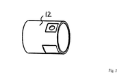
- the measuring nozzle has a base nozzle and a jacket sleeve, wherein the measuring chamber is at least partially formed in a space between the base nozzle and the jacket sleeve.
- the base closes the measuring chamber opposite the passage for the heat exchange fluid.
- the jacket sleeve closes off the measuring chamber from the environment.
- the measuring chamber connection has a measuring chamber connection piece via which the sensor device can be coupled to the measuring chamber.
- the measuring chamber connecting piece can be detachably or non-detachably mounted.
- the heat exchanger device has a plate heat exchanger with a stack of heat transfer plates, with which the mutually closed passages for the heat exchanger fluids are formed.
- the plate heat exchanger has a confining plate that unilaterally defines the stack of heat transfer plates.
- the plate heat exchanger can be of any design. These include in particular sealed, soldered and welded plate heat exchangers.
- a clamping device may be provided which is configured to apply an external clamping pressure to the stack of heat transfer plates.
- a plate heat exchanger is then provided, preferably in sealed form, having the following features: a stacked arrangement comprising a front and a back end plate, at least one end plate of which is a terminal plate, heat exchanger plates interposed between the front and rear end plates; and the back end plate are received and stacked such that voids for receiving a plurality of heat exchange media are formed between the heat exchanger plates, and seal members sealingly disposed the voids and a chuck configured to receive the stacked arrangement for clamping with an external chucking pressure to act upon, wherein the tensioning device, the stacked arrangement is formed encompassing in at least a portion of the stacked arrangement.
- the cross section of the clamping device on the inside is adapted to the outer contour of the stacked arrangement, at least in the at least one corner region, within the scope of customary manufacturing tolerances. It can also be provided that the positive engagement is formed in several or even all corner regions. The latter is given, for example, when the clamping device, the stacked arrangement is formed completely encompassing form-fitting manner.
- the stacked arrangement is provided with two end or boundary plates, which are also referred to as pressure frame plates, which are connected in the outside over the stack of heat transfer or heat exchanger plates protruding areas with tie rods.
- the tie rods are provided with screw threads so that the pressure to be applied to the stack is adjustable.
- a preferred embodiment may provide that the clamping device rests in the at least one form-fitting embraced portion of the stacked arrangement substantially continuously on the outer surface of an associated portion of the stacked arrangement.
- the tensioning device is formed with one or more closed profile elements and / or one or more flexible tension straps, which respectively embrace the stacked arrangement.
- the straps are preferably formed from one of the following materials: steel, plastics and thermoplastics.
- the one or more straps are threaded onto the stacked assembly by mechanical tensioning and / or shrinking.
- the one or more closed profile elements may for example be formed as a square profile or tube. Profile elements in this or other embodiments are available as such in different variants at low cost. In this way, the manufacturing costs are minimized overall.
- the one or more closed profile elements are pushed from the front side to the stacked arrangement with end plate (s) and heat exchanger plates arranged therebetween. This happens in at least one side not yet mounted connections.
- the terminals can then be mounted after sliding the one or more closed profile elements.
- the clamping device is formed with a continuous closed profile element, which extends around the stacked arrangement encompassing over a range of at least 50% of the length of the portion of the stacked arrangement between terminals on the connection plate.
- the continuous closed profile element forms a kind of "belly band" in the region of the stacked arrangement between the terminals.
- the continuous closed profile element extends over a range of at least 75% of the length of the stacked arrangement between the terminals. It is further preferred that the continuous closed profile element covers a length of at least 90% of the area between the terminals.
- the portion of the stacked arrangement between the terminals may be wholly or partially encompassed by one or more closed profile elements.
- the clamping device is formed with a continuous closed profile element, which encompasses the stacked arrangement extends over the entire length of the plate heat exchanger. It can be provided that the clamping device is formed with a plurality of closed profile elements, which in the longitudinal direction of the stacked arrangement all or at least in pairs have a substantially equal width.
- the one or more closed profile elements are formed from a standard profile element. The use of standard profile elements supports a further cost reduction, since such profile elements are available as frequently produced products in various designs at low cost.
- a training provides that wall sections of the one or more closed profile elements are formed as profiled profiles.
- a flat design of the wall sections of the closed profile elements further supports the minimized space requirement of the plate heat exchanger.
- the clamping device is formed with adjustable biasing elements, which are arranged on the one of the several closed profile elements.
- the adjustable biasing elements are formed, for example, by means of screw elements which are screwed in associated threaded portions in the one or more closed profile elements.
- the screw elements can then be screwed in so far that they finally press against the stacked arrangement.
- such screw elements are provided only on the front or only on the back of the stacked arrangement of the closed profile elements. On the opposite side, the stacked arrangement is then pressed flat against the inside of the closed profile element.
- the adjustable biasing elements are configured to initiate the external clamping pressure on the stacked arrangement, preferably substantially symmetrical.
- the adjustable biasing elements are formed at one or all closed profile elements in the transverse direction of the stacked arrangement spaced from each other.
- a training provides that the one or more closed profile elements connecting areas, in which terminals are arranged on the terminal plate, are formed free-standing.
- Fig. 1 shows a schematic representation perspective view of a heat exchanger 1, in which a heat exchanger device is formed with a plate heat exchanger.
- a heat exchanger device is formed with a plate heat exchanger.
- a stack of heat transfer plates 3 is arranged in a designed as a surrounding sleeve clamping device 2.
- Passages for heat exchange fluids are formed in the stack of heat transfer plates 3.
- a connection device 4 with a plurality of connections 4a,..., 4d couples to the passages formed in the stack of heat transfer plates 3, such that, during operation, heat exchange fluids can be supplied and removed via the plurality of connections 4a,..., 4d.
- the connection device 4 has at the connection 4a a measuring stub 5, which is described below with reference to FIGS Fig. 2 to 5 is explained in more detail.
- Fig. 2 shows a perspective view of the measuring stub 5.
- Fig. 3 shows a sectional view of the measuring stub 5. It follows that the measuring stub 5 has a passage 6 between an inlet 7 and an outlet 8. The passage 6 is in operation of the Heat exchanger 1 flows through the heat exchange fluid.
- the passage 6 is formed in a base 9. On a part of the surface 6 facing away from the passage 6 of the base nozzle 9, a measuring chamber 11 is formed, which is closed relative to the environment by means of a jacket sleeve 12. Compared to the passage 6, the measuring chamber 11 is closed by means of the wall of the basic nozzle 9.
- a measuring chamber opening 13 is formed, via which the measuring chamber 11 can be coupled to a sensor device (not shown) in order to detect a temperature-dependent measured variable for the measuring chamber 11 and / or a measuring medium to be introduced therein.
- a measuring chamber connecting piece 14 is arranged in the region of the measuring chamber opening 13, which can be detachably or non-detachably mounted.
- Fig. 4 and 5 show perspective views of the basic nozzle 9 and the jacket sleeve 12th
Landscapes
- Physics & Mathematics (AREA)
- Engineering & Computer Science (AREA)
- Thermal Sciences (AREA)
- Mechanical Engineering (AREA)
- General Engineering & Computer Science (AREA)
- General Physics & Mathematics (AREA)
- Heat-Exchange Devices With Radiators And Conduit Assemblies (AREA)
- Measuring Temperature Or Quantity Of Heat (AREA)
Applications Claiming Priority (1)
| Application Number | Priority Date | Filing Date | Title |
|---|---|---|---|
| DE102012104908A DE102012104908A1 (de) | 2012-06-06 | 2012-06-06 | Wärmetauscher und Messstutzen für Wärmetauscher |
Publications (3)
| Publication Number | Publication Date |
|---|---|
| EP2672216A2 true EP2672216A2 (fr) | 2013-12-11 |
| EP2672216A3 EP2672216A3 (fr) | 2015-08-26 |
| EP2672216B1 EP2672216B1 (fr) | 2018-05-30 |
Family
ID=48607097
Family Applications (1)
| Application Number | Title | Priority Date | Filing Date |
|---|---|---|---|
| EP13170786.1A Not-in-force EP2672216B1 (fr) | 2012-06-06 | 2013-06-06 | Échangeur de chaleur |
Country Status (2)
| Country | Link |
|---|---|
| EP (1) | EP2672216B1 (fr) |
| DE (1) | DE102012104908A1 (fr) |
Cited By (1)
| Publication number | Priority date | Publication date | Assignee | Title |
|---|---|---|---|---|
| CN115585694A (zh) * | 2022-10-12 | 2023-01-10 | 北京航空航天大学江西研究院 | 一种用于毛细管式换热器阵列排管固定的拉杆式框架结构 |
Family Cites Families (8)
| Publication number | Priority date | Publication date | Assignee | Title |
|---|---|---|---|---|
| US1276024A (en) * | 1917-12-04 | 1918-08-20 | Walter S Brittin | Temperature-indicator. |
| US2804773A (en) * | 1955-09-19 | 1957-09-03 | Henze Instr And Valve Inc | Temperature sensing devices |
| US3022670A (en) * | 1959-12-07 | 1962-02-27 | Jr Frank C Sutliffe | Thermo-element |
| SE518475C2 (sv) | 2001-02-20 | 2002-10-15 | Alfa Laval Ab | Plattvärmeväxlare med sensoranordning |
| DE102004006390B4 (de) * | 2004-02-10 | 2006-04-13 | Pewo Energietechnik Gmbh | Rücklauftemperaturbegrenzer mit Startfunktion |
| DE102008037852A1 (de) | 2008-08-15 | 2010-02-18 | Robin Petrick | Plattenwärmetauscher |
| SE533810C2 (sv) * | 2009-06-04 | 2011-01-25 | Alfa Laval Corp Ab | Plattvärmeväxlare med temperatursensor för flödesstyrning |
| DE102011001544A1 (de) * | 2011-03-24 | 2012-09-27 | Gea Wtt Gmbh | Plattenwärmetauscher |
-
2012
- 2012-06-06 DE DE102012104908A patent/DE102012104908A1/de not_active Withdrawn
-
2013
- 2013-06-06 EP EP13170786.1A patent/EP2672216B1/fr not_active Not-in-force
Cited By (1)
| Publication number | Priority date | Publication date | Assignee | Title |
|---|---|---|---|---|
| CN115585694A (zh) * | 2022-10-12 | 2023-01-10 | 北京航空航天大学江西研究院 | 一种用于毛细管式换热器阵列排管固定的拉杆式框架结构 |
Also Published As
| Publication number | Publication date |
|---|---|
| DE102012104908A1 (de) | 2013-12-12 |
| EP2672216B1 (fr) | 2018-05-30 |
| EP2672216A3 (fr) | 2015-08-26 |
Similar Documents
| Publication | Publication Date | Title |
|---|---|---|
| DE112014005441B4 (de) | Koaxiale Ventilanordnung | |
| EP2295886B1 (fr) | Dispositif de chauffage de liquides | |
| WO2014095413A1 (fr) | Élément de mesure hydraulique pourvu d'entrées de pression coplanaires et capteur de pression différentielle pourvu d'un tel élément de mesure | |
| DE102012112457A1 (de) | Massendurchflussmess- oder regelgerät | |
| DE102014203038A1 (de) | Wärmeübertrager | |
| EP2505952B1 (fr) | Échangeur thermique à plaques | |
| DE3737433A1 (de) | Baustein fuer einen kreuzstrom-roehrenwaermeaustauscher und daraus hergestellter waermeaustauscher | |
| EP2423629B1 (fr) | Echangeur thermique à plaques conçu de manière étanche | |
| EP2672216B1 (fr) | Échangeur de chaleur | |
| DE102007020628B4 (de) | Anschlussgarnitur für einen Plattenheizkörper | |
| EP3012553B1 (fr) | Composant pour une installation de chauffage | |
| EP1231450B1 (fr) | Echangeur de chaleur en aluminium | |
| EP2167935B1 (fr) | Dispositif de mesure de la viscosité de masses fondues de matière plastique | |
| DE202008001611U1 (de) | Vorrichtung zur solaren Energiegewinnung, insbesondere Solarkollektor | |
| DE2517186A1 (de) | Temperierelement | |
| DE3316538A1 (de) | Plattenheizkoerper | |
| DE102007052934A1 (de) | Durchlauferhitzer mit einem Sicherheitstemperaturbegrenzer | |
| DE19523047C1 (de) | Elektrischer Durchlauferhitzer für flüssige Medien | |
| DE3200474C2 (de) | Elektrischer Durchlauferhitzer | |
| DE2441991A1 (de) | Vorrichtung zur verbindung von stranggepressten heizkoerpergliedern mit heizmittelsammelrohren | |
| DE202011000636U1 (de) | Pumpenmodul zur Verwendung in einem Verteiler für ein Fußbodenheizungssystem | |
| AT413240B (de) | Anschluss- und verbindungsmodul | |
| EP3418640A1 (fr) | Distributeur pour un échangeur de chaleur à plaques | |
| DE202010010779U1 (de) | Durchlauferhitzer | |
| DE102007059146B3 (de) | Hochdruckwärmetauscher |
Legal Events
| Date | Code | Title | Description |
|---|---|---|---|
| PUAI | Public reference made under article 153(3) epc to a published international application that has entered the european phase |
Free format text: ORIGINAL CODE: 0009012 |
|
| AK | Designated contracting states |
Kind code of ref document: A2 Designated state(s): AL AT BE BG CH CY CZ DE DK EE ES FI FR GB GR HR HU IE IS IT LI LT LU LV MC MK MT NL NO PL PT RO RS SE SI SK SM TR |
|
| AX | Request for extension of the european patent |
Extension state: BA ME |
|
| PUAL | Search report despatched |
Free format text: ORIGINAL CODE: 0009013 |
|
| AK | Designated contracting states |
Kind code of ref document: A3 Designated state(s): AL AT BE BG CH CY CZ DE DK EE ES FI FR GB GR HR HU IE IS IT LI LT LU LV MC MK MT NL NO PL PT RO RS SE SI SK SM TR |
|
| AX | Request for extension of the european patent |
Extension state: BA ME |
|
| RIC1 | Information provided on ipc code assigned before grant |
Ipc: F28F 27/00 20060101AFI20150720BHEP Ipc: G01K 1/14 20060101ALI20150720BHEP Ipc: F28D 9/00 20060101ALI20150720BHEP |
|
| 17P | Request for examination filed |
Effective date: 20151221 |
|
| RBV | Designated contracting states (corrected) |
Designated state(s): AL AT BE BG CH CY CZ DE DK EE ES FI FR GB GR HR HU IE IS IT LI LT LU LV MC MK MT NL NO PL PT RO RS SE SI SK SM TR |
|
| GRAP | Despatch of communication of intention to grant a patent |
Free format text: ORIGINAL CODE: EPIDOSNIGR1 |
|
| INTG | Intention to grant announced |
Effective date: 20171027 |
|
| GRAS | Grant fee paid |
Free format text: ORIGINAL CODE: EPIDOSNIGR3 |
|
| RAP1 | Party data changed (applicant data changed or rights of an application transferred) |
Owner name: KELVION BRAZED PHE GMBH |
|
| GRAA | (expected) grant |
Free format text: ORIGINAL CODE: 0009210 |
|
| AK | Designated contracting states |
Kind code of ref document: B1 Designated state(s): AL AT BE BG CH CY CZ DE DK EE ES FI FR GB GR HR HU IE IS IT LI LT LU LV MC MK MT NL NO PL PT RO RS SE SI SK SM TR |
|
| REG | Reference to a national code |
Ref country code: GB Ref legal event code: FG4D Free format text: NOT ENGLISH |
|
| REG | Reference to a national code |
Ref country code: CH Ref legal event code: EP |
|
| REG | Reference to a national code |
Ref country code: AT Ref legal event code: REF Ref document number: 1004050 Country of ref document: AT Kind code of ref document: T Effective date: 20180615 |
|
| REG | Reference to a national code |
Ref country code: IE Ref legal event code: FG4D Free format text: LANGUAGE OF EP DOCUMENT: GERMAN |
|
| REG | Reference to a national code |
Ref country code: DE Ref legal event code: R096 Ref document number: 502013010234 Country of ref document: DE |
|
| REG | Reference to a national code |
Ref country code: CH Ref legal event code: NV Representative=s name: ISLER AND PEDRAZZINI AG, CH |
|
| REG | Reference to a national code |
Ref country code: SE Ref legal event code: TRGR |
|
| REG | Reference to a national code |
Ref country code: NL Ref legal event code: MP Effective date: 20180530 |
|
| REG | Reference to a national code |
Ref country code: LT Ref legal event code: MG4D |
|
| PG25 | Lapsed in a contracting state [announced via postgrant information from national office to epo] |
Ref country code: NO Free format text: LAPSE BECAUSE OF FAILURE TO SUBMIT A TRANSLATION OF THE DESCRIPTION OR TO PAY THE FEE WITHIN THE PRESCRIBED TIME-LIMIT Effective date: 20180830 Ref country code: FI Free format text: LAPSE BECAUSE OF FAILURE TO SUBMIT A TRANSLATION OF THE DESCRIPTION OR TO PAY THE FEE WITHIN THE PRESCRIBED TIME-LIMIT Effective date: 20180530 Ref country code: LT Free format text: LAPSE BECAUSE OF FAILURE TO SUBMIT A TRANSLATION OF THE DESCRIPTION OR TO PAY THE FEE WITHIN THE PRESCRIBED TIME-LIMIT Effective date: 20180530 Ref country code: BG Free format text: LAPSE BECAUSE OF FAILURE TO SUBMIT A TRANSLATION OF THE DESCRIPTION OR TO PAY THE FEE WITHIN THE PRESCRIBED TIME-LIMIT Effective date: 20180830 Ref country code: CY Free format text: LAPSE BECAUSE OF FAILURE TO SUBMIT A TRANSLATION OF THE DESCRIPTION OR TO PAY THE FEE WITHIN THE PRESCRIBED TIME-LIMIT Effective date: 20180530 Ref country code: ES Free format text: LAPSE BECAUSE OF FAILURE TO SUBMIT A TRANSLATION OF THE DESCRIPTION OR TO PAY THE FEE WITHIN THE PRESCRIBED TIME-LIMIT Effective date: 20180530 |
|
| PG25 | Lapsed in a contracting state [announced via postgrant information from national office to epo] |
Ref country code: RS Free format text: LAPSE BECAUSE OF FAILURE TO SUBMIT A TRANSLATION OF THE DESCRIPTION OR TO PAY THE FEE WITHIN THE PRESCRIBED TIME-LIMIT Effective date: 20180530 Ref country code: HR Free format text: LAPSE BECAUSE OF FAILURE TO SUBMIT A TRANSLATION OF THE DESCRIPTION OR TO PAY THE FEE WITHIN THE PRESCRIBED TIME-LIMIT Effective date: 20180530 Ref country code: LV Free format text: LAPSE BECAUSE OF FAILURE TO SUBMIT A TRANSLATION OF THE DESCRIPTION OR TO PAY THE FEE WITHIN THE PRESCRIBED TIME-LIMIT Effective date: 20180530 Ref country code: GR Free format text: LAPSE BECAUSE OF FAILURE TO SUBMIT A TRANSLATION OF THE DESCRIPTION OR TO PAY THE FEE WITHIN THE PRESCRIBED TIME-LIMIT Effective date: 20180831 |
|
| PG25 | Lapsed in a contracting state [announced via postgrant information from national office to epo] |
Ref country code: NL Free format text: LAPSE BECAUSE OF FAILURE TO SUBMIT A TRANSLATION OF THE DESCRIPTION OR TO PAY THE FEE WITHIN THE PRESCRIBED TIME-LIMIT Effective date: 20180530 |
|
| PG25 | Lapsed in a contracting state [announced via postgrant information from national office to epo] |
Ref country code: PL Free format text: LAPSE BECAUSE OF FAILURE TO SUBMIT A TRANSLATION OF THE DESCRIPTION OR TO PAY THE FEE WITHIN THE PRESCRIBED TIME-LIMIT Effective date: 20180530 Ref country code: EE Free format text: LAPSE BECAUSE OF FAILURE TO SUBMIT A TRANSLATION OF THE DESCRIPTION OR TO PAY THE FEE WITHIN THE PRESCRIBED TIME-LIMIT Effective date: 20180530 Ref country code: CZ Free format text: LAPSE BECAUSE OF FAILURE TO SUBMIT A TRANSLATION OF THE DESCRIPTION OR TO PAY THE FEE WITHIN THE PRESCRIBED TIME-LIMIT Effective date: 20180530 Ref country code: RO Free format text: LAPSE BECAUSE OF FAILURE TO SUBMIT A TRANSLATION OF THE DESCRIPTION OR TO PAY THE FEE WITHIN THE PRESCRIBED TIME-LIMIT Effective date: 20180530 Ref country code: SK Free format text: LAPSE BECAUSE OF FAILURE TO SUBMIT A TRANSLATION OF THE DESCRIPTION OR TO PAY THE FEE WITHIN THE PRESCRIBED TIME-LIMIT Effective date: 20180530 Ref country code: DK Free format text: LAPSE BECAUSE OF FAILURE TO SUBMIT A TRANSLATION OF THE DESCRIPTION OR TO PAY THE FEE WITHIN THE PRESCRIBED TIME-LIMIT Effective date: 20180530 |
|
| PG25 | Lapsed in a contracting state [announced via postgrant information from national office to epo] |
Ref country code: SM Free format text: LAPSE BECAUSE OF FAILURE TO SUBMIT A TRANSLATION OF THE DESCRIPTION OR TO PAY THE FEE WITHIN THE PRESCRIBED TIME-LIMIT Effective date: 20180530 Ref country code: IT Free format text: LAPSE BECAUSE OF FAILURE TO SUBMIT A TRANSLATION OF THE DESCRIPTION OR TO PAY THE FEE WITHIN THE PRESCRIBED TIME-LIMIT Effective date: 20180530 |
|
| REG | Reference to a national code |
Ref country code: DE Ref legal event code: R097 Ref document number: 502013010234 Country of ref document: DE |
|
| REG | Reference to a national code |
Ref country code: BE Ref legal event code: MM Effective date: 20180630 |
|
| REG | Reference to a national code |
Ref country code: IE Ref legal event code: MM4A |
|
| PG25 | Lapsed in a contracting state [announced via postgrant information from national office to epo] |
Ref country code: MC Free format text: LAPSE BECAUSE OF FAILURE TO SUBMIT A TRANSLATION OF THE DESCRIPTION OR TO PAY THE FEE WITHIN THE PRESCRIBED TIME-LIMIT Effective date: 20180530 Ref country code: LU Free format text: LAPSE BECAUSE OF NON-PAYMENT OF DUE FEES Effective date: 20180606 |
|
| PLBE | No opposition filed within time limit |
Free format text: ORIGINAL CODE: 0009261 |
|
| STAA | Information on the status of an ep patent application or granted ep patent |
Free format text: STATUS: NO OPPOSITION FILED WITHIN TIME LIMIT |
|
| GBPC | Gb: european patent ceased through non-payment of renewal fee |
Effective date: 20180830 |
|
| PG25 | Lapsed in a contracting state [announced via postgrant information from national office to epo] |
Ref country code: IE Free format text: LAPSE BECAUSE OF NON-PAYMENT OF DUE FEES Effective date: 20180606 Ref country code: FR Free format text: LAPSE BECAUSE OF NON-PAYMENT OF DUE FEES Effective date: 20180730 |
|
| 26N | No opposition filed |
Effective date: 20190301 |
|
| PG25 | Lapsed in a contracting state [announced via postgrant information from national office to epo] |
Ref country code: SI Free format text: LAPSE BECAUSE OF FAILURE TO SUBMIT A TRANSLATION OF THE DESCRIPTION OR TO PAY THE FEE WITHIN THE PRESCRIBED TIME-LIMIT Effective date: 20180530 Ref country code: BE Free format text: LAPSE BECAUSE OF NON-PAYMENT OF DUE FEES Effective date: 20180630 |
|
| PG25 | Lapsed in a contracting state [announced via postgrant information from national office to epo] |
Ref country code: GB Free format text: LAPSE BECAUSE OF NON-PAYMENT OF DUE FEES Effective date: 20180830 |
|
| PG25 | Lapsed in a contracting state [announced via postgrant information from national office to epo] |
Ref country code: AL Free format text: LAPSE BECAUSE OF FAILURE TO SUBMIT A TRANSLATION OF THE DESCRIPTION OR TO PAY THE FEE WITHIN THE PRESCRIBED TIME-LIMIT Effective date: 20180530 |
|
| PG25 | Lapsed in a contracting state [announced via postgrant information from national office to epo] |
Ref country code: MT Free format text: LAPSE BECAUSE OF FAILURE TO SUBMIT A TRANSLATION OF THE DESCRIPTION OR TO PAY THE FEE WITHIN THE PRESCRIBED TIME-LIMIT Effective date: 20180530 |
|
| PG25 | Lapsed in a contracting state [announced via postgrant information from national office to epo] |
Ref country code: TR Free format text: LAPSE BECAUSE OF FAILURE TO SUBMIT A TRANSLATION OF THE DESCRIPTION OR TO PAY THE FEE WITHIN THE PRESCRIBED TIME-LIMIT Effective date: 20180530 |
|
| PG25 | Lapsed in a contracting state [announced via postgrant information from national office to epo] |
Ref country code: HU Free format text: LAPSE BECAUSE OF FAILURE TO SUBMIT A TRANSLATION OF THE DESCRIPTION OR TO PAY THE FEE WITHIN THE PRESCRIBED TIME-LIMIT; INVALID AB INITIO Effective date: 20130606 Ref country code: PT Free format text: LAPSE BECAUSE OF FAILURE TO SUBMIT A TRANSLATION OF THE DESCRIPTION OR TO PAY THE FEE WITHIN THE PRESCRIBED TIME-LIMIT Effective date: 20180530 |
|
| PG25 | Lapsed in a contracting state [announced via postgrant information from national office to epo] |
Ref country code: MK Free format text: LAPSE BECAUSE OF NON-PAYMENT OF DUE FEES Effective date: 20180530 |
|
| PG25 | Lapsed in a contracting state [announced via postgrant information from national office to epo] |
Ref country code: IS Free format text: LAPSE BECAUSE OF FAILURE TO SUBMIT A TRANSLATION OF THE DESCRIPTION OR TO PAY THE FEE WITHIN THE PRESCRIBED TIME-LIMIT Effective date: 20180930 |
|
| PGFP | Annual fee paid to national office [announced via postgrant information from national office to epo] |
Ref country code: AT Payment date: 20210622 Year of fee payment: 9 Ref country code: SE Payment date: 20210624 Year of fee payment: 9 Ref country code: CH Payment date: 20210624 Year of fee payment: 9 |
|
| PGFP | Annual fee paid to national office [announced via postgrant information from national office to epo] |
Ref country code: DE Payment date: 20210630 Year of fee payment: 9 |
|
| REG | Reference to a national code |
Ref country code: DE Ref legal event code: R119 Ref document number: 502013010234 Country of ref document: DE |
|
| REG | Reference to a national code |
Ref country code: CH Ref legal event code: PL Ref country code: SE Ref legal event code: EUG |
|
| REG | Reference to a national code |
Ref country code: AT Ref legal event code: MM01 Ref document number: 1004050 Country of ref document: AT Kind code of ref document: T Effective date: 20220606 |
|
| PG25 | Lapsed in a contracting state [announced via postgrant information from national office to epo] |
Ref country code: SE Free format text: LAPSE BECAUSE OF NON-PAYMENT OF DUE FEES Effective date: 20220607 Ref country code: LI Free format text: LAPSE BECAUSE OF NON-PAYMENT OF DUE FEES Effective date: 20220630 Ref country code: CH Free format text: LAPSE BECAUSE OF NON-PAYMENT OF DUE FEES Effective date: 20220630 Ref country code: AT Free format text: LAPSE BECAUSE OF NON-PAYMENT OF DUE FEES Effective date: 20220606 |
|
| PG25 | Lapsed in a contracting state [announced via postgrant information from national office to epo] |
Ref country code: DE Free format text: LAPSE BECAUSE OF NON-PAYMENT OF DUE FEES Effective date: 20230103 |