EP2672249A2 - Dispositif d'application d'une force de pression dirigée sur une pluralité d'échantillons - Google Patents
Dispositif d'application d'une force de pression dirigée sur une pluralité d'échantillons Download PDFInfo
- Publication number
- EP2672249A2 EP2672249A2 EP13169768.2A EP13169768A EP2672249A2 EP 2672249 A2 EP2672249 A2 EP 2672249A2 EP 13169768 A EP13169768 A EP 13169768A EP 2672249 A2 EP2672249 A2 EP 2672249A2
- Authority
- EP
- European Patent Office
- Prior art keywords
- pressure
- sample
- samples
- hydraulic cylinder
- hydraulic
- Prior art date
- Legal status (The legal status is an assumption and is not a legal conclusion. Google has not performed a legal analysis and makes no representation as to the accuracy of the status listed.)
- Withdrawn
Links
Images







Classifications
-
- F—MECHANICAL ENGINEERING; LIGHTING; HEATING; WEAPONS; BLASTING
- F04—POSITIVE - DISPLACEMENT MACHINES FOR LIQUIDS; PUMPS FOR LIQUIDS OR ELASTIC FLUIDS
- F04B—POSITIVE-DISPLACEMENT MACHINES FOR LIQUIDS; PUMPS
- F04B1/00—Multi-cylinder machines or pumps characterised by number or arrangement of cylinders
-
- B—PERFORMING OPERATIONS; TRANSPORTING
- B30—PRESSES
- B30B—PRESSES IN GENERAL
- B30B1/00—Presses, using a press ram, characterised by the features of the drive therefor, pressure being transmitted directly, or through simple thrust or tension members only, to the press ram or platen
- B30B1/32—Presses, using a press ram, characterised by the features of the drive therefor, pressure being transmitted directly, or through simple thrust or tension members only, to the press ram or platen by plungers under fluid pressure
-
- G—PHYSICS
- G01—MEASURING; TESTING
- G01N—INVESTIGATING OR ANALYSING MATERIALS BY DETERMINING THEIR CHEMICAL OR PHYSICAL PROPERTIES
- G01N19/00—Investigating materials by mechanical methods
- G01N19/04—Measuring adhesive force between materials, e.g. of sealing tape, of coating
-
- G—PHYSICS
- G01—MEASURING; TESTING
- G01N—INVESTIGATING OR ANALYSING MATERIALS BY DETERMINING THEIR CHEMICAL OR PHYSICAL PROPERTIES
- G01N3/00—Investigating strength properties of solid materials by application of mechanical stress
- G01N3/08—Investigating strength properties of solid materials by application of mechanical stress by applying steady tensile or compressive forces
Definitions
- the invention is in the field of joining, in particular cohesive joining, and relates to a device for simultaneously applying a plurality of samples with identical contact pressure regardless of the height of the samples.
- a test stamp is glued or soldered end face with the respective substrate and after curing of the adhesive or the remelting of a solder deposit strength of the achieved cohesive composite at a defined tensile or shear stress investigated.
- the thickness of different substrates on the other hand also the thickness of an applied adhesive layer or a solder deposit can vary, e.g. depending on the viscosity, the size of particles or fillers contained in the adhesive or contained in a solder paste, the resulting height of different layer constructions with otherwise standardized test punches is subject to certain scattering in addition to normal specimen variations.
- an apparatus and a method for applying a directed pressure force to a plurality of samples while tolerating height differences of the individual samples are proposed.
- a device and according to claim 19 a method for simultaneously applying a predetermined identical contact pressure to a plurality of samples using standardized joining surface modules is proposed, wherein a force exerted on the samples contact pressure in a selected contact pressure range regardless of the sample height and independent of a selected ambient temperature, or operating temperature is.
- adhesive surface module Lötschimodul and sample carrier, test punches or dies are to be simplistically represented by the term joining surface module - regardless of whether it is the intended joint connection to an adhesive bond, a solder joint, a compound by an intermetallic alloy, or another with a Phase transition or phase change associated cohesive connection is.
- sample stands for both a still ungeklocatingen, already glued, one still unsoldered, already remelted or soldered or otherwise cohesively joined or intended for cohesive joining pile.
- sample stands for an assembly comprising a substrate, a respective means for the material-fit joining - or a joining agent or a binder and a joining surface module, wherein the joining surface module has a first side, which is in contact with the joining means in the direction of the substrate ,
- the substrate may be, for example, a solid in the form of a material pattern selected from a ceramic, a glass, a metal, a metallic alloy, a semiconductor, a laminate, a composite, a mineral, a natural or artificial stone, a mineral material, a crystal, a resin or a plastic and in the form of a semifinished product or in the form of a film.
- Adhesive layers, adhesive depots or solder deposits can also result in the use of standardized joining surface modules of identical design and height respectively different sample heights.
- a device for applying a directed pressure force to a plurality of samples wherein a first part of the device has a plurality of receptacles which is adapted to receive a plurality of sufficiently uniform samples ordered and a second part of the device with the first part is connectable so that a plurality of hydraulic cylinders in fluid communication with each other in one of the two parts simultaneously load the joining surface modules in a loading direction with a predetermined and defined for all samples and adjustable, and substantially the same force.
- This force is defined by the hydrostatic pressure reached in hydraulic cylinders. From the knowledge of the hydrostatic pressure and the geometrically defined contact surface between the substrate and the joining surface module and the number of substrates / samples, the contact force or respectively the respective applied contact pressure can be determined.
- Advantages of this embodiment consist in the reliability of findings which are made on samples which are to be subjected to a defined force, possibly a force curve, over a defined period of time using this device.
- the proposed device is advantageously so compact that it can simultaneously accommodate a plurality of samples and thus allows the collection of findings on several samples of different types but similar geometry in parallel.
- Such findings relate, for example, to the strength of adhesive bonds between joining surface module and sample, in particular the comparability of results obtained for the reliability of adhesive bonds or for their optimization.
- Another advantage is the increased sample throughput. To ensure the comparability of test results of different test runs, only an identical hydrostatic pressure of the hydraulic fluid of the hydraulic cylinders communicating with each other is to be ensured. Further advantages result from the use of an adapted pressure control technology or adapted hydraulic fluids.
- a device for applying a directed pressure force to a plurality of samples wherein the first and the second part are connectable or connected to one another by at least one holding element connected to the respective part.
- the respective support elements have mutually corresponding shapes, and / or the support element of the first part has a form corresponding to the support element of the second part, whereby also the support element of the second part has a shape corresponding to the support element of the first part.
- Advantages of this embodiment consist in the ability to easily and easily equip the device with samples, to be able to remove the samples easily and quickly again, and to be able to take apart the device after a successful attempt just as easily again. Any residues of adhesive that may have leaked out of the sample stacks during the test can easily be removed as the inclusion of the joining surface module is easily accessible.
- a device for applying a directed pressure force on a plurality of samples wherein the first part of the device with the second part of the device by holding elements of mutually corresponding shapes via a hinge, via a thread, via a bayonet closure, via a Plug-in rotary armature, via a groove / Nutenstein-coupling or according to the key-lock principle are connected to each other.
- Advantages of this embodiment are the ability to easily and quickly assemble the device and just as easily be able to take it apart again after an attempt.
- a device for applying a directed pressure force to a plurality of samples wherein the Receivers are arranged at least partially in an identical radial distance around the support member around.
- a device for applying a directed pressure force on a plurality of samples wherein an external hydraulic drive is connectable to the part of the device in which the hydraulic cylinders are arranged, so that the hydraulic cylinder via a common hydraulic reservoir with an external hydraulic drive can be moved.
- a device for applying a directed pressure force to a plurality of samples wherein the device is adapted so that the arranged in one of the two parts hydraulic cylinder together acted upon by a directly in the same part movably centrally arranged hydraulic cylinder with hydrostatic pressure are.
- Advantages of this embodiment result from the possibility of a decentralized test procedure and the elimination of necessary external auxiliary equipment for operating the hydraulic cylinder.
- a particular advantage of this embodiment is that the device is compact and not too heavy, so that it can still be easily transported and used by a person in the routine operation of a test laboratory and used. Furthermore, the use of this device is advantageously not bound to a laboratory. The device can thus be used if necessary also mobile as needed and on site.
- a device for applying a directed pressure force to a plurality of samples comprising a screwable clamping device, which is adapted so that a reproducible adjustment of the hydrostatic pressure and / or the pressing force can take place.
- a device for applying a directed pressure force to a plurality of samples the screwable tensioning device having a mark or a scale, and the first part or the second part corresponding to the mark or the scale of the screwable tensioning device marking or Includes scale, which is set up so that a discrete position of the screwable clamping device is reproducibly adjustable.
- a device for applying a directed pressure force to a plurality of samples comprising a micrometer or a micrometer, the proposed screwable clamping device comprising a micrometer or a micrometer, and wherein the screw-type clamping device preferably has a precision thread, so on a scale which is arranged parallel to an axis of the device, the size of a feed of the central hydraulic cylinder and the tensioning device of the hydraulic cylinder can be read.
- the readable size is typically readable in pitches of the screw thread of the screwable clamping device, typically expressed as a whole or half millimeters.
- a second scale is provided along a circumference of the subject first or second part of the proposed apparatus provided with the threaded jig, so as to allow reading of a portion of a full pitch which is only a fraction of a pitch or thread pitch.
- Advantages of this embodiment result from the accuracy of measurement of a length or a path of corresponding fine mechanical precision micrometers, which are often referred to as micrometer, as a micrometer or precision mechanical propulsion.
- the precision micrometer allows precise dosing of the contact pressure.
- a device whose centrally arranged hydraulic cylinder has a central pressure piston.
- the increased ambient temperature may be selected so that it corresponds to the remelting temperature of a solder. Reaching the remelt temperature ensures complete wetting of the surfaces in contact with the solder deposit and ensures a firm metallic bond between the solder and the mating surfaces. Overall, the proposed device allows a standardized test procedure. It improves the reliability of the findings.
- a device which further comprises at least one lever arm with a weight, wherein the weight exerts pressure on the central pressure piston via the lever action.
- This embodiment offers the advantage, for example, that the force exerted on the central hydraulic cylinder is adjustable by the choice of the lever (ratio of load arm to force arm) and the mass of the selected weight. It goes without saying that this device allows independent of an external hydraulic pump usability and the almost unlimited mobility of the device. For example, the weight on the lever arm (load arm) is attached or otherwise secured.
- An essential advantage of this embodiment is that a force exerted on a sample by means of the hydraulic cylinders communicating in the central hydraulic cylinder or in the fluidically communicating hydraulic cylinders is independent of any increase in the volume of this fluid.
- the predetermined pressure force is independent of the temperature set for the correct test procedure (ambient temperature). As explained, the ambient temperature or the temperature of the device itself is adjusted so that the examined joining agent or binder, for example an adhesive or a solder, develops the intended holding strength.
- a device which comprises two lever arms, wherein the two lever arms are arranged opposite each other, so that they exert pressure on the central pressure piston jointly via the lever action with a weight attached to each lever arm.
- This embodiment offers, for example, compared with a device equipped with only one lever arm, the additional advantage of increased stability with identical or higher pressure which can be set via the mass of the weights.
- a device wherein the weight consists of part weights or weight segments, which are fastened to one another or to each other.
- This embodiment of the weight offers the advantage of being able to achieve a different contact pressure as a function of the respectively combined partial weights or weight segments combined with one another, and to be able to rapidly realize different contact pressures.
- different weights can be attached to different positions of the lever arm (load arm) with the same aim.
- a device wherein the total mass of a weight attached to the lever arm is in the range between 1 kg and 10 kg and individual partial weights or weight segments have masses of 100 g up to 5 kg, preferably masses of 500 g to 2 kg.
- a device which further comprises a closable opening for filling the centrally arranged hydraulic cylinder with a liquid, which opening can also be used for emptying the hydraulic cylinder.
- a closable opening for filling the centrally arranged hydraulic cylinder with a liquid, which opening can also be used for emptying the hydraulic cylinder.
- separate filling and outlet openings may also be provided.
- a device for applying a directed pressure force to a plurality of samples wherein a liquid in the hydraulic cylinder is not compressible and is stable in a preferred temperature range for the curing of the adhesive.
- this liquid is selected from: water, an aqueous solution, a hydraulic oil, a silicone oil, a heat transfer fluid from the field of application of solar thermal energy.
- the resulting advantages include aspects of the reliability of the proposed device, since a non-compressible liquid which is stable in the selected temperature range is preferably considered as hydraulic fluid.
- the easy availability, aspects of occupational safety, environmental protection and low costs are beneficial.
- the applied pressure can be transmitted uniformly to the hydraulic cylinders of the individual pressure devices communicating with each other via the central hydraulic cylinder, wherein the pressure applied to the samples in each case can be easily regulated and selectively adjusted in each case via the joining surface modules on the areas of the substrate ,
- a device wherein a distance between a pressure point of a hydraulic cylinder and a pressure surface can be adjusted or determined by a locking nut.
- a device for applying a directional pressing force to a plurality of samples further comprising a pressure indicating device for displaying a pressing force or a hydrostatic pressure.
- Advantages result from the usability of a pressure measuring head or a sensor for automatic data acquisition and data storage as well as from the possibility to measure the applied pressure or to control it via an optionally additional control loop.
- a central signal acquisition and signal processing unit can be provided.
- a device for applying a directed pressure force on a plurality of samples which additionally comprises locking means or a preferably removable holding device, which allows a tilt-free recording and / or the transport of the device with a customized holding means.
- the existing holding device makes it easier to handle and transport the device parts equipped with adhesive (s) or adhesives and samples from and to the dosing device or station.
- a device which further comprises at least one heating element for individually heating a joining surface module received in a test receptacle and / or a joining means in contact with the joining surface module, or a joining means between the respective joining surface module and the joining element Substrate comprises.
- the heating element is arranged in close proximity to the respective sample holder.
- an individual temperature of the sample can be set for the respective sample over a predetermined period of time.
- the heating element that is selected from a resistance heater and an induction coil.
- heating power of these heating elements can be precisely adjusted and metered.
- inductive heating by means of an eddy current can be achieved with an induction coil.
- an adhesive filled with ferromagnetic particles can be selectively heated.
- universal joining surface modules for example joint surfaces provided with a threaded pin module
- the connecting means may for example be selected from an adhesive, an adhesive, a cement, a solder, a metallic solder, a glass solder, or a solder paste or corresponding reservoirs, either during curing, setting, reacting or remelting a cohesive Forming a bond between a substrate and a first side of a bonding surface module in the form of a cured adhesive, a set cement, a remelted solder or an alloy having an intermetallic phase, a polymer, a resin or other homogeneous or heterogeneous solids known to those skilled in the art.
- a corresponding recess such as a threaded hole of the mass body pin of the joint surface module ensures a stable position of the sample stack against a corresponding hydraulic cylinder of the second part of the device when the hydraulic cylinders are in the second part of the device.
- a method for the simultaneous application of a predetermined contact pressure to a plurality of samples or test packs of different heights which further comprises applying at least one layer of an adhesive and at least one sample to a first side of a joining surface module.
- the contact pressure applied to the sample or sample stack is predetermined solely by the area of the (pin) joint surface module and is not influenced by the height of the layer of adhesive and substrate. as may be the case with known Federanpressvorraumen.
- a method for simultaneously applying a predetermined contact pressure to a plurality of samples of different heights is proposed, which further comprises setting a predetermined temperature or a predetermined temperature profile or tempering the device.
- thermosetting adhesives can be tested under defined conditions.
- a method for simultaneously applying a predetermined contact pressure to a plurality of samples of different heights is proposed, wherein the tempering in the range of - 40 to + 500 ° C takes place.
- Advantages of this embodiment are, in particular, that a comparison of results obtained over a wide temperature range is possible. Since the device can be manufactured entirely from metallic or high-temperature-resistant materials due to its robust construction, the temperature capacity is limited only by the heat resistance or the thermal behavior of the hydraulic fluid. This creates a wider workspace than can be achieved using conventional equipment.
- tempering of at least one sample receptacle preferably heating with a heating element, furthermore takes place.
- Advantages of this embodiment result from the possibility of identical material combinations in a sample holding device, comprising in each case a layer of a joining agent applied to the joining surface of a joining surface module, for example an adhesive and a substrate (or sample 50) in contact with this layer at different temperatures to be able to hold each identical contact pressure. This enables a reliable comparison of the determined measured values.
- the method comprises individually measuring the temperature effectively achieved at a sample receptacle with an individual probe.
- Fig. 1 shows a substrate, a standardized joining surface module, the mass body screwed thereto and a guide sleeve.
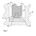
- Fig. 2 shows the view of a longitudinal section through a section of a sample tray, which is equipped with to be joined or glued samples in guide sleeves.
- Fig. 3 shows an embodiment of the proposed device, which is adapted for receiving by means of removable gripping arms.
- Fig. 4 shows an embodiment of the device with a scale display.
- Fig. 5 shows a section of an embodiment with a clamping device in the form of a micrometer or micrometer screw.
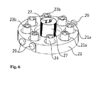
- Fig. 6 shows a designed as a sample plate first part of the device, which is equipped in corresponding receptacles with samples in guide sleeves.
- Fig. 7 shows an embodiment of the invention with hydraulic cylinders and a central hydraulic cylinder (not visible) equipped part of the device with removed Andruckmechanismus.
- Fig. 8 shows the front view of an embodiment of the device with a lever mechanism to compensate for changes in volume of a hydraulic working fluid during heating.
- Fig. 9 shows the front view of the embodiment of the device with a lever mechanism to compensate for changes in volume of a hydraulic working fluid when heated in the raised state, ie at an enlarged by expansion volume of the working fluid in the hydraulic system of the sample holder (slightly exaggerated).
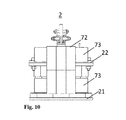
- Fig. 10 shows a side view of the embodiment according to Fig. 8 .
- Fig. 11 shows a perspective view of this embodiment in a front view.
- Fig. 12 shows a perspective view of this embodiment from the back.
- the proposed device 1, 1a essentially comprises two parts 21, 22, wherein a first 21, in the figures as a lower part 21 shown part 21 tray or is formed plate-like and for receiving a plurality of substrates 50 and of substrates 50 or samples and associated guide sleeves 24 is used.
- the second part 22 at least partially covers the first part 21 such that a hydraulic cylinder 25 running in a stationary guide 31 or its pressure point 30 is arranged centrally symmetrically with respect to each sample receptacle 21a provided with the sample and guide sleeve 24. Both parts 21, 22 are detachably connected to each other.
- Fig. 1 by way of example, the geometric relationships of a disk-shaped substrate 50 here, which may also be triangular, quadrangular or polygonal, but in any case advantageously has surfaces which are plane-parallel to one another.
- the substrate 50 may be a semi-finished product into which a smaller object is to be pressed by means of an adapted punch 40, not shown here in detail, or with the aid of an adapted stamping punch 40, not shown here in detail, with an impression should be provided.
- parallelism with the aid of suitable adapted receptacles 21a or inserts for these, not shown here, can be dispensed with.
- one of the surfaces of the substrate has a standardized joining surface module 40 with its first side 41.
- the joining surface module can be screwed into a mass body 23.
- the mass body may be made of a material of particularly high density, for example of a tungsten-copper compound or of a suitable heavy metal alloy.
- the position-fixing mass body is held by a snug-fitting guide sleeve 24 exactly perpendicular to the substrate surface provided with the joining agent.
- the mass body 23 can be inserted before or after screwing with the joining surface module 40 in the guide sleeve 24 so that a front end of the mass body 23 which is provided with an external thread 40a of the joining surface module 40 matching female thread 23a to that with a constricted Through opening 24 a provided side of the guide sleeve 24 has.
- the depth of narrowing of the narrowed passage opening or the wall thickness 24b of the narrowed passage opening 24a is thus matched to the height 40b of the joining surface module 40, without the threaded pin, such that the former is smaller than the latter.
- Fig. 2 shows this in detail using the example of a already in the receptacle 21a serving as a sample plate or lower part first part 21 of the device 1, 1a.
- FIG. 2 the substrate 50 located at the bottom of the receptacle 21a of the first part 21.
- the substrate is provided with a joining agent, for example an adhesive.
- a first part 21 of the device 1, 1a which is initially equipped only with substrates, can be filled by means of a dosing device, a pipetting device or a printing head of a dosing, pipetting or printing station with a predetermined amount of the joining agent 60 - for example a solder paste depot Lotkugeldepot, an adhesive or a grid of droplets of the components of a reactive adhesive mixture are provided.
- the mass body 23, which is free to fit in the guide sleeve 25, can be placed with the joining surface module 40 on a joining means 60.
- the guide sleeve 25 sits with its narrowed passage opening 24a directly on the bare substrate 50.
- the diameter of the restricted passage opening 24a may be wider than the diameter of the joining surface module 40 to avoid contact with the joining means 60.
- an inner leading edge of the restricted passage opening may be chamfered or rounded.
- Fig. 3 shows an exemplary embodiment 1 of the device with arranged symmetrically to an axis 20 locking means 29 and holding means 29 in the assembled state.
- the receptacles 21a of the serving as a sample plate lower or first part 21 of the device 1 are equipped with stabilized by guide sleeves 24 samples.
- the hydraulic cylinders 31 typically each comprise one, in a fixed guide 31 running hydraulic cylinder 25 with central pressure point 30, wherein Fig. 3 only the outer contour of the pressure point 30 can be seen.
- a wing nut 33 which can be screwed onto a central threaded rod 34 is set up to lower and lock the second part 22 of the device 1, 1a near the surface of the sample in front of the highest sample in the lower first part 21 of the device.
- the hydrostatic pressure in a central, with all pressure points 30 having hydraulic cylinders 25 fluidly connected liquid reservoir of the device 1, or its central hydraulic cylinder (hidden), with the help of a about a central axis 20 on an internal thread of the second and upper part 22 of Device 1 screwed arranged clamping device 32 can be adjusted and adjusted reproducible.
- Fig. 4 showed an alternative embodiment 1a of the device with a screw-jig 28, which is provided with a mark 7.
- the marking can be carried out in various ways. The position of the mark to a circumferential scale on the second part 22 is used to adjust the hydrostatic pressure or for calibrating the contact pressure. The circumference 360 degrees circumferential scale or a graduation and the marking can be used together for the reproducible adjustment of contact pressure.
- the respectively completed mechanical advance of the central hydraulic cylinder can be utilized by a tensioning device 28 in the form of a fine adjustment screw or micrometer screw equipped with a fine thread and a ratchet for calibrating the built-up hydrostatic pressure or the contact force reached on the sample side.
- a tensioning device 28 in the form of a fine adjustment screw or micrometer screw equipped with a fine thread and a ratchet for calibrating the built-up hydrostatic pressure or the contact force reached on the sample side.
- a tensioning device 28 in the form of a fine adjustment screw or micrometer screw equipped with a fine thread and a ratchet for calibrating the built-up hydrostatic pressure or the contact force reached on the sample side.
- a tensioning device 28 in the form of a fine adjustment screw or micrometer screw equipped with a fine thread and a ratchet for calibrating the built-up hydrostatic pressure or the contact force reached on the sample side.
- Corresponding scales can either be read vertically at the same time, can be read vertically and horizontal
- Fig. 6 shows a detailed view of the first part 21 of the device 1 with eight concentrically arranged around a connecting element 26 receptacles 21a. Each receptacle 21a is provided with a sample.
- the pressure surfaces 23b of the mass body 23 are supported by the guide sleeves.
- On the side locking means 29 and holding means 29 are provided, which allow a facilitated mounting of the device with a suitable gripping arm. With With the aid of a gripper 35, the device equipped with samples can optionally be transported automatically without tilting.
- the connecting element is designed in the form of a bayonet closure 27.
- the corresponding counterpart of the bayonet closure is located on the second part 22 of the device 1.
- Fig. 7 shows the second and upper part of the device, comprising hydraulic cylinders 25 communicating fluidly with each other, each running in a fixed guide 31, and each having pressure points 30 arranged centrally thereon.
- Fig. 8 shows the front view of a further embodiment 2 of the device with two cooperating levers 70, 71.
- the force exerted by the individual hydraulic cylinders 25 on the samples force is thus independent of the respective temperature of the external environment, which corresponds to a respectively selectively adjusted operating temperature.
- the set temperature corresponds, for example, to a processing temperature of a hot-curing adhesive (adhesive processing temperature).
- Typical adhesive processing temperatures are, for example, in the range of 80 ° C to 250 ° C.
- the processing temperature of a hot melt adhesive s may be at a temperature of 200 ° C.
- a chemically curing adhesive can be cured by supplying heat.
- an individual temperature can also be set in each case.
- electrically operated heating elements are suitable for this individual heating.
- Such a heating element can be based on the principle of resistance heating / Joule heat, but also on the principle of inductive heating.
- an adhesive layer can be selectively heated if the layer contains magnetic particles. Suitable adhesives are, for example, filled with nanoparticles whose diameter is below the intended layer thickness of the adhesive.
- an adhesive layer can be selectively heated without excessively thermal loading of a substrate in contact with the adhesive.
- the adhesive thus filled is heated by an external magnetic field, which is coupled via a coil arranged in or below the sample holder.
- About frequency, pulse rate, if necessary, voltage and current can be set very precisely a certain temperature in the adhesive layer and the applied adhesive "cured from the inside".
- An ambient temperature in the range of 200 ° C causes a significant expansion of the working fluid used in the hydraulic system.
- the resulting contact pressure may differ significantly from an intended and preset pressure, if the expansion of the working fluid (hydraulic fluid) or the container is disregarded.
- a particular advantage of the device provided with at least one lever arm is that the pressure preset over a selected weight or part weights and the length of the lever arm is actually maintained and maintained independent of the ambient temperature during the trial (joining, eg gluing, soldering) becomes.
- the distortion of a preset pressure by an expansion of the working fluid used in a hydraulic cylinder or a strain-induced change in the size of a working cylinder is thus prevented.
- the samples are arranged in the receptacles of the lower part / sample tray 21 (not separately marked here). Then, the first or lower part 21 of the device 2 is connected to the second or upper part 22 of the device 2 via centrally arranged connecting elements 26, 27.
- the hydraulic system is filled with a suitable liquid.
- a working fluid adapted to the test temperature or the respectively set ambient temperature e.g. a hydraulic oil
- a filling or drain plug 76 opening (not shown) filled bubble-free in the hydraulic system.
- the device can be placed in a climatic chamber or oven where the desired temperature is set or already set.
- Fig. 9 shows the frontal view of this embodiment of the device.
- the lever mechanism is shown in the raised state.
- the weights are raised by the temperature-induced expansion of the working fluid in the hydraulic system. If the hydraulic working fluid expands as a result of an increase in the ambient temperature, this would manifest itself without this lever mechanism in a proportional to the volume increase excessive and deviating from the preset value force. This, in turn, may result in a reduced thickness of an adhesive layer of the samples being tested.
- the contact pressure achieved under real test conditions at an ambient temperature of 200 ° C. can deviate significantly from the value preset with a thumbscrew as a result of thermal effects (expansion of the hydraulic fluid, change in volume of the device).
- a temperature of 200 ° C corresponds quite well to an exemplary processing temperature for certain high-temperature adhesives or a remelting temperature of certain solder pastes or solder deposits.
- the described lever mechanism 70, 71 makes it possible to dispense with the use of the measuring screw or clamping device 28 described above.
- the multi-sample pressure device can be used at ambient temperatures corresponding to the processing temperature of high temperature adhesives or solders. The pressure achieved in each case in the hydraulic system-and thus the contact pressure occurring at the sample-is independent of a virtually unavoidable expansion of the working fluid used in the hydraulic system.
- Fig. 10 shows a side view of the embodiment 2 of the device with a lever mechanism.
- the weights attached to the weights 72 73 protrude laterally beyond the width of upper part 22 and lower part 21 out. Again, the compact form of the proposed design is clear.
- FIGS. 11 and 12 show perspective views of an embodiment of the device 2 with a double lever mechanism from and from the back.
- the two lever arms 70, 71 are each constructed here of two interconnected parts. In the illustrated embodiment, the two lever arms engage each other and exert pressure on a central pressure piston or the central hydraulic cylinder 75 via a bearing. Other embodiments, for example, with only one lever arm, are also possible.
- a separately mounted pressure measuring probe 77 can serve for the real-time detection of the pressure prevailing in the hydraulic system.
- Other probes, such as a temperature probe, a thermocouple or a pressure cell can be integrated in a suitable manner in the device.
- FIGS. 11 and 12 The arrangement of the weights 72, 73 built up from elements which are simply connected to one another can be clearly illustrated. Depending on the partial weights 72 or weight segments 73 combined with one another or with each other, a different contact pressure can be achieved. Alternatively, different weights can be attached to different positions of the lever arm (load arm) with the same aim.
- the total mass of a weight attached to the lever arm in the range between 1 kg and 10 kg and be composed of individual partial weights 72, 73 and weight segments of a mass of 100 g up to 5 kg.
- a partial weight 72, 73 suspended on the lever arm can have a mass of 500 g to 2 kg.
- the respective weights attached to the lever arm are divisible and in addition to laterally arranged segments (round pieces) 73 relieved, so that - for example - between 2 kg; 2.5 kg; 4 kg; 4.5 kg and 5 kg mass per side can be varied. Accordingly, about 40 to 100% of the achievable with the respective lever arm maximum pressure force applied.
- the weights may be made of brass, for example.
- connection between a first and a second part via at least one support member 26, 27 is realized, which can be arranged centrally along an imaginary axis 20.
- a mechanical hydraulic pressure mechanism comprises individually extendable hydraulic cylinders 25, each running in a fixed guide 31 which is arranged parallel to the imaginary axis 20. The number and arrangement of the hydraulic cylinders corresponds to the number and arrangement of the receptacles in the first part of the device and thus determines the number of samples that can be handled in a pressing operation.
- the use of the device makes it possible, for example, to improve the reproducibility of conventional methods for testing the strength of adhesive bonds by the applied pressure per sample is independent of the height of the sample or the layer structure of joining surface module / adhesive layer / substrate.
- the pin which is preferably provided with a thread 40a, of a joining surface module 40 is first fixed in the mass body 23 and placed on the substrate provided with the joining substance to be tested.
- an adhesive can be done immediately after its application or at intervals.
- the second part of the device is lowered as far as possible close to the sample surface and locked in place before the highest sample.
- the pressure mechanism itself consists of a central hydraulic fluid reservoir that feeds individual, smaller hydraulic cylinders.
- the hydraulic cylinders gradually come into contact with the samples. After all the hydraulic cylinders are in contact with the samples, the samples are subjected to a uniform pressure. The adhesive pressure can then be increased by further increasing the pressure in the central hydraulic fluid reservoir at the same time for all samples, regardless of the possibly different sample heights defined to the desired target value.
- the described device and the proposed method are more reliable compared to previously known solutions.
- the hitherto customary application of a mass body in the form of a metal plate results in comparable contact pressures only for samples with identical sample height.
- the latter is indispensable for the development of a uniform adhesive thickness and, as a result, a uniform hardening behavior of the adhesive from sample to sample, which in turn is indispensable as a prerequisite for a uniform bond strength from sample to sample.
- samples of typical diameters in the centimeter range or below can be glued simultaneously with identical contact pressure or joined or connected in a materially cohesive or form-fitting manner, whereby microscopic height tolerances as well as certain macroscopic differences (design-related differences in the sample heights) are not restricted with respect to the sample height to lead to reproducibility.
- a significant advantage of the proposed device and the proposed method is that in each case more than one sample of different height can be acted upon by an identical for all samples contact pressure.
- the contact pressure can be set reproducibly, is thus defined and determined by suitable calibration.
- the first side of the joining surface module is arranged plane-parallel to the substrate surface, wherein the gap between joining surface module and substrate completely filled with the joining agent is and remains filled, since the position of the components of the sample is stabilized during the actual joining process.
- the device or the proposed method can be used when a parallel loading of a plurality of objects with an identical contact pressure or force is required, such as for applications in material testing for bonding, in the strength test or in other areas of the Material research and quality management.
- Advantageous combinations of the aforementioned embodiments enable the provision of a device and its use according to a standardisable concept, in particular a test method.
- the standardizability is based on the one hand on the defined and for all samples to be joined identical contact force, regardless of their height.
- advantageous combinations of the embodiments described allow the simultaneous treatment of several samples in one joining operation and the increase of the sample throughput.
Landscapes
- Engineering & Computer Science (AREA)
- Physics & Mathematics (AREA)
- General Health & Medical Sciences (AREA)
- Chemical & Material Sciences (AREA)
- Analytical Chemistry (AREA)
- Biochemistry (AREA)
- Life Sciences & Earth Sciences (AREA)
- General Physics & Mathematics (AREA)
- Immunology (AREA)
- Pathology (AREA)
- Health & Medical Sciences (AREA)
- Mechanical Engineering (AREA)
- General Engineering & Computer Science (AREA)
- Fluid Mechanics (AREA)
- Investigating Strength Of Materials By Application Of Mechanical Stress (AREA)
Applications Claiming Priority (3)
| Application Number | Priority Date | Filing Date | Title |
|---|---|---|---|
| DE102012104925 | 2012-06-06 | ||
| DE102013101434 | 2013-02-13 | ||
| DE102013105150A DE102013105150A1 (de) | 2012-06-06 | 2013-05-21 | Verbesserte Vorrichtung zum Aufbringen einer gerichteten Andruckkraft auf eine Vielzahl von Proben |
Publications (2)
| Publication Number | Publication Date |
|---|---|
| EP2672249A2 true EP2672249A2 (fr) | 2013-12-11 |
| EP2672249A3 EP2672249A3 (fr) | 2017-12-20 |
Family
ID=48577510
Family Applications (1)
| Application Number | Title | Priority Date | Filing Date |
|---|---|---|---|
| EP13169768.2A Withdrawn EP2672249A3 (fr) | 2012-06-06 | 2013-05-29 | Dispositif d'application d'une force de pression dirigée sur une pluralité d'échantillons |
Country Status (3)
| Country | Link |
|---|---|
| US (1) | US9341168B2 (fr) |
| EP (1) | EP2672249A3 (fr) |
| DE (1) | DE102013105150A1 (fr) |
Cited By (2)
| Publication number | Priority date | Publication date | Assignee | Title |
|---|---|---|---|---|
| EP3546918A1 (fr) * | 2018-03-29 | 2019-10-02 | Bundesrepublik Deutschland, vertreten durch den Bundesminister für Wirtschaft und Energie | Dispositif de répartition de charge permettant de charger de manière synchrone une pluralité d'échantillons d'une force de compression définie |
| CN116735360A (zh) * | 2023-07-04 | 2023-09-12 | 盐城立德塑业有限公司 | 一种洗衣机绝缘框架抗压测试装置 |
Families Citing this family (3)
| Publication number | Priority date | Publication date | Assignee | Title |
|---|---|---|---|---|
| CN113418788B (zh) * | 2021-05-07 | 2022-12-27 | 宁波金晟芯影像技术有限公司 | 一种移动式摄像头镜片测压装置 |
| CN115372156B (zh) * | 2022-08-26 | 2024-07-09 | 中国矿业大学 | 一种施加非均质应力加载装置及水力压裂实施方法 |
| CN119880053B (zh) * | 2025-03-25 | 2025-06-10 | 常州市特种涂料有限公司 | 一种便于搅拌罐外表面进行检测的测试装置 |
Citations (1)
| Publication number | Priority date | Publication date | Assignee | Title |
|---|---|---|---|---|
| DE9405764U1 (de) * | 1993-04-26 | 1994-06-01 | Iska Wolfgang Katz Verwaltungs | Pressengetriebenes Werkzeugmodul, insbesondere eine pressengetriebene Querstanz- oder Biegeeinheit |
Family Cites Families (10)
| Publication number | Priority date | Publication date | Assignee | Title |
|---|---|---|---|---|
| US3947204A (en) * | 1972-10-02 | 1976-03-30 | The Dow Chemical Company | Scrapless forming of plastic articles |
| JPS57172234A (en) * | 1981-04-17 | 1982-10-23 | Nippon Steel Corp | Automatic detecting method of adhesive characteristic and its device |
| JPS60173440A (ja) * | 1984-02-20 | 1985-09-06 | Iida Kogyo Kk | 接着力試験機 |
| GB2196437B (en) * | 1986-10-17 | 1991-07-17 | Graphoidal Dev Ltd | Adhesion tester |
| US6729190B1 (en) | 2002-10-28 | 2004-05-04 | Corning Incorporated | Ceramic honeycomb strength testing apparatus |
| DE102004011099B3 (de) * | 2004-03-06 | 2005-12-08 | Robert Bosch Gmbh | Vorrichtung zum Prüfen von Stoffeigenschaften hinsichtlich Zugscherbelastungen, insbesondere zur Prüfung von Klebstoffen |
| DE102004055621B4 (de) * | 2004-11-11 | 2017-08-31 | BAM Bundesanstalt für Materialforschung und -prüfung | Verfahren und Vorrichtung zum Prüfen der Festigkeit einer Verbindung |
| JP4283269B2 (ja) | 2004-12-24 | 2009-06-24 | 山一電機株式会社 | 半導体装置用接続装置、半導体装置キャリア、半導体装置用ソケット、および、プローブカード |
| CA2656276C (fr) * | 2006-06-30 | 2013-09-17 | Airbus Espana, S.L. | Procede pour le controle de qualite d'une liaison collee structurale |
| JP5476106B2 (ja) * | 2009-12-07 | 2014-04-23 | アイダエンジニアリング株式会社 | 電動サーボプレスの制御方法及び制御装置 |
-
2013
- 2013-05-21 DE DE102013105150A patent/DE102013105150A1/de not_active Withdrawn
- 2013-05-29 EP EP13169768.2A patent/EP2672249A3/fr not_active Withdrawn
- 2013-06-06 US US13/911,843 patent/US9341168B2/en not_active Expired - Fee Related
Patent Citations (1)
| Publication number | Priority date | Publication date | Assignee | Title |
|---|---|---|---|---|
| DE9405764U1 (de) * | 1993-04-26 | 1994-06-01 | Iska Wolfgang Katz Verwaltungs | Pressengetriebenes Werkzeugmodul, insbesondere eine pressengetriebene Querstanz- oder Biegeeinheit |
Cited By (2)
| Publication number | Priority date | Publication date | Assignee | Title |
|---|---|---|---|---|
| EP3546918A1 (fr) * | 2018-03-29 | 2019-10-02 | Bundesrepublik Deutschland, vertreten durch den Bundesminister für Wirtschaft und Energie | Dispositif de répartition de charge permettant de charger de manière synchrone une pluralité d'échantillons d'une force de compression définie |
| CN116735360A (zh) * | 2023-07-04 | 2023-09-12 | 盐城立德塑业有限公司 | 一种洗衣机绝缘框架抗压测试装置 |
Also Published As
| Publication number | Publication date |
|---|---|
| US20130327210A1 (en) | 2013-12-12 |
| EP2672249A3 (fr) | 2017-12-20 |
| US9341168B2 (en) | 2016-05-17 |
| DE102013105150A1 (de) | 2013-12-12 |
Similar Documents
| Publication | Publication Date | Title |
|---|---|---|
| EP2718094B1 (fr) | Procédé et dispositif pour la détermination de la répartition de la pression pour le collage | |
| EP3237877B1 (fr) | Dispositif permettant d'effectuer un essai de flexion | |
| EP2672249A2 (fr) | Dispositif d'application d'une force de pression dirigée sur une pluralité d'échantillons | |
| DE102007043364B4 (de) | Halterung zur Aufnahme einer Ultraschallquelle | |
| DE2434910A1 (de) | Probenaufnahmeeinrichtung fuer eine plastizitaetsmessvorrichtung sowie messverfahren unter verwendung der einrichtung | |
| DE68912209T2 (de) | Dielektrisches Analysegerät mit parallelen Platten. | |
| DE3501288C2 (de) | Vorrichtung zum zerstörungsfreien, absoluten Messen von Eigenschaften von festen Stoffen, die aus dem Eindringverhalten eines Prüfkörpers in den Stoff ableitbbar sind | |
| DE102018130719B3 (de) | Verfahren zur Gütebestimmung einer Sinterpastenschicht oder einer Sintermetallschicht und Vorrichtung hierzu | |
| EP3894827B1 (fr) | Système de fixation pour fixer un porte-échantillon sur un dispositif de mesure de force, porte-échantillon et support antagoniste pour un système de fixation de ce type, et dispositif de mesure de force doté d'un tel système de fixation | |
| EP3546918A1 (fr) | Dispositif de répartition de charge permettant de charger de manière synchrone une pluralité d'échantillons d'une force de compression définie | |
| EP3953164A1 (fr) | Procédé et dispositif de mesure servant à mesurer ou à étalonner des ustensiles de presses | |
| EP3798598A1 (fr) | Dispositif, procédé et système de mesure d'une tension propre d'un objet de mesure | |
| DE4204589A1 (de) | Werkstoffpruefvorrichtung fuer zug- oder druckversuche | |
| DE102011054438A1 (de) | Verfahren zur Bestimmung des Trocknungsgrades von Druckbögen | |
| WO2017125269A1 (fr) | Dispositif de mesure, système de mesure et procédé pour déterminer des signaux de mesure pendant un mouvement de pénétration d'un corps de pénétration dans une surface d'un échantillon | |
| DE102010051978B3 (de) | Vorrichtung zur Bestimmung von Niederhaltekräften | |
| DE102006012374A1 (de) | Kratzvorrichtung | |
| DE3702752C2 (fr) | ||
| EP2784476B1 (fr) | Dispositif et procédé destinés au stockage de spécimens | |
| DE4037955A1 (de) | Vorrichtung zur aufnahme von probenbehaeltnissen | |
| DE3216305A1 (de) | Vorrichtung zum messen der dicke von ueberzuegen | |
| EP2355929B1 (fr) | Porte-échantillons et procédé d'obtention de résultats d'analyse comparables par alignement des substances sur une surface homogène | |
| DE102025109085A1 (de) | Vorrichtung zur Biegeprüfung einer Materialprobe | |
| DE102010060563A1 (de) | Verfahren zur spektroskopischen Bestimmung der Konzentration von Inhaltsstoffen in Papieren oder Folien und Probenhalter zur Durchführung des Verfahrens | |
| DE10020042A1 (de) | Vorrichtung zur Bestimmung der Haftfestigkeit von auf Substraten aufgebrachten Beschichtungen |
Legal Events
| Date | Code | Title | Description |
|---|---|---|---|
| PUAI | Public reference made under article 153(3) epc to a published international application that has entered the european phase |
Free format text: ORIGINAL CODE: 0009012 |
|
| AK | Designated contracting states |
Kind code of ref document: A2 Designated state(s): AL AT BE BG CH CY CZ DE DK EE ES FI FR GB GR HR HU IE IS IT LI LT LU LV MC MK MT NL NO PL PT RO RS SE SI SK SM TR |
|
| AX | Request for extension of the european patent |
Extension state: BA ME |
|
| PUAL | Search report despatched |
Free format text: ORIGINAL CODE: 0009013 |
|
| AK | Designated contracting states |
Kind code of ref document: A3 Designated state(s): AL AT BE BG CH CY CZ DE DK EE ES FI FR GB GR HR HU IE IS IT LI LT LU LV MC MK MT NL NO PL PT RO RS SE SI SK SM TR |
|
| AX | Request for extension of the european patent |
Extension state: BA ME |
|
| RIC1 | Information provided on ipc code assigned before grant |
Ipc: G01N 3/08 20060101AFI20171116BHEP Ipc: B30B 1/32 20060101ALI20171116BHEP Ipc: G01N 19/04 20060101ALI20171116BHEP Ipc: F04B 1/00 20060101ALI20171116BHEP |
|
| 17P | Request for examination filed |
Effective date: 20180614 |
|
| RBV | Designated contracting states (corrected) |
Designated state(s): AL AT BE BG CH CY CZ DE DK EE ES FI FR GB GR HR HU IE IS IT LI LT LU LV MC MK MT NL NO PL PT RO RS SE SI SK SM TR |
|
| 17Q | First examination report despatched |
Effective date: 20200616 |
|
| STAA | Information on the status of an ep patent application or granted ep patent |
Free format text: STATUS: THE APPLICATION IS DEEMED TO BE WITHDRAWN |
|
| 18D | Application deemed to be withdrawn |
Effective date: 20200827 |