EP2672336A2 - Flexibles Zahnrad - Google Patents
Flexibles Zahnrad Download PDFInfo
- Publication number
- EP2672336A2 EP2672336A2 EP13167881.5A EP13167881A EP2672336A2 EP 2672336 A2 EP2672336 A2 EP 2672336A2 EP 13167881 A EP13167881 A EP 13167881A EP 2672336 A2 EP2672336 A2 EP 2672336A2
- Authority
- EP
- European Patent Office
- Prior art keywords
- wheel
- blade
- lug
- notch
- pivot axis
- Prior art date
- Legal status (The legal status is an assumption and is not a legal conclusion. Google has not performed a legal analysis and makes no representation as to the accuracy of the status listed.)
- Granted
Links
Images





Classifications
-
- F—MECHANICAL ENGINEERING; LIGHTING; HEATING; WEAPONS; BLASTING
- F16—ENGINEERING ELEMENTS AND UNITS; GENERAL MEASURES FOR PRODUCING AND MAINTAINING EFFECTIVE FUNCTIONING OF MACHINES OR INSTALLATIONS; THERMAL INSULATION IN GENERAL
- F16H—GEARING
- F16H55/00—Elements with teeth or friction surfaces for conveying motion; Worms, pulleys or sheaves for gearing mechanisms
- F16H55/02—Toothed members; Worms
- F16H55/17—Toothed wheels
- F16H55/18—Special devices for taking up backlash
-
- G—PHYSICS
- G04—HOROLOGY
- G04B—MECHANICALLY-DRIVEN CLOCKS OR WATCHES; MECHANICAL PARTS OF CLOCKS OR WATCHES IN GENERAL; TIME PIECES USING THE POSITION OF THE SUN, MOON OR STARS
- G04B13/00—Gearwork
- G04B13/02—Wheels; Pinions; Spindles; Pivots
-
- F—MECHANICAL ENGINEERING; LIGHTING; HEATING; WEAPONS; BLASTING
- F16—ENGINEERING ELEMENTS AND UNITS; GENERAL MEASURES FOR PRODUCING AND MAINTAINING EFFECTIVE FUNCTIONING OF MACHINES OR INSTALLATIONS; THERMAL INSULATION IN GENERAL
- F16H—GEARING
- F16H55/00—Elements with teeth or friction surfaces for conveying motion; Worms, pulleys or sheaves for gearing mechanisms
- F16H55/02—Toothed members; Worms
- F16H55/14—Construction providing resilience or vibration-damping
- F16H55/16—Construction providing resilience or vibration-damping relating to teeth only
-
- G—PHYSICS
- G04—HOROLOGY
- G04B—MECHANICALLY-DRIVEN CLOCKS OR WATCHES; MECHANICAL PARTS OF CLOCKS OR WATCHES IN GENERAL; TIME PIECES USING THE POSITION OF THE SUN, MOON OR STARS
- G04B13/00—Gearwork
- G04B13/02—Wheels; Pinions; Spindles; Pivots
- G04B13/025—Wheels; Pinions; Spindles; Pivots with elastic means between the toothing and the hub of a toothed wheel
-
- G—PHYSICS
- G04—HOROLOGY
- G04B—MECHANICALLY-DRIVEN CLOCKS OR WATCHES; MECHANICAL PARTS OF CLOCKS OR WATCHES IN GENERAL; TIME PIECES USING THE POSITION OF THE SUN, MOON OR STARS
- G04B13/00—Gearwork
- G04B13/02—Wheels; Pinions; Spindles; Pivots
- G04B13/027—Wheels; Pinions; Spindles; Pivots planar toothing: shape and design
-
- G—PHYSICS
- G04—HOROLOGY
- G04B—MECHANICALLY-DRIVEN CLOCKS OR WATCHES; MECHANICAL PARTS OF CLOCKS OR WATCHES IN GENERAL; TIME PIECES USING THE POSITION OF THE SUN, MOON OR STARS
- G04B35/00—Adjusting the gear train, e.g. the backlash of the arbors, depth of meshing of the gears
-
- Y—GENERAL TAGGING OF NEW TECHNOLOGICAL DEVELOPMENTS; GENERAL TAGGING OF CROSS-SECTIONAL TECHNOLOGIES SPANNING OVER SEVERAL SECTIONS OF THE IPC; TECHNICAL SUBJECTS COVERED BY FORMER USPC CROSS-REFERENCE ART COLLECTIONS [XRACs] AND DIGESTS
- Y10—TECHNICAL SUBJECTS COVERED BY FORMER USPC
- Y10T—TECHNICAL SUBJECTS COVERED BY FORMER US CLASSIFICATION
- Y10T74/00—Machine element or mechanism
- Y10T74/19—Gearing
- Y10T74/19623—Backlash take-up
Definitions
- the invention relates to a watch wheel comprising teeth catching clearance each comprising a lug protruding from a pin foot, and a resilient blade projecting from a blade root facing said lug from which it is separated by a ventral notch and of which a lower surface profile on the opposite side to said lug delimits a dorsal notch, said blade root being delimited, towards the axis of pivoting of said wheel, by an inner end of said ventral notch and by an inner end of said dorsal notch.
- the invention also relates to a watchwheel comprising at least one such wheel.
- the invention also relates to a watch movement comprising at least one such wheel.
- the invention also relates to a timepiece comprising at least one such watch movement, and / or at least one such wheel.
- the invention relates to the field of watch mechanisms or scientific measuring apparatus comprising a gear train.
- the invention proposes to define a flexible wheel geometry, feasible in a micro-machinable material, silicon or the like, by a "LIGA” method or the like, and responding well to two problems posed: efficiency and impact resistance.
- the invention relates to a watch wheel having teeth catching play each having a lug protruding a foot pin, and a resilient blade projecting a blade root facing said lug which it is separated by a ventral notch and a lower surface profile of the side opposite said lug delimits a dorsal notch, said blade root being delimited, towards the axis of pivoting of said wheel, by an inner end of said ventral notch and by an inner end of said dorsal notch, characterized in that said lug is forked, and comprises a first tooth and a second tooth flanking a recess, said first tooth and said second tooth being each much more rigid than said elastic blade.
- said inner end of said dorsal notch is located closer to said axis than said inner end of said ventral notch, and extends, on the side of said axis, under said pin foot or under the extension internal geometry of said ventral notch to said pivot axis.
- the invention also relates to a clockwork comprising at least one such wheel, characterized in that said wheel cooperates in meshing with an opposing pinion whose teeth comprise a zone of maximum section arranged to cooperate in driving support with a part external, substantially radial with respect to said pivot axis of said wheel, a said pin or said blade.
- the invention also relates to a watch movement comprising at least one such wheel.
- the invention also relates to a timepiece comprising at least one such watch movement, and / or at least one such wheel.
- the invention relates to the field of watch mechanisms or scientific measuring apparatus comprising a gear train.
- the invention proposes to define a flexible wheel geometry, achievable in a micro-machinable material, silicon or the like, by a method "LIGA” or the like, and ensuring both good performance and good impact resistance.
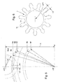
- the invention relates to a watch wheel with teeth 2 to compensate for play.
- Each tooth 2 has a lug 3 protruding from a lug foot 31, and a resilient blade 4 projecting from a blade root 41. opposite this lug 3, from which it is separated by a ventral notch 5.
- This blade 4 has a lower profile 43 on the opposite side to this lug 3, this intrados profile 43 delimits a dorsal notch 6.
- the foot of blade 41 is delimited, towards the pivot axis D of the wheel 10, by an inner end 51 of the ventral notch 5 and by an inner end 61 of the dorsal notch 6.
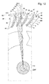
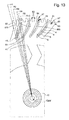
- FIG. 11 to 14 illustrate a particular version, in which the outer portion 34 of the lug 3 is forked, and has a first tooth 81 and a second 85 surrounding a hollow 87, these two teeth 81 and 85 being, each, much stiffer than the blade 4.
- the antagonist wheel 7 meshes then, every two times with a flexible blade 4, and every other time with one of the teeth 81 or 85 of the lug 3, as can be seen in the example of FIG. figure 11 , for a small second display.
- the distal end 47 of the elastic blade 4, and those of the teeth 81 and 85, are contained in the same cylinder centered on the pivot axis of the flexible wheel 10, and preferably all these distal ends are tangent to this same cylinder and have the same maximum radial dimension.
- the inner end 61 of the dorsal notch 6 is situated closer to the axis D than the inner end 51, and extends, on the side of this axis D, under this foot of lug 31 or under the internal extension 52 of this ventral notch 5 towards the axis of pivot D.
- extension 52 only the geometric extension, curvilinear, the median profile of the ventral notch, shown on the figures by a double interrupted line, and not a component or a particular profile of the wheel 10.
- this wheel 10 for a clockwork mechanism, comprises, on the periphery of a wheel body 11, a plurality of teeth with a variable geometry 2 with clearance adjustment.
- Each of these teeth 2 comprises at least one lug 3 attached cantilevered to the wheel body 11 by a lug foot 31, and at least one elastic blade 4 attached cantilevered to the wheel body 11 by a blade root 41: this blade 4 is positioned facing such a pin 3 from which it is separated by a ventral notch 5.
- the elastic blade 4 extends between an extrados profile 42 on the side of this lug 3 and a lower profile 43 on the opposite side to this lug 3.
- the intrados profile 43 delimits a dorsal notch 6, which separates the blade 4 from the remainder of the wheel 10
- the blade root 41 is delimited, on the one hand, by an inner end 51 of the ventral notch 5 on the side of the pivot axis D of the wheel 10, and on the other hand by an internal end 61 of the dorsal notch 6.
- the inner end 61 of the dorsal notch 6 is located closer to the axis Pivot D that the inner end 51 of the ventral notch 5. And the inner end 61 of the dorsal notch 6 extends, on the side of the pivot axis D, under the foot of pin 31 or under the internal extension 52 of the ventral notch 5 towards the pivot axis D.
- the constraints of making such a wheel 10 micro-machinable material require to design the ventral notches 5, as the dorsal notches 6, radiated at their inner ends, respectively 51 and 61.
- the minimum value Rmin1 of this radius end is defined by the nature of the material and the thickness of the board.
- the Rmin2 value of any radius of curvature is also defined by the nature of the material and the thickness of the board.
- the figures 2 and 8 illustrate the inner ends 51 and 61 of the ventral and dorsal slots 6, which are radiated with respective value radii R1 and R2, which are necessarily both greater than the values Rmin1 and Rmin2.
- each part of a tooth 2 in a simplifying assumption where the board is of constant thickness, depends essentially on the length and the width of the part concerned.
- the length of the lug 3, since its lug foot 31, and that of the blade 4, from its blade root 41, are similar. It can be simplified by exposing that the cube of the jettison determines the force necessary to obtain a given deflection at the end of the blade or the lug. For example, if the ratio of the width of the lug LE to that of the blade LL is four, the ratio of the forces is 64.
- the lug 3 has a lower profile 36 which is similar to the extrados profile 42 of the blade 4, and an extrados profile 37 which is similar to the intrados profile 43 of the blade 4 , as visible on the figure 2 .
- the relative parallelism under stress between the external pin and blade profiles gives the wheel 10 a better stability during shocks than the existing flexible wheels.
- the width LL of the blades 4 is conditioned by the aspect ratio. And, in the preferred case where all the teeth 2 of the same wheel 10 are joined, as visible on the figure 1 the width of the dorsal notch 6 is limited by the peripheral distribution of the teeth 2 on the wheel. On the figures 1 and 2 is illustrated a particular variant, wherein the width LL of the blade 4 is constant from the blade root 41 to its distal end 47, where the blade 4 is simply radiated, a radius greater than or equal to Rmin2.
- the width of the dorsal notch 6, in the free state without stress, is close to or equal to that of the blade 4.
- the positions of the inner ends 51 and 61 of the ventral notches 5 and dorsal 6 are dimensioned and positioned so that the lug 3 has a minimum deformation in normal service, and that it can be bent only in case of reception of a force applied much higher than normal, especially in case of shock.
- the width LE, in the plane of the wheel 10, of the lug 3 at its lug foot 31, is greater than three times, and preferably greater than six times the corresponding width LL of the blade 4 at the level of of his blade foot 41.
- the lug 3 has a width that changes little along its length, and which, in the contact zone, at a so-called outer portion 34 of this pin 3, with an antagonistic pinion 7 in a gear train 100 in which the wheel 10 is incorporated, is still greater than five times the corresponding width of the blade 4 at a zone of inflection 48 that it comprises, and which constitutes its preferred contact zone with such a pinion 7.
- FIG. 3 may comprise a degressive width of the lug 3, since its foot 31 towards its distal end 35.
- the important thing is that the lug 3 has a large width at its base, at the level of the lug foot 3, because this zone sees the most important stresses during a shock.
- the positioning of the ends 51 and 61 on the same radius value with respect to the pivot axis D is to be avoided, since it would give too much flexibility to both the pin 3 and the blade 4: the blade 4 no longer corresponds to the aspect ratio and the blade 4 can no longer be manufactured, and the pin 3 would be too flexible, that is to say it would have a normal operating flexibility, which does not is not desired for maintaining good performance. It is therefore preferable that the distance between the end 51 of the ventral notch 5, and the pivot axis D, is different from the distance between the end 61 of the dorsal notch 6, and this same axis D.
- the offset of the end radius R1 of the ventral notch 5 can not be performed on the side of the blade 4, due to the limit constraint imposed by the aspect ratio. It can therefore be performed only on the side of the pin 3, as visible on the preferred embodiment of the figure 2 .
- the offset of the end radius R2 of the dorsal notch 6 can not be carried out on the side of the blade 4, because of the limit constraint imposed by the aspect ratio. It can therefore be performed only on the side of the pin 3, as visible on the preferred embodiment of the figure 2 . But it is necessary to maintain the rigidity of the pin 3 in meshing operation Therefore, according to the invention, the radius R2 is positioned "under" the radius R1, c ', and thus it is undesirable to locally create too much weakness of the pin foot 31. that is, closer to the pivot axis D than the radius R1. This reduces the weakening of the pin 3. In addition, the eventual impact, brought to the bottom of the dorsal notch 6 then has an effect in a substantially radial direction, and then in full matter.
- the foot 31 of the lug 3 is weakened, firstly at the radius R1 at the inner end 51 of the ventral notch 5, and secondly at the radius R2 of the end internal 61 of the dorsal notch 6, which is located closer to the axis D than the end 51.
- This progressive attenuation maintains the resistance of the lug 3 in normal operation, and thus to ensure the good performance of the cog, while providing him with just enough flexibility in case of shock.
- the gear train supports a large second hand, important unbalance: the weakening of the foot of pin 31 according to the invention can withstand a usual shock, such as a fall of the room time, according to the usual experimental values, not detailed here.
- the flexible blade 4 flexes, its inner portion 44 tends to pivot about the blade root 41, and the distal end 47 is rotated about a point about one third of the length of the blade 4, between the inner portion 4 and the central zone 45, and once this rotation is applied, the intrados profiles 36 of the lug 3 and 42 of the lower surface of the blade 4 are preferably substantially parallel to one another. to the other.
- each tooth 2 is separated from its neighbor by a dorsal notch 6.
- each tooth 2 comprises such a lug 3 and such a blade 4.
- An embodiment with more components is theoretically possible, but the width of the components is limited by the process of obtaining and respect of the aspect ratio, and the design of a tooth 2 only two components, lug 3 and blade 4, allows an optimal realization, as well as sufficient strength of these components.
- the dorsal notch 6 extends between the lug 3 of a tooth 2, and the blade 4 of the tooth 2 adjacent to the previous one.
- the ventral notch 5 has substantially parallel edges
- the lug 3 comprises, between the lug foot 31 and a central zone 33, a substantially rectilinear inner portion 32 forming an angle ⁇ E of between 10 ° and 30 °, preferably between 15 ° and 20 °, with a radial end of the pivot axis D.
- This lug 3 further comprises, between the central zone 33 and its distal end 35 farthest from the pivot axis D, an outer portion 34 extending substantially radially with respect to the pivot axis D.
- the blade 4 comprises, between the blade root 41 and a central zone 45, a substantially rectilinear inner portion 44 forming an angle ⁇ L of between 10 ° and 30 °, preferably between 15 and 20 °, with a radial exit of the pivot axis D, and, between the central zone 45 and its distal end 47 farthest from the pivot axis D, an outer portion 46 extending substantially radially relative to the pivot axis D.
- This angle ⁇ L allows, when a pinion 7 or an impeller of the wheel 10 exerts a bearing force on the distal end 47 of the blade 4, to increase the lever arm relative to the foot 41 of the blade 4 .
- an arrow symbolizes the force applied by a tooth of the rigid pinion 7 on the flexible blade 4 t, and a double line shows the lever arm on which is exerted this thrust force.
- angles ⁇ E and ⁇ L are of neighboring value, or equal; in particular a value of 15 ° gives good results.
- the inner end 51 of the ventral notch 5 is radiated with a first radius R1.
- the inner end 61 of the dorsal notch 6 is radiated with a second radius R2 of greater value than that of the first radius R1.
- the dorsal notch 6 has a profile which follows, near its inner end 61, a third radius R3 of greater value than that of the second radius R2, so as to passing the dorsal notch 6 between the pivot axis D and the inner end 51 of the ventral notch 5.
- the blade 4 comprises, between the blade root 41 and a central zone 45, a substantially straight inner portion 44 forming an angle ⁇ L between 10 ° and 30 ° with a radial stem from the pivot axis D.
- the blade 4 further comprises, between the central zone 45 and its distal end 47 furthest from the pivot axis D, an outer portion 46 extending substantially radially with respect to this pivot axis D, up to an inflection zone 48 between a concave portion defined by the inner portion 44 and the outer portion 46 on the one hand, and a convex portion 49 on the other hand to the distal end 47.
- This convex portion 49 is arranged to cooperate in support abutment on a distal end 35 of the lug 3.
- the invention offers, again, the advantage of being insensitive to variations in the center distance between the pivot axis D of the wheel 10 and the pivot axis ⁇ PR of an antagonistic gear 7.
- the board has a thickness of between 0.10 mm and 0.18 mm.
- the variant illustrated in Figures 3 and 4 is designed along the same lines as that of the figure 1 , and to bring the aspect ratio of the value 5 as close as possible.
- the torque and the impact resistance of these two variants are similar.
- the variant of the figure 3 has 90 teeth, when that of the figure 1 has 99, and the thickness of the variant of the figure 3 is 0.12 mm, when that of the figure 1 is 0.15 mm.
- the depth and slope of the ventral and dorsal notches are optimized for good behavior, both in normal meshing and shock.
- the inner portions 44 and 32 of the blade 4 and the lug 3 are substantially linear from the respective feet 41 and 31, while the blade 4 and the lug 3 of the variant of the figure 1 have a profile closer to an arc of a circle or parabola, in their inner parts 44 and 32, continuing in their middle parts 45 and 33.
- the choice of an aspect ratio of 5.5 for the variant of the figure 3 is compatible with a series production, and in this case is used with a board thickness of 0.12 mm.
- the value of center distance E is 2.78 mm and admits a variation of +/- 0.03 mm.
- the rigid pinion 7 of 11 teeth has a modulus of 0.052, its maximum tooth width LD is 0.073 mm over a radius of 0.286 mm, and the maximum radius RH of this pinion is 0.35 mm.
- the wheel 99 of 99 teeth has a maximum radius of the blade 4 RA of 2.64 mm, a maximum radius of the pin 3 RB of 2.63 mm, an RC meshing radius of 2.574 mm, a radius of ER ventral notch end of 2.23 mm, and a 2.19 mm RF dorsal notch end radius.
- the width LE of the lug 3 is 0.070 mm, the width LL of the blade 4 is 0.022 mm.
- the radius of the blade 4 at its inflection zone 48 is 0.062 mm, this blade 4 still has at its distal end 47 a concave radius of 0.020 mm arranged to bear on the distal end 35 of the lug 3.
- the invention also relates to a clockwork train 100 comprising at least one such wheel 10 cooperating in meshing with an opposing gear 7, whose teeth 71 comprise a zone of maximum section 72 arranged to cooperate in driving support with an outer portion, substantially radial relative to the pivot axis D of the wheel 10, a lug 3 or a blade 4 of this wheel 10, as visible on the figure 2 .
- a preferred application is to obtain a clockwork gear without play.
- a particular application is that of small counters, such as a small second, which are not stretched in the gear train, and which are free to move in the gear set. The invention thus avoids stabilization by friction, spring or magnet, to stabilize a floating needle.
- the zone of maximum section 72 cooperates with the wheel 10 at a radius corresponding to that of the inflection zone 48 of the blade 4.
- a first tooth 81 directly faces the distal end 47 of the elastic blade 4, and adopts on a first side a concave profile 84 complementary to the convex profile 49 of this distal end 47, so as to allow a bearing cooperation on a relatively large area, when the elastic blade 4, under the action of a tooth 71 of a counter-wheel 7, is folded towards the lug 3 concerned.
- the opposite flank of this first tooth 81 comprises a profile 83, in particular in involute of circle or similar, which is arranged to cooperate with the teeth 71 of the wheel 7, as visible on the figure 11 or 14 .
- This wheel version comprising assemblies each consisting of a flexible blade 4 and such a forked lug 3 ensures general performance of the movement, in terms of walking, amplitude, and wear resistance, and especially good shock resistance, which is greatly improved.
- the wear and aging behavior is even better than that of the variants of the Figures 1 to 9 , especially with regard to the counter-wheel and the pivots.
- the improvement of the wear resistance is here realized, compared to the variants of the Figures 1 to 9 by the removal of one flexible arm out of two. It can be further improved by the coating of the toothing with a layer of gold to improve its tribological properties, by reducing stress in the meshing, by reducing the arming of the flexible arms.
- the configuration of the figure 14 is designed for the training of a needle calendar by the flexible board constituting the wheel 1.
- this wheel 10 advantageously comprises small hooks 89 at the end of the rigid teeth 81 which work with the elastic blades 4, the goal being to have the right side of the elastic blade 4 which has a first opening 91 significantly larger than the second opening 92 on the other side, as visible on the figure 14 .
- the teeth 71 of the counter-wheel 7 are easily placed in the correct location.
- the flexible wheel 10 according to the invention is designed to work in both directions.
- the figure 11 illustrates an example of application with such a wheel 10, which is engaged with two gears: a center pinion 701, from which the torque to be transmitted.
- This pinion 701 drives the wheel 10, which in turn drives a pinion of small second 702, on which is driven a small second needle.
- the toothing of the wheel 10 does not operate in the same way with the center pinion 701 as with the small second pinion 702.
- the elastic blades 4 are always deformed as far as possible, until that they touch the rigid part constituted by the nearest tooth 81, and it is then necessary that this contact not be at the origin of jamming, in particular when the center distance is at the minimum of the tolerance while in the second case, the elastic blades 4 do not come into contact with the rigid parts 81 or 85, except in the case of impact. Of course, it must be that in both meshes, the game is always zero.
- the design methodology is complex, and requires lengthy simulations and iterations. Starting from standard rigid profiles, one places oneself at the maximum center distance, and one draws a form of elastic blade which cancels the game. The verification by simulation concerns all the angular positions with this center distance, which one checks that the game is null , and the profile of the elastic blade is modified to achieve this first condition. The following check is for simulation in both directions of rotation; in particular, when the counterwheel 7 is driving, it is verified that the elastic blade 4 comes to rest on the tooth which constitutes the rigid part, and that the contact does not cause jamming or undesirable stresses in the elastic blade. This simulation is to be performed in all the angular positions, and at the different distances between the minimum spacing and the maximum center distance. The editing of the profile is conducted as many times as necessary to achieve the desired result.
- the flexible blade 4 occupies a variable position in the gap between the two closest rigid teeth 81 and 85.
- the invention also relates to a watch movement 200 comprising at least one such wheel 100.
- the invention also relates to a timepiece 300 comprising at least one watch movement 200, or / and at least one such wheel 100.
Landscapes
- Physics & Mathematics (AREA)
- General Physics & Mathematics (AREA)
- Engineering & Computer Science (AREA)
- General Engineering & Computer Science (AREA)
- Mechanical Engineering (AREA)
- Gears, Cams (AREA)
- Retarders (AREA)
Priority Applications (1)
| Application Number | Priority Date | Filing Date | Title |
|---|---|---|---|
| EP13167881.5A EP2672336B1 (de) | 2012-06-04 | 2013-05-15 | Flexibles Zahnrad |
Applications Claiming Priority (2)
| Application Number | Priority Date | Filing Date | Title |
|---|---|---|---|
| EP12170705.3A EP2672335B1 (de) | 2012-06-04 | 2012-06-04 | Flexibles Zahnrad |
| EP13167881.5A EP2672336B1 (de) | 2012-06-04 | 2013-05-15 | Flexibles Zahnrad |
Publications (3)
| Publication Number | Publication Date |
|---|---|
| EP2672336A2 true EP2672336A2 (de) | 2013-12-11 |
| EP2672336A3 EP2672336A3 (de) | 2016-07-06 |
| EP2672336B1 EP2672336B1 (de) | 2018-08-15 |
Family
ID=48325544
Family Applications (2)
| Application Number | Title | Priority Date | Filing Date |
|---|---|---|---|
| EP12170705.3A Active EP2672335B1 (de) | 2012-06-04 | 2012-06-04 | Flexibles Zahnrad |
| EP13167881.5A Active EP2672336B1 (de) | 2012-06-04 | 2013-05-15 | Flexibles Zahnrad |
Family Applications Before (1)
| Application Number | Title | Priority Date | Filing Date |
|---|---|---|---|
| EP12170705.3A Active EP2672335B1 (de) | 2012-06-04 | 2012-06-04 | Flexibles Zahnrad |
Country Status (5)
| Country | Link |
|---|---|
| US (1) | US9234572B2 (de) |
| EP (2) | EP2672335B1 (de) |
| JP (1) | JP5616486B2 (de) |
| CN (1) | CN103454895B (de) |
| RU (1) | RU2606192C2 (de) |
Families Citing this family (14)
| Publication number | Priority date | Publication date | Assignee | Title |
|---|---|---|---|---|
| JP6220757B2 (ja) * | 2014-09-16 | 2017-10-25 | 本田技研工業株式会社 | 内接式遊星歯車装置 |
| DE102015105524B4 (de) * | 2015-04-10 | 2024-01-18 | Wittenstein Se | Getriebe |
| EP3208666B1 (de) | 2016-02-19 | 2018-11-21 | Blancpain SA | Uhrenrad mit spielnachstellung |
| CH712261B1 (fr) * | 2016-03-16 | 2020-11-30 | Gfpi S A | Système d'affichage pour pièce d'horlogerie. |
| EP3244094B1 (de) * | 2016-05-12 | 2023-08-16 | Rolex Sa | Zahnrad für uhrwerk |
| EP3273307B1 (de) * | 2016-07-19 | 2025-04-30 | Nivarox-FAR S.A. | Bauteil für uhrwerk |
| CH712973B1 (de) * | 2016-09-23 | 2023-12-29 | Bucherer Ag | Tourbillon und Uhr mit Tourbillon. |
| DE102017011025B3 (de) | 2017-09-25 | 2018-10-31 | Dirk Dornblüth | Zahnrad für Uhrwerk |
| EP3489766B1 (de) * | 2017-11-27 | 2025-11-05 | Montres Breguet S.A. | Mechanismus zur korrektur einer bewegungsfunktion einer uhr |
| DE102018008956A1 (de) * | 2018-11-14 | 2020-05-14 | Lubas Maschinen Gmbh | Zahnrad |
| EP3686462B1 (de) * | 2019-01-28 | 2021-06-09 | IMS Gear SE & Co. KGaA | Zahnrad zur verwendung in einem zahnradgetriebe, zahnradpaarung eines zahnradgetriebes sowie zahnradgetriebe mit einer derartigen zahnradpaarung |
| CH715945B1 (fr) * | 2019-03-01 | 2025-05-15 | Rolex Sa | Engrenage horloger |
| US20230003291A1 (en) * | 2021-06-30 | 2023-01-05 | Optisys, Inc. | Compliant anti-backlash gear |
| CH720788A1 (de) * | 2023-05-16 | 2024-11-29 | Richemont Int Sa | Spielaufhebendes Zahnrad für Uhrmechanismen |
Citations (1)
| Publication number | Priority date | Publication date | Assignee | Title |
|---|---|---|---|---|
| EP2112567A1 (de) | 2008-04-21 | 2009-10-28 | Rolex Sa | Getriebe mit Spielkompensation für Uhrmechanismus |
Family Cites Families (10)
| Publication number | Priority date | Publication date | Assignee | Title |
|---|---|---|---|---|
| EP1380772A1 (de) * | 2002-07-10 | 2004-01-14 | Jean-Marc Wiederrecht | Zahnradgetriebe mit Überlastungsschutz |
| JP4470163B2 (ja) * | 2003-09-03 | 2010-06-02 | 株式会社エンプラス | 成形プラスチック歯車及びこれを使用した間歇回転伝達機構、成形プラスチック歯車の使用方法 |
| EP1555584A1 (de) * | 2004-01-13 | 2005-07-20 | Rolex S.A. | Gezähntes Drehteil für die Einholung des Spiels, Getriebe, und die Benutzung dieses Getriebes |
| DE102004037540B4 (de) * | 2004-08-03 | 2008-05-29 | Micromotion Gmbh | Getriebering eines Spannungswellengetriebes |
| EP2003522B1 (de) * | 2007-06-12 | 2012-11-28 | Chopard Manufacture SA | Zahnrad mit Spielnachstellung für Getriebe, insbesondere für Uhren |
| EP2257719A4 (de) * | 2008-03-10 | 2011-07-27 | Andrew Nowicki | Drehmomenthandhabungszahnrad mit an flexiblen armen montierten zähnen |
| GB0821985D0 (en) | 2008-12-03 | 2009-01-07 | Rolls Royce Plc | A gear |
| EP2354597B1 (de) * | 2010-02-02 | 2012-07-04 | Patek Philippe SA Genève | Triebfeder mit Spielnachstellung |
| CH702629A8 (fr) * | 2010-02-02 | 2011-09-30 | Patek Philippe Sa Geneve | Mobile à rattrapage de jeu et pièce d'horlogerie munie d'un tel mobile. |
| DE202011101577U1 (de) * | 2011-04-27 | 2011-11-10 | Petra Damasko | Zahnradanordnung, insbesondere für mechanische Uhrwerke, mechanisches Uhrwerk sowie Uhr |
-
2012
- 2012-06-04 EP EP12170705.3A patent/EP2672335B1/de active Active
-
2013
- 2013-05-15 EP EP13167881.5A patent/EP2672336B1/de active Active
- 2013-05-31 US US13/906,847 patent/US9234572B2/en active Active
- 2013-06-03 RU RU2013125577A patent/RU2606192C2/ru active
- 2013-06-04 JP JP2013117638A patent/JP5616486B2/ja active Active
- 2013-06-04 CN CN201310218449.0A patent/CN103454895B/zh active Active
Patent Citations (1)
| Publication number | Priority date | Publication date | Assignee | Title |
|---|---|---|---|---|
| EP2112567A1 (de) | 2008-04-21 | 2009-10-28 | Rolex Sa | Getriebe mit Spielkompensation für Uhrmechanismus |
Also Published As
| Publication number | Publication date |
|---|---|
| EP2672336A3 (de) | 2016-07-06 |
| CN103454895A (zh) | 2013-12-18 |
| JP2013250272A (ja) | 2013-12-12 |
| RU2606192C2 (ru) | 2017-01-10 |
| EP2672335B1 (de) | 2016-11-02 |
| US20130333504A1 (en) | 2013-12-19 |
| JP5616486B2 (ja) | 2014-10-29 |
| RU2013125577A (ru) | 2014-12-10 |
| US9234572B2 (en) | 2016-01-12 |
| HK1192334A1 (zh) | 2014-08-15 |
| EP2672335A1 (de) | 2013-12-11 |
| CN103454895B (zh) | 2016-08-10 |
| EP2672336B1 (de) | 2018-08-15 |
Similar Documents
| Publication | Publication Date | Title |
|---|---|---|
| EP2672336B1 (de) | Flexibles Zahnrad | |
| EP2917788B1 (de) | Verfahren zur herstellung eines multistabilen flexiblen elements | |
| EP1921518B1 (de) | Montageelement, das dehnbare Strukturen in Form von aufeinander liegenden Plättchen umfasst, und mit diesem Element ausgerüstete Uhr | |
| EP2897000B1 (de) | Wendegetriebe für Uhr | |
| EP3765922B1 (de) | Uhr | |
| EP3042250B1 (de) | Triebfeder einer uhr mit spielnachstellung | |
| EP3489766B1 (de) | Mechanismus zur korrektur einer bewegungsfunktion einer uhr | |
| CH706624A2 (fr) | Roue à denture flexible. | |
| EP1921516A1 (de) | Montageelement, das zwei Reihen von dehnbaren Strukturen umfasst, und dieses Element umfassende Uhr | |
| CH708553B1 (fr) | Mobile horloger à rattrapage de jeu. | |
| EP3786720B1 (de) | Uhrkomponente zur aufnahme eines organs durch einpressen | |
| CH720210B1 (fr) | Mouvement horloger comprenant un mécanisme de commande de quantième | |
| EP3845973B1 (de) | Uhrwerk, das für den antrieb in einer variablen anzahl von schritten konzipiert ist | |
| EP3629101B1 (de) | Uhranzeigemechanismus | |
| CH720214B1 (fr) | Mécanisme de commande de quantième d'un mouvement horloger | |
| CH716774B9 (fr) | Dispositif horloger de couplage et d'indexation. | |
| EP4407384A1 (de) | Sicherheitsmodul für einen ewigen kalendermechanismus einer uhrwerke | |
| EP4325303A1 (de) | Mechanismus eines immerwährenden kalenders mit konzentrischen nocken | |
| EP3492779B1 (de) | Kupplungsrad mit spielnachstellung | |
| CH717664B1 (fr) | Pièce d'horlogerie comprenant un dispositif de commande étanche. | |
| EP3783444A1 (de) | Uhrwerkmechanismus, der eine blockiervorrichtung umfasst | |
| CH715864B1 (fr) | Organe de blocage pour un mouvement horloger. | |
| HK1192334B (en) | Wheel with a flexible toothing |
Legal Events
| Date | Code | Title | Description |
|---|---|---|---|
| PUAI | Public reference made under article 153(3) epc to a published international application that has entered the european phase |
Free format text: ORIGINAL CODE: 0009012 |
|
| AK | Designated contracting states |
Kind code of ref document: A2 Designated state(s): AL AT BE BG CH CY CZ DE DK EE ES FI FR GB GR HR HU IE IS IT LI LT LU LV MC MK MT NL NO PL PT RO RS SE SI SK SM TR |
|
| AX | Request for extension of the european patent |
Extension state: BA ME |
|
| RAP1 | Party data changed (applicant data changed or rights of an application transferred) |
Owner name: OMEGA SA |
|
| PUAL | Search report despatched |
Free format text: ORIGINAL CODE: 0009013 |
|
| AK | Designated contracting states |
Kind code of ref document: A3 Designated state(s): AL AT BE BG CH CY CZ DE DK EE ES FI FR GB GR HR HU IE IS IT LI LT LU LV MC MK MT NL NO PL PT RO RS SE SI SK SM TR |
|
| AX | Request for extension of the european patent |
Extension state: BA ME |
|
| RIC1 | Information provided on ipc code assigned before grant |
Ipc: F16H 55/16 20060101ALI20160602BHEP Ipc: G04B 13/02 20060101ALI20160602BHEP Ipc: G04B 35/00 20060101AFI20160602BHEP |
|
| STAA | Information on the status of an ep patent application or granted ep patent |
Free format text: STATUS: REQUEST FOR EXAMINATION WAS MADE |
|
| 17P | Request for examination filed |
Effective date: 20170109 |
|
| RBV | Designated contracting states (corrected) |
Designated state(s): AL AT BE BG CH CY CZ DE DK EE ES FI FR GB GR HR HU IE IS IT LI LT LU LV MC MK MT NL NO PL PT RO RS SE SI SK SM TR |
|
| STAA | Information on the status of an ep patent application or granted ep patent |
Free format text: STATUS: EXAMINATION IS IN PROGRESS |
|
| 17Q | First examination report despatched |
Effective date: 20170626 |
|
| GRAP | Despatch of communication of intention to grant a patent |
Free format text: ORIGINAL CODE: EPIDOSNIGR1 |
|
| STAA | Information on the status of an ep patent application or granted ep patent |
Free format text: STATUS: GRANT OF PATENT IS INTENDED |
|
| INTG | Intention to grant announced |
Effective date: 20180406 |
|
| RIN1 | Information on inventor provided before grant (corrected) |
Inventor name: STOECKLI, THOMAS Inventor name: KRAEHENBUEHL, DAVID BENJAMIN Inventor name: KLINGER, LAURENT |
|
| GRAS | Grant fee paid |
Free format text: ORIGINAL CODE: EPIDOSNIGR3 |
|
| GRAA | (expected) grant |
Free format text: ORIGINAL CODE: 0009210 |
|
| STAA | Information on the status of an ep patent application or granted ep patent |
Free format text: STATUS: THE PATENT HAS BEEN GRANTED |
|
| AK | Designated contracting states |
Kind code of ref document: B1 Designated state(s): AL AT BE BG CH CY CZ DE DK EE ES FI FR GB GR HR HU IE IS IT LI LT LU LV MC MK MT NL NO PL PT RO RS SE SI SK SM TR |
|
| REG | Reference to a national code |
Ref country code: CH Ref legal event code: EP Ref country code: GB Ref legal event code: FG4D Free format text: NOT ENGLISH Ref country code: AT Ref legal event code: REF Ref document number: 1030476 Country of ref document: AT Kind code of ref document: T Effective date: 20180815 |
|
| REG | Reference to a national code |
Ref country code: IE Ref legal event code: FG4D Free format text: LANGUAGE OF EP DOCUMENT: FRENCH |
|
| REG | Reference to a national code |
Ref country code: DE Ref legal event code: R096 Ref document number: 602013041921 Country of ref document: DE |
|
| REG | Reference to a national code |
Ref country code: NL Ref legal event code: MP Effective date: 20180815 |
|
| REG | Reference to a national code |
Ref country code: LT Ref legal event code: MG4D |
|
| REG | Reference to a national code |
Ref country code: AT Ref legal event code: MK05 Ref document number: 1030476 Country of ref document: AT Kind code of ref document: T Effective date: 20180815 |
|
| PG25 | Lapsed in a contracting state [announced via postgrant information from national office to epo] |
Ref country code: GR Free format text: LAPSE BECAUSE OF FAILURE TO SUBMIT A TRANSLATION OF THE DESCRIPTION OR TO PAY THE FEE WITHIN THE PRESCRIBED TIME-LIMIT Effective date: 20181116 Ref country code: NL Free format text: LAPSE BECAUSE OF FAILURE TO SUBMIT A TRANSLATION OF THE DESCRIPTION OR TO PAY THE FEE WITHIN THE PRESCRIBED TIME-LIMIT Effective date: 20180815 Ref country code: NO Free format text: LAPSE BECAUSE OF FAILURE TO SUBMIT A TRANSLATION OF THE DESCRIPTION OR TO PAY THE FEE WITHIN THE PRESCRIBED TIME-LIMIT Effective date: 20181115 Ref country code: BG Free format text: LAPSE BECAUSE OF FAILURE TO SUBMIT A TRANSLATION OF THE DESCRIPTION OR TO PAY THE FEE WITHIN THE PRESCRIBED TIME-LIMIT Effective date: 20181115 Ref country code: IS Free format text: LAPSE BECAUSE OF FAILURE TO SUBMIT A TRANSLATION OF THE DESCRIPTION OR TO PAY THE FEE WITHIN THE PRESCRIBED TIME-LIMIT Effective date: 20181215 Ref country code: AT Free format text: LAPSE BECAUSE OF FAILURE TO SUBMIT A TRANSLATION OF THE DESCRIPTION OR TO PAY THE FEE WITHIN THE PRESCRIBED TIME-LIMIT Effective date: 20180815 Ref country code: RS Free format text: LAPSE BECAUSE OF FAILURE TO SUBMIT A TRANSLATION OF THE DESCRIPTION OR TO PAY THE FEE WITHIN THE PRESCRIBED TIME-LIMIT Effective date: 20180815 Ref country code: FI Free format text: LAPSE BECAUSE OF FAILURE TO SUBMIT A TRANSLATION OF THE DESCRIPTION OR TO PAY THE FEE WITHIN THE PRESCRIBED TIME-LIMIT Effective date: 20180815 Ref country code: LT Free format text: LAPSE BECAUSE OF FAILURE TO SUBMIT A TRANSLATION OF THE DESCRIPTION OR TO PAY THE FEE WITHIN THE PRESCRIBED TIME-LIMIT Effective date: 20180815 Ref country code: SE Free format text: LAPSE BECAUSE OF FAILURE TO SUBMIT A TRANSLATION OF THE DESCRIPTION OR TO PAY THE FEE WITHIN THE PRESCRIBED TIME-LIMIT Effective date: 20180815 |
|
| PG25 | Lapsed in a contracting state [announced via postgrant information from national office to epo] |
Ref country code: AL Free format text: LAPSE BECAUSE OF FAILURE TO SUBMIT A TRANSLATION OF THE DESCRIPTION OR TO PAY THE FEE WITHIN THE PRESCRIBED TIME-LIMIT Effective date: 20180815 Ref country code: HR Free format text: LAPSE BECAUSE OF FAILURE TO SUBMIT A TRANSLATION OF THE DESCRIPTION OR TO PAY THE FEE WITHIN THE PRESCRIBED TIME-LIMIT Effective date: 20180815 Ref country code: LV Free format text: LAPSE BECAUSE OF FAILURE TO SUBMIT A TRANSLATION OF THE DESCRIPTION OR TO PAY THE FEE WITHIN THE PRESCRIBED TIME-LIMIT Effective date: 20180815 |
|
| PG25 | Lapsed in a contracting state [announced via postgrant information from national office to epo] |
Ref country code: PL Free format text: LAPSE BECAUSE OF FAILURE TO SUBMIT A TRANSLATION OF THE DESCRIPTION OR TO PAY THE FEE WITHIN THE PRESCRIBED TIME-LIMIT Effective date: 20180815 Ref country code: EE Free format text: LAPSE BECAUSE OF FAILURE TO SUBMIT A TRANSLATION OF THE DESCRIPTION OR TO PAY THE FEE WITHIN THE PRESCRIBED TIME-LIMIT Effective date: 20180815 Ref country code: CZ Free format text: LAPSE BECAUSE OF FAILURE TO SUBMIT A TRANSLATION OF THE DESCRIPTION OR TO PAY THE FEE WITHIN THE PRESCRIBED TIME-LIMIT Effective date: 20180815 Ref country code: IT Free format text: LAPSE BECAUSE OF FAILURE TO SUBMIT A TRANSLATION OF THE DESCRIPTION OR TO PAY THE FEE WITHIN THE PRESCRIBED TIME-LIMIT Effective date: 20180815 Ref country code: ES Free format text: LAPSE BECAUSE OF FAILURE TO SUBMIT A TRANSLATION OF THE DESCRIPTION OR TO PAY THE FEE WITHIN THE PRESCRIBED TIME-LIMIT Effective date: 20180815 Ref country code: RO Free format text: LAPSE BECAUSE OF FAILURE TO SUBMIT A TRANSLATION OF THE DESCRIPTION OR TO PAY THE FEE WITHIN THE PRESCRIBED TIME-LIMIT Effective date: 20180815 |
|
| REG | Reference to a national code |
Ref country code: DE Ref legal event code: R097 Ref document number: 602013041921 Country of ref document: DE |
|
| PG25 | Lapsed in a contracting state [announced via postgrant information from national office to epo] |
Ref country code: SM Free format text: LAPSE BECAUSE OF FAILURE TO SUBMIT A TRANSLATION OF THE DESCRIPTION OR TO PAY THE FEE WITHIN THE PRESCRIBED TIME-LIMIT Effective date: 20180815 Ref country code: DK Free format text: LAPSE BECAUSE OF FAILURE TO SUBMIT A TRANSLATION OF THE DESCRIPTION OR TO PAY THE FEE WITHIN THE PRESCRIBED TIME-LIMIT Effective date: 20180815 Ref country code: SK Free format text: LAPSE BECAUSE OF FAILURE TO SUBMIT A TRANSLATION OF THE DESCRIPTION OR TO PAY THE FEE WITHIN THE PRESCRIBED TIME-LIMIT Effective date: 20180815 |
|
| PLBE | No opposition filed within time limit |
Free format text: ORIGINAL CODE: 0009261 |
|
| STAA | Information on the status of an ep patent application or granted ep patent |
Free format text: STATUS: NO OPPOSITION FILED WITHIN TIME LIMIT |
|
| 26N | No opposition filed |
Effective date: 20190516 |
|
| PG25 | Lapsed in a contracting state [announced via postgrant information from national office to epo] |
Ref country code: SI Free format text: LAPSE BECAUSE OF FAILURE TO SUBMIT A TRANSLATION OF THE DESCRIPTION OR TO PAY THE FEE WITHIN THE PRESCRIBED TIME-LIMIT Effective date: 20180815 |
|
| PG25 | Lapsed in a contracting state [announced via postgrant information from national office to epo] |
Ref country code: MC Free format text: LAPSE BECAUSE OF FAILURE TO SUBMIT A TRANSLATION OF THE DESCRIPTION OR TO PAY THE FEE WITHIN THE PRESCRIBED TIME-LIMIT Effective date: 20180815 |
|
| REG | Reference to a national code |
Ref country code: BE Ref legal event code: MM Effective date: 20190531 |
|
| PG25 | Lapsed in a contracting state [announced via postgrant information from national office to epo] |
Ref country code: LU Free format text: LAPSE BECAUSE OF NON-PAYMENT OF DUE FEES Effective date: 20190515 |
|
| PG25 | Lapsed in a contracting state [announced via postgrant information from national office to epo] |
Ref country code: TR Free format text: LAPSE BECAUSE OF FAILURE TO SUBMIT A TRANSLATION OF THE DESCRIPTION OR TO PAY THE FEE WITHIN THE PRESCRIBED TIME-LIMIT Effective date: 20180815 |
|
| PG25 | Lapsed in a contracting state [announced via postgrant information from national office to epo] |
Ref country code: IE Free format text: LAPSE BECAUSE OF NON-PAYMENT OF DUE FEES Effective date: 20190515 |
|
| PG25 | Lapsed in a contracting state [announced via postgrant information from national office to epo] |
Ref country code: BE Free format text: LAPSE BECAUSE OF NON-PAYMENT OF DUE FEES Effective date: 20190531 |
|
| PG25 | Lapsed in a contracting state [announced via postgrant information from national office to epo] |
Ref country code: PT Free format text: LAPSE BECAUSE OF FAILURE TO SUBMIT A TRANSLATION OF THE DESCRIPTION OR TO PAY THE FEE WITHIN THE PRESCRIBED TIME-LIMIT Effective date: 20181215 |
|
| PG25 | Lapsed in a contracting state [announced via postgrant information from national office to epo] |
Ref country code: CY Free format text: LAPSE BECAUSE OF FAILURE TO SUBMIT A TRANSLATION OF THE DESCRIPTION OR TO PAY THE FEE WITHIN THE PRESCRIBED TIME-LIMIT Effective date: 20180815 |
|
| PG25 | Lapsed in a contracting state [announced via postgrant information from national office to epo] |
Ref country code: MT Free format text: LAPSE BECAUSE OF FAILURE TO SUBMIT A TRANSLATION OF THE DESCRIPTION OR TO PAY THE FEE WITHIN THE PRESCRIBED TIME-LIMIT Effective date: 20180815 Ref country code: HU Free format text: LAPSE BECAUSE OF FAILURE TO SUBMIT A TRANSLATION OF THE DESCRIPTION OR TO PAY THE FEE WITHIN THE PRESCRIBED TIME-LIMIT; INVALID AB INITIO Effective date: 20130515 |
|
| PG25 | Lapsed in a contracting state [announced via postgrant information from national office to epo] |
Ref country code: MK Free format text: LAPSE BECAUSE OF FAILURE TO SUBMIT A TRANSLATION OF THE DESCRIPTION OR TO PAY THE FEE WITHIN THE PRESCRIBED TIME-LIMIT Effective date: 20180815 |
|
| P01 | Opt-out of the competence of the unified patent court (upc) registered |
Effective date: 20230701 |
|
| PGFP | Annual fee paid to national office [announced via postgrant information from national office to epo] |
Ref country code: DE Payment date: 20250423 Year of fee payment: 13 |
|
| PGFP | Annual fee paid to national office [announced via postgrant information from national office to epo] |
Ref country code: GB Payment date: 20250423 Year of fee payment: 13 |
|
| PGFP | Annual fee paid to national office [announced via postgrant information from national office to epo] |
Ref country code: FR Payment date: 20250423 Year of fee payment: 13 |
|
| PGFP | Annual fee paid to national office [announced via postgrant information from national office to epo] |
Ref country code: CH Payment date: 20250601 Year of fee payment: 13 |