EP2672590B1 - Coque électriquement isolante, dispositif d'isolation électrique comprenant une telle coque isolante et panneau d'appareillage de commutation associé - Google Patents
Coque électriquement isolante, dispositif d'isolation électrique comprenant une telle coque isolante et panneau d'appareillage de commutation associé Download PDFInfo
- Publication number
- EP2672590B1 EP2672590B1 EP12171309.3A EP12171309A EP2672590B1 EP 2672590 B1 EP2672590 B1 EP 2672590B1 EP 12171309 A EP12171309 A EP 12171309A EP 2672590 B1 EP2672590 B1 EP 2672590B1
- Authority
- EP
- European Patent Office
- Prior art keywords
- shell
- insulating
- half shell
- electrically insulating
- central part
- Prior art date
- Legal status (The legal status is an assumption and is not a legal conclusion. Google has not performed a legal analysis and makes no representation as to the accuracy of the status listed.)
- Active
Links
Images




Classifications
-
- H—ELECTRICITY
- H02—GENERATION; CONVERSION OR DISTRIBUTION OF ELECTRIC POWER
- H02B—BOARDS, SUBSTATIONS OR SWITCHING ARRANGEMENTS FOR THE SUPPLY OR DISTRIBUTION OF ELECTRIC POWER
- H02B11/00—Switchgear having carriage withdrawable for isolation
- H02B11/02—Details
- H02B11/04—Isolating-contacts, e.g. mountings or shieldings
-
- H—ELECTRICITY
- H01—ELECTRIC ELEMENTS
- H01B—CABLES; CONDUCTORS; INSULATORS; SELECTION OF MATERIALS FOR THEIR CONDUCTIVE, INSULATING OR DIELECTRIC PROPERTIES
- H01B17/00—Insulators or insulating bodies characterised by their form
- H01B17/26—Lead-in insulators; Lead-through insulators
-
- H—ELECTRICITY
- H02—GENERATION; CONVERSION OR DISTRIBUTION OF ELECTRIC POWER
- H02G—INSTALLATION OF ELECTRIC CABLES OR LINES, OR OF COMBINED OPTICAL AND ELECTRIC CABLES OR LINES
- H02G5/00—Installations of bus-bars
- H02G5/06—Totally-enclosed installations, e.g. in metal casings
-
- H—ELECTRICITY
- H02—GENERATION; CONVERSION OR DISTRIBUTION OF ELECTRIC POWER
- H02B—BOARDS, SUBSTATIONS OR SWITCHING ARRANGEMENTS FOR THE SUPPLY OR DISTRIBUTION OF ELECTRIC POWER
- H02B1/00—Frameworks, boards, panels, desks, casings; Details of substations or switching arrangements
- H02B1/14—Shutters or guards for preventing access to contacts
-
- H—ELECTRICITY
- H02—GENERATION; CONVERSION OR DISTRIBUTION OF ELECTRIC POWER
- H02B—BOARDS, SUBSTATIONS OR SWITCHING ARRANGEMENTS FOR THE SUPPLY OR DISTRIBUTION OF ELECTRIC POWER
- H02B3/00—Apparatus specially adapted for the manufacture, assembly, or maintenance of boards or switchgear
Definitions
- the present disclosure relates to an electrically insulating shell, to an electrically insulating device comprising such insulating shell, and to a related switchgear panel.
- the electrically insulating shell and related electrically insulating device according to the present disclosure are particularly suitable for being used inside the cabinet of electric switchgear panels, in particular when retrofitting existing switchgear panels, and will be described by making particular reference to such applications, without intending however to limit their possible broader applications.
- Such insulating devices are devised basically to electrically insulate the conductor to which they are associated from the surrounding environment; in addition, depending on the specific applications, they are usually required to guarantee a good mechanical robustness and/or thermal stability for a quite long life-time.
- Patent document EP0880208 discloses a modular wiring unit wherein a plate member to which it is possible to connect the wiring that leads to an electrical distribution line.
- the plate member comprises two pluralities of recesses for connection to the distribution line by means of plugs and to a further adjacent plate member, and has a base member inside which there is positioned a laminated pack for insertion of pins of the plugs and a covering member coupled to the base member.
- Patent document US 4,723,917 discloses a low voltage distribution device which comprises a structure in a molded insulating material comprising two rectangular walls connected by a transversal partition. Rails are embedded in the transversal partition which serve on one side to support bus-bars for current inflow and on the other side they constitute power connections.
- Patent document EP2148403 discloses a plastic raceway whose cover has a wall elongated along a longitudinal direction encircled by two lateral rims; each one of the rims is conformed in such a manner to be clipped on lateral wings of a U-shaped gutter support and is provided with a set of incipient ruptures periodically spaced in the longitudinal direction. The incipient ruptures contain an opening traversing each of the rims, where the incipient ruptures are entirely contained in back of the wing.
- the distance between the pre-existing contact pieces of the electric circuit into which the circuit breaker has to be inserted may be totally different and unsuitable with respect to the distance of the corresponding input and output connection contacts of the circuit breaker; hence, the installer should form "ad hoc" paths for electrically connecting each contact of the circuit breaker to the respective contact piece of the associated circuit.
- an insulating device should have first a structure adapted to be applied to the specific conductive path to which is it associated; but, for having a greater market appeal, it should have an own structure applicable to different paths at least within the same cabinet and it should also fit with limits and constraints imposed by the surrounding parts of the panel, without imposing substantial modifications to its structure.
- the present disclosure is aimed at providing a solution which allows satisfying at least some of the above indicated needs and in particular it provides an electrically insulating shell suitable to be operatively associated to an electrical conductor comprising one or more pieces connected together, the insulating shell comprising a first half shell and a second half shell devised to be mutually connected together, characterized in that said first half shell and said second half shell are shaped so as to define, once connected together, a central part delimiting a substantially closed space encasing inside it a corresponding first portion of said electrical conductor, a first hollow portion protruding from a first side of said central part, said first hollow portion being in space communication with the inner space of said closed central part and adapted to surround a corresponding second portion of said electrical conductor suitable for connection to a contact piece of an electric circuit, and a second hollow portion protruding from said central part from a second side opposite to said first side, said second hollow portion being in space communication with the inner space of said closed central part and adapted to surround a corresponding third
- the present disclosure also encompasses an electrically insulating device characterized in that it comprises one or more insulating shells as defined by the related appended claims and described hereinafter, and an insulating plate having a central part perforated with one or more holes inside each of which the second portion of a corresponding insulating shell is suitable to be inserted.
- the present disclosures also relates to a switchgear panel comprising a cabinet, a circuit breaker positioned inside said cabinet and suitable to be electrically connected in input and output to an associated electrical circuit along electrical connection paths formed each by one or more conductive pieces, characterized in that it comprises at least one electrically insulating shell as defined by the related appended claims and described hereinafter, said at least one insulating shell being operatively positioned along one of said conductive path so as to electrically insulate at least a portion of the path from the surrounding environment.
- a switchgear panel comprising a cabinet, a circuit breaker positioned inside said cabinet and having a plurality of connection contacts suitable to be electrically connected each to a corresponding contact piece of an associated electrical circuit along a respective connection path formed by one or more conductive pieces, characterized in that it comprises an electrically insulating device as defined by the related appended claims and described hereinafter, and wherein the insulating plate of the insulating device comprises one or more side walls which protrude transversally from a central part of the insulating plate and are mechanically connected to a further component of the panel.
- any component as a whole, or to any part of a component, or to a whole combinations of components, or even to any part of a combination of components, it has to be understood that it means and encompasses the structure, and/or configuration and/or shape and/or positioning of the related component or part thereof, or combinations of components or part thereof, such term refers to.
- Figures 1 and 2 show an electrically insulating shell 100 according to the present disclosure under assembling- and assembled with- an electrical conductor 200, respectively.
- Such an electrical conductor 200 may comprise one or more pieces connected together according to various applications; for example, the exemplary conductor 200 depicted in the attached figures, comprises a first portion 201, e.g. link-shaped, a second portion 202, e.g. cylindrical or tubular, which protrudes transversely from a first side of the first portion 201, and a third portion 203, for instance tubular or cylindrical, which protrudes from a second side of the first shaped portion opposite to the first side.
- the conductor 200 depicted in the figures has to be understood only for illustrative and non-limiting purposes; for example, the shape, number, and/or the relative position of the parts may change.
- the insulating shell 100 comprises a first half shell 1 and a second half shell 2 devised to be mutually connected together and shaped so as to define, once connected together (as illustrated in figure 2 ): a central part 3 delimiting a substantially closed space encasing inside it a corresponding first portion of the electrical conductor 200, e.g. the first portion 201; a first hollow portion 4 protruding transversely from a first side of the central part 3, for instance at an end portion thereof.
- the cavity of the first hollow portion 4 is in space communication or continuity with the inner space of the closed central part 3 and is adapted to surround an associated second portion of the electrical conductor 200, e.g. the second portion 202.
- the two shells 1 and 2 once connected define also a second hollow portion 5 which protrudes transversely from a second side opposite to said first side of the central part 3; for instance and as illustrated in the figures, the second hollow portion 5 is located at a second end of the central part 3 opposite to its first end where the first hollow portion 4 is provided.
- the cavity of the second hollow portion 5 is also in space communication or continuity with the inner space of the closed central part 3 and is adapted to surround the corresponding third portion of the electrical conductor 200, e.g. the third portion 203.
- the insulating shell 100 defines a continuous path (formed by the cavity of the first hollow portion 4, the inner space encased by the central part 3 which has the form of a box-like element, and the cavity of the second hollow portion 5) along and inside which a conductor is placed and electrically insulated from the surrounding environment.
- at least one of the first half shell 1 and the second half shell 2 comprises a shaped body having a plurality of reference notches 30 adapted to allow cutting away portions of the respective shaped body itself, thus allowing to easily adjust the size of the insulating shell 100, and in particular of its central part 3 according to the specific application.
- first half shell 1 and the second half shell 2 comprise first coupling means 6 and second coupling means 7, respectively, which are suitable to mutually engage so as to mechanically connect each other the first half shell 1 and the second half shell 2 in a snap-fit way.
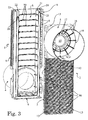
- the first half shell 1 comprises a shaped body having a first base wall 8, one or more first side walls 9 which protrude transversally from the first base wall 8, and a first hollow tubular portion 4 which is made integral with and protrudes for example perpendicularly from the first base wall 8, along a reference axis 110, in a direction opposite from that of the one or more first side walls 9; the first hollow tubular portion 4, in the exemplary embodiment illustrated, forms the first hollow portion 4 of the insulating shell 100.
- the first coupling means 6 comprise one or more teeth 6 provided on at least one of the one or more first side walls 9; in the exemplary embodiment illustrated, a plurality of teeth 6 is provided on both the two vertical side walls 9.
- a first plurality of reference notches 30 are provided at least along the first base wall 8 and are adapted to allow cutting away portions of its shaped body so as to adjust the size, and in particular the length of the first half shell 1 measured along a direction perpendicular to the extension (i.e. the reference axis 110) of the first hollow tubular portion 5.
- notches 30 are indexed with reference tags ("195, "185” etc.) which give an immediate visual indication to a user of the relative length quote of the first base wall 8.
- first half shell 1 is provided with a first plurality of centering fins 11, which are provided on the inner surface of the first hollow tubular portion 4; such fins 11 are devised to allow a correct position and centering of a piece of conductor which may be inserted in and coupled with the first hollow tubular portion, such as for example a tubular conductor 204 illustrated in figures 1 and 2 .
- the second half shell 2 comprises a shaped body having a second base wall 12, one or more second side walls 13 which protrudes transversally from the second base wall 12, and a second hollow tubular portion 5 which is made integral with and protrudes perpendicularly from the second base wall 12 along a reference axis 120, in a direction opposite from that of the one or more second side walls 13; the second hollow tubular portion 5, in the exemplary embodiment illustrated, forms the second hollow portion 5 of the insulating shell 100.
- the second coupling means 7 comprise one or more hooks 7 which are suitable to engage each with a corresponding tooth 6 and are provided on at least one of the one or more second side walls 13; in the exemplary embodiment illustrated, a plurality of hooks 7 is provided on both the two vertical side walls 13.
- the second hollow tubular portion 5 of the second half shell 2 comprises, at the second base wall 12, a bottom wall 14 having a central part with a main hole 15 surrounded by a contour ring 16.
- the bottom wall 14 can be part of or additional to the second base wall 12 itself.
- a plurality of secondary holes 17 are provided circumferentially around the central main hole 15 on the outer part of the contour ring 16; a plurality of lugs 18 runs between the external rim 19 of the plurality of secondary holes 17 and a notch 31 is provided for example circumferentially at the external border of the central part.
- the notch 31 allows cutting away, when needed, the central part of the bottom wall comprising the main hole 15, the contour rim 16, the secondary holes 17 and the plurality of lugs 18.
- the second half shell 2 comprises a plurality of reference notches 30 which are provided at least along the second base wall 12 and are adapted to allow cutting away portions of its shaped body so as to adjust the size, and in particular the length of the second half shell 2 measured along a direction perpendicular to the extension (i.e. the second reference axis 120) of the second hollow tubular portion 4.
- notches 30 provided on the second half shell 2 are indexed with reference tags ("195, "185” etc.) which give an immediate visual indication to a user of the relative length quote of the second base wall 12.
- the first half shell 1 comprises a first insulating barrier 20, a second insulating barrier 21, a third insulating barrier 22, and a fourth insulating barrier 23 which all extend from one side of the first base wall 8 substantially parallel to each other and to the vertical first side walls 9; in particular, the first and second insulating barriers 20, 21 are positioned close to each other and spaced apart from each other of a first space 25, while the third and fourth insulating barriers 22, 23 are positioned close to each other and spaced apart from each other of a second space 26.
- the second half shell 2 comprises a fifth insulating barrier 27 and a sixth insulating barrier 28 which extend from one side of the second base wall 12 substantially parallel to each other and to the second vertical side walls 13.
- the fifth insulating barrier 27 and the sixth insulating barrier 28 are adapted to enter the first space 25 and the second space 26, respectively when the first and second half shells 1, 2 are mutually connected.
- the electrically insulating shell 100 gives some significant improvements over known prior art according to a solution flexible, quite simple and mechanical sturdy; in particular, it is possible to provide a very compact solution which can be easily adapted to different types of contact pieces or connecting paths; many components, if not even all, can be standardized and may be produced in series, or require very minor size modifications in order to be used.
- the electrically insulating shell 100 is particularly suitable for being used in switchgear panels, and in particular when retrofitting already existing switchgear panels; hence, as it will be described hereinafter, the present disclosure also relates to a switchgear panel comprising a cabinet, a circuit breaker positioned inside said cabinet and suitable to be electrically connected in input and output to an associated electrical circuit along electrically connection paths formed each by one or more conductive pieces, characterized in that it comprises at least one electrically insulating shell 100 as described and defined in the appended relevant claims, wherein the at least one insulating shell 100 is operatively positioned along one associated conductive path of said conductive paths so as to electrically insulate a portion of the associated conductive path from the surrounding environment.
- the insulating shells 100 can be used independently from each other or, as illustrated in the example of figure 5 , they can be combined with one or more further insulating components in order to contribute forming different types of insulating assemblies for even easier adaption to the specific application.
- Figure 5 illustrates a preferred example of an electrically insulating device 300 which comprises an electrically insulating plate 102 having a central part perforated with one or more holes 103 inside each of which the second portion 5 of a corresponding insulating shell 100 is suitable to be inserted and mechanically coupled with the plate 102. Therefore, the present disclosure also encompasses an electrically insulating device 300 characterized in that it comprises one or more insulating shells 100 as previously described and defined in the appended claims, and an insulating plate 102 having a central part perforated with one or more holes 103 inside each of which the second portion 5 of a corresponding insulating shell 100 is suitable to be inserted.
- the insulating plate 102 comprises one or more side walls 104 which protrude transversally, preferably perpendicularly, from the central part and are adapted to be mechanically connected to another component of a switchgear panel; in the exemplary embodiment of figure 5 , such side walls 104 are for instance defined at the upper part of and are mechanically connected to, e.g. screwed, the central part of the plate 102.
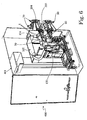
- FIG. 6 illustrates an exemplary embodiment of a switchgear panel 400, which can be also indicated with the equivalent terms of electric switchboard, or simply switchgear or similar definitions; the panel 400 usually comprises a metallic cubicle or cabinet 401 (shown in figure 6 partially cut for the sake of better illustrating the internal parts) that houses various apparatuses and equipment, and in particular a circuit breaker 150.
- a switchgear panel 400 which can be also indicated with the equivalent terms of electric switchboard, or simply switchgear or similar definitions
- the panel 400 usually comprises a metallic cubicle or cabinet 401 (shown in figure 6 partially cut for the sake of better illustrating the internal parts) that houses various apparatuses and equipment, and in particular a circuit breaker 150.
- the circuit breaker 150 comprises a plurality of connection contacts 50, 60; each connection contact 50 (or 60) is suitable to be electrically connected to a corresponding contact piece 70 (or 80) of an associated electrical circuit along a respective connection path formed by one or more conductive pieces suitably shaped, such as for instance the illustrated conductor pieces 201, 202, 203, 204.
- the upper contact pieces 70 are connected to a power source while the lower contact pieces 80 can be connected to a supplied and protected load.
- each shell 100 is inserted with its portion 5 inside a hole 103 of the insulating plate 102, while the side walls 104 of the plate 102 are connected to a structural element, e.g. a metallic plate 105 provided inside the cabinet.
- a structural element e.g. a metallic plate 105 provided inside the cabinet.
- the protruding teeth 106 of the side walls 104 are inserted into recesses of the metallic plate 105.
- the entire insulating assembly results compact and sturdy and for instance a new switchgear panel can be retrofitted with a new, standard and non-modified circuit breaker, even without any particular modification to switchgear panel itself or the insulating device itself.
- the holes 103 in the insulating plate can be defined in the desired position, while the insulating shells 100, thanks to their structure have a certain degree of positioning relative to the plate itself and the associated conductors 200 that they are devised to insulate; in addition, when more shells 100 are used, possible problems of total space available in the cabinet or among the shells 100 themselves can be faced thanks to the possibility, as previously described, of easily adjust the size and therefore the encumbrance of each shell 100.
- any switchgear panel it is always possible, even inside any switchgear panel, to use one or more electrically insulating shells 100 alone, namely without combining them with the insulating plate 102 or any else insulating component; for example, in the switchgear panel 400 the shells 100 can be coupled with the associated conductors as illustrated in figure 6 but without using the plate 102.
- the electrically insulating shell 100, the electrically insulating device 300 and related switchgear panel 400 thus conceived, are susceptible of modifications and variations, all of which are within the scope of the inventive concept including any combination of the above described embodiments which have to be considered as encompassed by the above description; all details may further be replaced with other technically equivalent elements.
- the materials, so long as they are compatible with the specific use, as well as the individual components, may be any according to the requirements and the state of the art.
Landscapes
- Engineering & Computer Science (AREA)
- Power Engineering (AREA)
- Patch Boards (AREA)
- Casings For Electric Apparatus (AREA)
- Switch Cases, Indication, And Locking (AREA)
- Gas-Insulated Switchgears (AREA)
- Distribution Board (AREA)
Claims (13)
- Coque électriquement isolante (100) appropriée pour être associée de manière fonctionnelle à un conducteur électrique (200) comprenant une ou plusieurs pièce(s) reliées ensemble, la coque isolante (100) comprenant une première demi-coque (1) et une deuxième demi-coque (2) conçues pour être mutuellement reliées l'une à l'autre, caractérisée en ce que ladite première demi-coque (1) et ladite deuxième demi-coque (2) sont mises en forme de manière à définir, une fois reliées l'une à l'autre, une partie centrale (3) délimitant un espace essentiellement fermé enfermant dedans une première partie correspondante (201) dudit conducteur électrique (200), une première partie creuse (4) faisant saillie à partir d'un premier côté de ladite partie centrale (3), ladite première partie creuse (4) étant en communication spatiale avec l'espace interne de ladite partie centrale fermée (3) et adaptée pour entourer une deuxième partie correspondante (202) dudit conducteur électrique appropriée pour être reliée à une pièce de contact (70) d'un circuit électrique, et une deuxième partie creuse (5) faisant saillie à partir de ladite partie centrale (3) d'un deuxième côté opposé audit premier côté, ladite deuxième partie creuse (5) étant en communication spatiale avec l'espace interne de ladite partie centrale fermée (3) et adaptée pour entourer une troisième partie correspondante (203) dudit conducteur électrique (200) appropriée pour être reliée à un contact de connexion (50) d'un disjoncteur (150) associé audit circuit électrique, et dans lequel au moins l'une parmi lesdites première demi-coque (1) et deuxième demi-coque (2) comprend un corps ayant une pluralité d'encoches de référence (30) adaptées pour permettre de découper des parties du corps mis en forme lui-même.
- Coque électriquement isolante (100) selon l'une ou plusieurs des revendications précédentes, dans laquelle ladite première demi-coque (1) et ladite deuxième demi-coque (2) comprennent un premier moyen de couplage (6) et un deuxième moyen de couplage (7), respectivement, qui sont appropriés pour s'engager mutuellement de manière à relier mécaniquement ladite première demi-coque (1) et ladite deuxième demi-coque (2) l'une à l'autre par encliquetage.
- Coque électriquement isolante (100) selon l'une ou plusieurs des revendications précédentes, dans laquelle ladite première demi-coque (1) comprend corpsayant une première paroi de base (8), une ou plusieurs première(s) paroi(s) latérale(s) (9) faisant saillie transversalement à partir de ladite première paroi de base (8), ledit premier moyen de couplage (6) comprenant une ou plusieurs dent(s) (6) prévue(s) sur au moins l'une de ladite/desdites une ou plusieurs première(s) paroi(s) latérale(s) (9), et dans laquelle ladite première partie creuse (4) comprend une première partie tubulaire creuse (4) qui est rendue solidaire à ladite première paroi de base (8) et fait saillie perpendiculairement à partir de celle-ci dans une direction opposée à celle de ladite/desdites une ou plusieurs première(s) paroi(s) latérale(s) (9).
- Dispositif électriquement isolant (100) selon la revendication 3, dans lequel ladite première demi-coque (1) comprend une première pluralité d'encoches de référence (30) qui sont prévues au moins le long de ladite première paroi de base (8) et sont adaptées pour permettre de découper des parties de son corps mis en forme de manière à ajuster la longueur de la première demi-coque (1).
- Coque électriquement isolante (100) selon l'une ou plusieurs des revendications précédentes, dans laquelle ladite première demi-coque (1) comprend une première pluralité d'ailettes de centrage (11) prévues sur la surface interne de ladite première partie tubulaire creuse (4).
- Coque électriquement isolante (100) selon l'une ou plusieurs des revendications précédentes, dans laquelle ladite deuxième demi-coque (2) comprend un corps ayant une deuxième paroi de base (12), une ou plusieurs deuxième(s) paroi(s) latérale(s) (13) faisant saillie transversalement à partir de ladite deuxième paroi de base (12), ledit deuxième moyen de couplage (7) comprenant des crochets (7) prévus sur au moins l'une de ladite/desdites une ou plusieurs deuxième(s) paroi(s) latérale(s) (13), et dans laquelle ladite deuxième partie creuse (5) comprend une deuxième partie tubulaire creuse (5) qui est rendue solidaire à ladite deuxième paroi de base (12) et fait saillie perpendiculairement à partir de celle-ci dans une direction opposée à celle de ladite/desdites une ou plusieurs deuxième(s) paroi(s) latérale(s) (13).
- Coque électriquement isolante (100) selon l'une ou plusieurs des revendications précédentes, dans laquelle ladite deuxième partie tubulaire creuse (5) comporte une paroi de fond (14) ayant une partie centrale comprenant un trou principal (15), ladite paroi de fond (14) comprenant une ou plusieurs encoche(s) (31, 32) de manière à permettre de découper ladite partie centrale comprenant ledit trou principal (15).
- Coque électriquement isolante (100) selon l'une ou plusieurs des revendications 7 et 8, dans laquelle ladite deuxième demi-coque (2) comprend une pluralité d'encoches de référence (30) qui sont prévues au moins le long de ladite deuxième paroi de base (12) et sont adaptées pour permettre de découper des parties de son corps mis en forme de manière à ajuster la longueur de la deuxième demi-coque (2).
- Coque électriquement isolante (100) selon l'une ou plusieurs des revendications précédentes, dans laquelle ladite première demi-coque (1) comprend une première barrière isolante (20), une deuxième barrière isolante (21), une troisième barrière isolante (22), et une quatrième barrière isolante (23), qui s'étendent toutes à partir d'un côté de ladite première paroi de base (8) essentiellement en parallèle les unes avec les autres et avec lesdites premières parois latérales (9), lesdites première et deuxième barrières isolantes (20, 21) étant positionnées l'une à proximité de l'autre et de manière espacée l'une de l'autre d'un premier espace (25), lesdites troisième et quatrième barrières isolantes (22, 23) étant positionnées l'une à proximité de l'autre et de manière espacée l'une de l'autre d'un deuxième espace (26), et dans laquelle ladite deuxième demi-coque (2) comprend une cinquième barrière isolante (27) et une sixième barrière isolante (28) qui s'étendent à partir d'un côté de ladite deuxième paroi de base (12) essentiellement en parallèle l'une avec l'autre et avec lesdites deuxièmes parois latérales (13), ladite cinquième barrière isolante (27) et ladite sixième barrière isolante (28) étant adaptées pour entrer dans ledit premier espace (25) et dans ledit deuxième espace (26), respectivement, lorsque lesdites première et deuxième demi-coques (1, 2) sont mutuellement reliées.
- Dispositif électriquement isolant (300), caractérisé en ce qu'il comprend une ou plusieurs coque(s) isolante(s) (100) selon l'une ou plusieurs des revendications précédentes, et une plaque isolante (102) ayant une partie centrale perforée avec un ou plusieurs trou(s) (103) à l'intérieur de chacun desquels la deuxième partie (5) d'une coque isolante correspondante (100) est appropriée pour être insérée.
- Dispositif électriquement isolant (300) selon la revendication 10, dans lequel ladite plaque isolante (102) comprend une ou plusieurs paroi(s) latérale(s) (104) qui fait/font saillie transversalement à partir de ladite partie centrale et est/sont adaptée(s) pour être reliée(s) mécaniquement à un autre composant.
- Panneau d'appareillage de commutation (400) comprenant un coffret (401), un disjoncteur (150) positionné à l'intérieur dudit coffret et approprié pour être électriquement relié en entrée et en sortie à un circuit électrique associé le long de chemins de connexion électriques formés chacun par une ou plusieurs pièce(s) conductrice(s), caractérisé en ce qu'il comprend au moins une coque électriquement isolante (100) selon l'une ou plusieurs des revendications 1 à 9, ladite au moins une coque isolante (100) étant positionnée de manière fonctionnelle le long de l'un desdits chemins conducteurs de manière à isoler électriquement au moins une partie du chemin du milieu environnant.
- Panneau d'appareillage de commutation (400) comprenant un coffret (401), un disjoncteur (150) positionné à l'intérieur dudit coffret et ayant une pluralité de contacts de connexion (50, 60) appropriés pour être reliés électriquement chacun à une pièce de contact correspondante (70, 80) d'un circuit électrique associé le long d'un chemin de connexion respectif formé par une ou plusieurs pièce(s) conductrice(s), caractérisé en ce qu'il comprend un dispositif électriquement isolant (300) selon l'une ou plusieurs des revendications 10 à 11, et dans lequel ladite plaque isolante (102) comprend une ou plusieurs paroi(s) latérale(s) (104) qui fait/font saillie transversalement à partir de ladite partie centrale et est/sont reliée(s) mécaniquement à un autre composant du panneau.
Priority Applications (7)
| Application Number | Priority Date | Filing Date | Title |
|---|---|---|---|
| EP12171309.3A EP2672590B1 (fr) | 2012-06-08 | 2012-06-08 | Coque électriquement isolante, dispositif d'isolation électrique comprenant une telle coque isolante et panneau d'appareillage de commutation associé |
| ES12171309.3T ES2534186T3 (es) | 2012-06-08 | 2012-06-08 | Carcasa de aislamiento eléctrico, dispositivo de aislamiento eléctrico que comprende tal carcasa de aislamiento, y panel de conmutador asociado |
| RU2014152805A RU2630235C1 (ru) | 2012-06-08 | 2013-05-13 | Электрически изолирующая оболочка, электрически изолирующее устройство, содержащее такую изолирующую оболочку, и соответствующая распределительная панель |
| PCT/EP2013/059851 WO2013182380A1 (fr) | 2012-06-08 | 2013-05-13 | Coque électriquement isolante, dispositif électriquement isolant comprenant une telle coque isolante et panneau d'appareillage de commutation apparenté |
| BR112014030705-9A BR112014030705B1 (pt) | 2012-06-08 | 2013-05-13 | Cobertura eletricamente isolante, dispositivo eletricamente isolante compreendendo tal cobertura isolante e painel de comutação relacionado |
| CN201380030146.4A CN104380551B (zh) | 2012-06-08 | 2013-05-13 | 电绝缘壳、电绝缘装置及开关设备面板 |
| US14/560,625 US9559500B2 (en) | 2012-06-08 | 2014-12-04 | Electrically insulating shell, an electrically insulating device comprising such insulating shell, and related switchgear panel |
Applications Claiming Priority (1)
| Application Number | Priority Date | Filing Date | Title |
|---|---|---|---|
| EP12171309.3A EP2672590B1 (fr) | 2012-06-08 | 2012-06-08 | Coque électriquement isolante, dispositif d'isolation électrique comprenant une telle coque isolante et panneau d'appareillage de commutation associé |
Publications (2)
| Publication Number | Publication Date |
|---|---|
| EP2672590A1 EP2672590A1 (fr) | 2013-12-11 |
| EP2672590B1 true EP2672590B1 (fr) | 2015-01-14 |
Family
ID=48463962
Family Applications (1)
| Application Number | Title | Priority Date | Filing Date |
|---|---|---|---|
| EP12171309.3A Active EP2672590B1 (fr) | 2012-06-08 | 2012-06-08 | Coque électriquement isolante, dispositif d'isolation électrique comprenant une telle coque isolante et panneau d'appareillage de commutation associé |
Country Status (7)
| Country | Link |
|---|---|
| US (1) | US9559500B2 (fr) |
| EP (1) | EP2672590B1 (fr) |
| CN (1) | CN104380551B (fr) |
| BR (1) | BR112014030705B1 (fr) |
| ES (1) | ES2534186T3 (fr) |
| RU (1) | RU2630235C1 (fr) |
| WO (1) | WO2013182380A1 (fr) |
Families Citing this family (7)
| Publication number | Priority date | Publication date | Assignee | Title |
|---|---|---|---|---|
| EP3032665B1 (fr) * | 2014-12-09 | 2019-09-11 | ABB Schweiz AG | Dispositif de rattrapage pour appareillage de commutation moyenne tension |
| HRP20221312T1 (hr) * | 2015-03-31 | 2023-03-17 | General Electric Technology Gmbh | Gornje kućište |
| CN107275942B (zh) * | 2017-08-18 | 2023-04-07 | 国网黑龙江省电力有限公司鹤岗供电公司 | 可调节便携绝缘固定隔板及其安装方法 |
| RU2703215C1 (ru) * | 2018-05-31 | 2019-10-15 | Алексей Павлович Пищур | Комплекс адаптационного оборудования кад-0.4 |
| RU2710918C2 (ru) * | 2018-07-09 | 2020-01-14 | Алексей Павлович Пищур | Комплекс адаптационного оборудования кад-10 |
| RU2766310C2 (ru) * | 2019-12-23 | 2022-03-15 | Алексей Павлович Пищур | Комплекс адаптационного оборудования кад-6 |
| CN113394684B (zh) * | 2021-06-21 | 2023-05-16 | 湖南湖电电力设备有限公司 | 一种电力配网自动化控制箱 |
Family Cites Families (22)
| Publication number | Priority date | Publication date | Assignee | Title |
|---|---|---|---|---|
| USRE23811E (en) * | 1954-03-30 | Bus bab housing | ||
| US1797936A (en) | 1929-01-05 | 1931-03-24 | Gen Electric | Electric switching apparatus |
| US2469445A (en) * | 1944-03-25 | 1949-05-10 | Ite Circuit Breaker Ltd | Bus bar housing |
| US2875265A (en) * | 1954-12-30 | 1959-02-24 | Ite Circuit Breaker Ltd | Metal enclosed isolated phase bus structure |
| US3020329A (en) * | 1957-11-22 | 1962-02-06 | Ite Circuit Breaker Ltd | Housing for bus run |
| US3662137A (en) | 1970-01-21 | 1972-05-09 | Westinghouse Electric Corp | Switchgear having heat pipes incorporated in the disconnecting structures and power conductors |
| DE2301460C3 (de) * | 1973-01-12 | 1980-07-03 | Siemens Ag, 1000 Berlin Und 8000 Muenchen | Steigleitungsschienensystem |
| DE3328785A1 (de) * | 1983-08-10 | 1985-02-28 | Brown, Boveri & Cie Ag, 6800 Mannheim | Durchfuehrungsisolator fuer eine schottwandung in einem anlagenschrank fuer mittelspannungsschalt- und -verteileranlagen |
| FR2569061B1 (fr) * | 1984-08-07 | 1987-01-02 | Alsthom Atlantique | Dispositif de distribution electrique a basse tension |
| US4818822A (en) * | 1987-11-04 | 1989-04-04 | Yahraus Norman J | Junction box |
| IT1292340B1 (it) * | 1997-05-20 | 1999-01-29 | Gewiss Spa | Gruppo modulare per cablaggio veloce per quadri elettrici e simili |
| RU2161849C1 (ru) * | 1999-05-11 | 2001-01-10 | ФГУП "Конструкторское бюро транспортного машиностроения" | Коммутационное устройство |
| US7724146B2 (en) * | 2004-11-17 | 2010-05-25 | Sensormatic Electronics, LLC | Magnetically releasable electronic article surveillance tag |
| CN2935509Y (zh) * | 2006-08-03 | 2007-08-15 | 温州大观电气有限公司 | 电缆连接绝缘装置 |
| FR2903241A1 (fr) * | 2006-11-23 | 2008-01-04 | Areva T & D Sa | Enveloppe d'appareillage electrique haute ou moyenne tension constituee de deux demi-coquilles assemblees par soudage thermique |
| PL1962397T3 (pl) | 2007-02-23 | 2013-06-28 | Gen Electric | Układ blokowania żaluzji dla wyjmowanych wyłączników instalacyjnych oraz sposób jego montażu |
| FR2934427B1 (fr) * | 2008-07-22 | 2010-09-03 | Inovac | Couvercle encliquetable de goulotte, et goulotte munie d'un tel couvercle encliquetable |
| WO2011037786A1 (fr) * | 2009-09-24 | 2011-03-31 | Abb Technology Ag | Ensemble de traversées pour sectionneurs de circuit amovibles |
| CN102754293B (zh) | 2009-11-23 | 2015-04-01 | Abb技术有限公司 | 用于改装断路器的方法和系统 |
| EP2405545B8 (fr) | 2010-07-07 | 2017-01-25 | ABB Schweiz AG | Dispositif obturateur et appareil de commutation utilisant ce dispositif obturateur |
| ES2657836T3 (es) * | 2012-06-08 | 2018-03-07 | Abb Schweiz Ag | Adaptador eléctrico y panel de conmutación asociado |
| DE102012110262B4 (de) * | 2012-10-26 | 2017-02-09 | Ditter Plastic Gmbh + Co. Kg | Spritzkörper und Verfahren zu seiner Herstellung |
-
2012
- 2012-06-08 EP EP12171309.3A patent/EP2672590B1/fr active Active
- 2012-06-08 ES ES12171309.3T patent/ES2534186T3/es active Active
-
2013
- 2013-05-13 CN CN201380030146.4A patent/CN104380551B/zh active Active
- 2013-05-13 WO PCT/EP2013/059851 patent/WO2013182380A1/fr not_active Ceased
- 2013-05-13 BR BR112014030705-9A patent/BR112014030705B1/pt active IP Right Grant
- 2013-05-13 RU RU2014152805A patent/RU2630235C1/ru active
-
2014
- 2014-12-04 US US14/560,625 patent/US9559500B2/en active Active
Also Published As
| Publication number | Publication date |
|---|---|
| ES2534186T3 (es) | 2015-04-20 |
| RU2630235C1 (ru) | 2017-09-06 |
| US20150171603A1 (en) | 2015-06-18 |
| EP2672590A1 (fr) | 2013-12-11 |
| CN104380551A (zh) | 2015-02-25 |
| BR112014030705A8 (pt) | 2017-12-26 |
| BR112014030705A2 (pt) | 2017-08-08 |
| US9559500B2 (en) | 2017-01-31 |
| CN104380551B (zh) | 2017-05-31 |
| WO2013182380A1 (fr) | 2013-12-12 |
| BR112014030705B1 (pt) | 2021-04-06 |
Similar Documents
| Publication | Publication Date | Title |
|---|---|---|
| EP2672590B1 (fr) | Coque électriquement isolante, dispositif d'isolation électrique comprenant une telle coque isolante et panneau d'appareillage de commutation associé | |
| JP6120983B2 (ja) | 変流器支持装置及びその変流器支持装置を用いたスイッチギヤ | |
| EP3667844B1 (fr) | Conducteur pour un système de distribution d'énergie | |
| CN104637741A (zh) | 塑壳断路器 | |
| US20100254074A1 (en) | Electrical enclosures having configurable panel layouts | |
| CN201556721U (zh) | 接线端子和具有接线端子的电气安装设备 | |
| BR102015007221A2 (pt) | dispositivo para medir pelo menos uma variável elétrica de uma corrente destinada a fluir em um aparelho elétrico e conjunto compreendendo tal dispositivo | |
| US9728922B2 (en) | Electrical adapter, and related switchgear panel | |
| CN103682998A (zh) | 用于汇流排支撑的模块化绝缘体及装配方法 | |
| EA029142B1 (ru) | Предварительно изготовленная адаптируемая слоистая система сборных шин и способ адаптации длины указанной системы сборных шин | |
| EP3163694B1 (fr) | Couvercle solant pour ensemble de bornes | |
| KR200450125Y1 (ko) | 차단기 직결형 영상변류기 | |
| US9263860B2 (en) | Power distribution system, and switchgear assembly, and mounting member therefor | |
| KR101236917B1 (ko) | 조립식 컴팩트형 표준 분전반 | |
| KR200431266Y1 (ko) | 배전반의 모선부스바 | |
| JP7488970B2 (ja) | 回路遮断器 | |
| CN112736601A (zh) | 用于配电系统的导体组件 | |
| KR101582610B1 (ko) | 배전반 버킷의 2차측 커넥터용 메일 커넥터 | |
| WO2017081656A1 (fr) | Support arrière de distribution modulaire pour disjoncteurs | |
| KR200475784Y1 (ko) | 시티 개방방지용 단자대 | |
| CN104170045A (zh) | 电力用开关装置 | |
| CN105580228A (zh) | 用于将导电条安装在配电板机柜中的组件 | |
| PL66095Y1 (pl) | Listwa zaciskowa | |
| BR102014005847A2 (pt) | barramento para conexão de disjuntores |
Legal Events
| Date | Code | Title | Description |
|---|---|---|---|
| PUAI | Public reference made under article 153(3) epc to a published international application that has entered the european phase |
Free format text: ORIGINAL CODE: 0009012 |
|
| AK | Designated contracting states |
Kind code of ref document: A1 Designated state(s): AL AT BE BG CH CY CZ DE DK EE ES FI FR GB GR HR HU IE IS IT LI LT LU LV MC MK MT NL NO PL PT RO RS SE SI SK SM TR |
|
| AX | Request for extension of the european patent |
Extension state: BA ME |
|
| 17P | Request for examination filed |
Effective date: 20140523 |
|
| RBV | Designated contracting states (corrected) |
Designated state(s): AL AT BE BG CH CY CZ DE DK EE ES FI FR GB GR HR HU IE IS IT LI LT LU LV MC MK MT NL NO PL PT RO RS SE SI SK SM TR |
|
| GRAP | Despatch of communication of intention to grant a patent |
Free format text: ORIGINAL CODE: EPIDOSNIGR1 |
|
| INTG | Intention to grant announced |
Effective date: 20140903 |
|
| GRAS | Grant fee paid |
Free format text: ORIGINAL CODE: EPIDOSNIGR3 |
|
| GRAA | (expected) grant |
Free format text: ORIGINAL CODE: 0009210 |
|
| AK | Designated contracting states |
Kind code of ref document: B1 Designated state(s): AL AT BE BG CH CY CZ DE DK EE ES FI FR GB GR HR HU IE IS IT LI LT LU LV MC MK MT NL NO PL PT RO RS SE SI SK SM TR |
|
| REG | Reference to a national code |
Ref country code: GB Ref legal event code: FG4D |
|
| REG | Reference to a national code |
Ref country code: CH Ref legal event code: EP |
|
| REG | Reference to a national code |
Ref country code: IE Ref legal event code: FG4D |
|
| REG | Reference to a national code |
Ref country code: AT Ref legal event code: REF Ref document number: 707465 Country of ref document: AT Kind code of ref document: T Effective date: 20150215 |
|
| REG | Reference to a national code |
Ref country code: DE Ref legal event code: R096 Ref document number: 602012004878 Country of ref document: DE Effective date: 20150226 |
|
| REG | Reference to a national code |
Ref country code: ES Ref legal event code: FG2A Ref document number: 2534186 Country of ref document: ES Kind code of ref document: T3 Effective date: 20150420 |
|
| REG | Reference to a national code |
Ref country code: NL Ref legal event code: VDEP Effective date: 20150114 |
|
| REG | Reference to a national code |
Ref country code: AT Ref legal event code: MK05 Ref document number: 707465 Country of ref document: AT Kind code of ref document: T Effective date: 20150114 |
|
| REG | Reference to a national code |
Ref country code: LT Ref legal event code: MG4D |
|
| PG25 | Lapsed in a contracting state [announced via postgrant information from national office to epo] |
Ref country code: LT Free format text: LAPSE BECAUSE OF FAILURE TO SUBMIT A TRANSLATION OF THE DESCRIPTION OR TO PAY THE FEE WITHIN THE PRESCRIBED TIME-LIMIT Effective date: 20150114 Ref country code: NO Free format text: LAPSE BECAUSE OF FAILURE TO SUBMIT A TRANSLATION OF THE DESCRIPTION OR TO PAY THE FEE WITHIN THE PRESCRIBED TIME-LIMIT Effective date: 20150414 Ref country code: BG Free format text: LAPSE BECAUSE OF FAILURE TO SUBMIT A TRANSLATION OF THE DESCRIPTION OR TO PAY THE FEE WITHIN THE PRESCRIBED TIME-LIMIT Effective date: 20150414 Ref country code: SE Free format text: LAPSE BECAUSE OF FAILURE TO SUBMIT A TRANSLATION OF THE DESCRIPTION OR TO PAY THE FEE WITHIN THE PRESCRIBED TIME-LIMIT Effective date: 20150114 Ref country code: HR Free format text: LAPSE BECAUSE OF FAILURE TO SUBMIT A TRANSLATION OF THE DESCRIPTION OR TO PAY THE FEE WITHIN THE PRESCRIBED TIME-LIMIT Effective date: 20150114 Ref country code: FI Free format text: LAPSE BECAUSE OF FAILURE TO SUBMIT A TRANSLATION OF THE DESCRIPTION OR TO PAY THE FEE WITHIN THE PRESCRIBED TIME-LIMIT Effective date: 20150114 |
|
| PG25 | Lapsed in a contracting state [announced via postgrant information from national office to epo] |
Ref country code: IS Free format text: LAPSE BECAUSE OF FAILURE TO SUBMIT A TRANSLATION OF THE DESCRIPTION OR TO PAY THE FEE WITHIN THE PRESCRIBED TIME-LIMIT Effective date: 20150514 Ref country code: PL Free format text: LAPSE BECAUSE OF FAILURE TO SUBMIT A TRANSLATION OF THE DESCRIPTION OR TO PAY THE FEE WITHIN THE PRESCRIBED TIME-LIMIT Effective date: 20150114 Ref country code: GR Free format text: LAPSE BECAUSE OF FAILURE TO SUBMIT A TRANSLATION OF THE DESCRIPTION OR TO PAY THE FEE WITHIN THE PRESCRIBED TIME-LIMIT Effective date: 20150415 Ref country code: AT Free format text: LAPSE BECAUSE OF FAILURE TO SUBMIT A TRANSLATION OF THE DESCRIPTION OR TO PAY THE FEE WITHIN THE PRESCRIBED TIME-LIMIT Effective date: 20150114 Ref country code: LV Free format text: LAPSE BECAUSE OF FAILURE TO SUBMIT A TRANSLATION OF THE DESCRIPTION OR TO PAY THE FEE WITHIN THE PRESCRIBED TIME-LIMIT Effective date: 20150114 Ref country code: RS Free format text: LAPSE BECAUSE OF FAILURE TO SUBMIT A TRANSLATION OF THE DESCRIPTION OR TO PAY THE FEE WITHIN THE PRESCRIBED TIME-LIMIT Effective date: 20150114 Ref country code: NL Free format text: LAPSE BECAUSE OF FAILURE TO SUBMIT A TRANSLATION OF THE DESCRIPTION OR TO PAY THE FEE WITHIN THE PRESCRIBED TIME-LIMIT Effective date: 20150114 |
|
| REG | Reference to a national code |
Ref country code: DE Ref legal event code: R097 Ref document number: 602012004878 Country of ref document: DE |
|
| PG25 | Lapsed in a contracting state [announced via postgrant information from national office to epo] |
Ref country code: SK Free format text: LAPSE BECAUSE OF FAILURE TO SUBMIT A TRANSLATION OF THE DESCRIPTION OR TO PAY THE FEE WITHIN THE PRESCRIBED TIME-LIMIT Effective date: 20150114 Ref country code: DK Free format text: LAPSE BECAUSE OF FAILURE TO SUBMIT A TRANSLATION OF THE DESCRIPTION OR TO PAY THE FEE WITHIN THE PRESCRIBED TIME-LIMIT Effective date: 20150114 Ref country code: CZ Free format text: LAPSE BECAUSE OF FAILURE TO SUBMIT A TRANSLATION OF THE DESCRIPTION OR TO PAY THE FEE WITHIN THE PRESCRIBED TIME-LIMIT Effective date: 20150114 Ref country code: EE Free format text: LAPSE BECAUSE OF FAILURE TO SUBMIT A TRANSLATION OF THE DESCRIPTION OR TO PAY THE FEE WITHIN THE PRESCRIBED TIME-LIMIT Effective date: 20150114 Ref country code: RO Free format text: LAPSE BECAUSE OF FAILURE TO SUBMIT A TRANSLATION OF THE DESCRIPTION OR TO PAY THE FEE WITHIN THE PRESCRIBED TIME-LIMIT Effective date: 20150114 |
|
| PLBE | No opposition filed within time limit |
Free format text: ORIGINAL CODE: 0009261 |
|
| STAA | Information on the status of an ep patent application or granted ep patent |
Free format text: STATUS: NO OPPOSITION FILED WITHIN TIME LIMIT |
|
| 26N | No opposition filed |
Effective date: 20151015 |
|
| PG25 | Lapsed in a contracting state [announced via postgrant information from national office to epo] |
Ref country code: MC Free format text: LAPSE BECAUSE OF FAILURE TO SUBMIT A TRANSLATION OF THE DESCRIPTION OR TO PAY THE FEE WITHIN THE PRESCRIBED TIME-LIMIT Effective date: 20150114 |
|
| REG | Reference to a national code |
Ref country code: CH Ref legal event code: PL |
|
| PG25 | Lapsed in a contracting state [announced via postgrant information from national office to epo] |
Ref country code: LU Free format text: LAPSE BECAUSE OF FAILURE TO SUBMIT A TRANSLATION OF THE DESCRIPTION OR TO PAY THE FEE WITHIN THE PRESCRIBED TIME-LIMIT Effective date: 20150608 Ref country code: SI Free format text: LAPSE BECAUSE OF FAILURE TO SUBMIT A TRANSLATION OF THE DESCRIPTION OR TO PAY THE FEE WITHIN THE PRESCRIBED TIME-LIMIT Effective date: 20150114 |
|
| REG | Reference to a national code |
Ref country code: IE Ref legal event code: MM4A |
|
| PG25 | Lapsed in a contracting state [announced via postgrant information from national office to epo] |
Ref country code: IE Free format text: LAPSE BECAUSE OF NON-PAYMENT OF DUE FEES Effective date: 20150608 Ref country code: CH Free format text: LAPSE BECAUSE OF NON-PAYMENT OF DUE FEES Effective date: 20150630 Ref country code: LI Free format text: LAPSE BECAUSE OF NON-PAYMENT OF DUE FEES Effective date: 20150630 |
|
| PG25 | Lapsed in a contracting state [announced via postgrant information from national office to epo] |
Ref country code: BE Free format text: LAPSE BECAUSE OF FAILURE TO SUBMIT A TRANSLATION OF THE DESCRIPTION OR TO PAY THE FEE WITHIN THE PRESCRIBED TIME-LIMIT Effective date: 20150114 |
|
| REG | Reference to a national code |
Ref country code: FR Ref legal event code: PLFP Year of fee payment: 5 |
|
| PG25 | Lapsed in a contracting state [announced via postgrant information from national office to epo] |
Ref country code: MT Free format text: LAPSE BECAUSE OF FAILURE TO SUBMIT A TRANSLATION OF THE DESCRIPTION OR TO PAY THE FEE WITHIN THE PRESCRIBED TIME-LIMIT Effective date: 20150114 |
|
| REG | Reference to a national code |
Ref country code: DE Ref legal event code: R082 Ref document number: 602012004878 Country of ref document: DE Representative=s name: KUHNEN & WACKER PATENT- UND RECHTSANWALTSBUERO, DE Ref country code: DE Ref legal event code: R081 Ref document number: 602012004878 Country of ref document: DE Owner name: ABB SCHWEIZ AG, CH Free format text: FORMER OWNER: ABB TECHNOLOGY AG, ZUERICH, CH |
|
| PG25 | Lapsed in a contracting state [announced via postgrant information from national office to epo] |
Ref country code: SM Free format text: LAPSE BECAUSE OF FAILURE TO SUBMIT A TRANSLATION OF THE DESCRIPTION OR TO PAY THE FEE WITHIN THE PRESCRIBED TIME-LIMIT Effective date: 20150114 Ref country code: HU Free format text: LAPSE BECAUSE OF FAILURE TO SUBMIT A TRANSLATION OF THE DESCRIPTION OR TO PAY THE FEE WITHIN THE PRESCRIBED TIME-LIMIT; INVALID AB INITIO Effective date: 20120608 |
|
| REG | Reference to a national code |
Ref country code: FR Ref legal event code: PLFP Year of fee payment: 6 |
|
| PG25 | Lapsed in a contracting state [announced via postgrant information from national office to epo] |
Ref country code: CY Free format text: LAPSE BECAUSE OF FAILURE TO SUBMIT A TRANSLATION OF THE DESCRIPTION OR TO PAY THE FEE WITHIN THE PRESCRIBED TIME-LIMIT Effective date: 20150114 |
|
| PG25 | Lapsed in a contracting state [announced via postgrant information from national office to epo] |
Ref country code: TR Free format text: LAPSE BECAUSE OF FAILURE TO SUBMIT A TRANSLATION OF THE DESCRIPTION OR TO PAY THE FEE WITHIN THE PRESCRIBED TIME-LIMIT Effective date: 20150114 |
|
| REG | Reference to a national code |
Ref country code: ES Ref legal event code: PC2A Owner name: ABB SCHWEIZ AG Effective date: 20171213 |
|
| REG | Reference to a national code |
Ref country code: GB Ref legal event code: 732E Free format text: REGISTERED BETWEEN 20180426 AND 20180502 |
|
| REG | Reference to a national code |
Ref country code: FR Ref legal event code: PLFP Year of fee payment: 7 |
|
| PG25 | Lapsed in a contracting state [announced via postgrant information from national office to epo] |
Ref country code: MK Free format text: LAPSE BECAUSE OF FAILURE TO SUBMIT A TRANSLATION OF THE DESCRIPTION OR TO PAY THE FEE WITHIN THE PRESCRIBED TIME-LIMIT Effective date: 20150114 Ref country code: PT Free format text: LAPSE BECAUSE OF FAILURE TO SUBMIT A TRANSLATION OF THE DESCRIPTION OR TO PAY THE FEE WITHIN THE PRESCRIBED TIME-LIMIT Effective date: 20150114 |
|
| REG | Reference to a national code |
Ref country code: FR Ref legal event code: TP Owner name: ABB SCHWEIZ AG, CH Effective date: 20180912 |
|
| PG25 | Lapsed in a contracting state [announced via postgrant information from national office to epo] |
Ref country code: AL Free format text: LAPSE BECAUSE OF FAILURE TO SUBMIT A TRANSLATION OF THE DESCRIPTION OR TO PAY THE FEE WITHIN THE PRESCRIBED TIME-LIMIT Effective date: 20150114 |
|
| PGFP | Annual fee paid to national office [announced via postgrant information from national office to epo] |
Ref country code: DE Payment date: 20250618 Year of fee payment: 14 |
|
| PGFP | Annual fee paid to national office [announced via postgrant information from national office to epo] |
Ref country code: GB Payment date: 20250618 Year of fee payment: 14 |
|
| PGFP | Annual fee paid to national office [announced via postgrant information from national office to epo] |
Ref country code: FR Payment date: 20250624 Year of fee payment: 14 |
|
| PGFP | Annual fee paid to national office [announced via postgrant information from national office to epo] |
Ref country code: ES Payment date: 20250728 Year of fee payment: 14 |
|
| PGFP | Annual fee paid to national office [announced via postgrant information from national office to epo] |
Ref country code: IT Payment date: 20250624 Year of fee payment: 14 |