EP2672638B1 - Procédés et appareil pour pré et post égalisation dans des systèmes de communications optiques - Google Patents
Procédés et appareil pour pré et post égalisation dans des systèmes de communications optiques Download PDFInfo
- Publication number
- EP2672638B1 EP2672638B1 EP13275135.5A EP13275135A EP2672638B1 EP 2672638 B1 EP2672638 B1 EP 2672638B1 EP 13275135 A EP13275135 A EP 13275135A EP 2672638 B1 EP2672638 B1 EP 2672638B1
- Authority
- EP
- European Patent Office
- Prior art keywords
- optical
- modulation format
- test signal
- reception report
- wss
- Prior art date
- Legal status (The legal status is an assumption and is not a legal conclusion. Google has not performed a legal analysis and makes no representation as to the accuracy of the status listed.)
- Not-in-force
Links
- 230000003287 optical effect Effects 0.000 title claims description 107
- 238000004891 communication Methods 0.000 title claims description 38
- 238000000034 method Methods 0.000 title claims description 37
- 230000005540 biological transmission Effects 0.000 claims description 38
- 238000012360 testing method Methods 0.000 claims description 20
- 230000006870 function Effects 0.000 claims description 16
- 230000010287 polarization Effects 0.000 claims description 12
- 238000012546 transfer Methods 0.000 claims description 12
- 230000010363 phase shift Effects 0.000 claims description 3
- 238000001228 spectrum Methods 0.000 description 13
- 230000006735 deficit Effects 0.000 description 12
- 239000000835 fiber Substances 0.000 description 10
- 238000004590 computer program Methods 0.000 description 9
- 238000001914 filtration Methods 0.000 description 9
- 238000001514 detection method Methods 0.000 description 8
- 230000003321 amplification Effects 0.000 description 7
- 230000000694 effects Effects 0.000 description 7
- 238000003199 nucleic acid amplification method Methods 0.000 description 7
- 230000003595 spectral effect Effects 0.000 description 7
- 230000001427 coherent effect Effects 0.000 description 6
- 238000010586 diagram Methods 0.000 description 6
- 238000007493 shaping process Methods 0.000 description 6
- 238000002474 experimental method Methods 0.000 description 5
- 230000008569 process Effects 0.000 description 5
- 238000011084 recovery Methods 0.000 description 5
- 230000008901 benefit Effects 0.000 description 4
- 238000012545 processing Methods 0.000 description 4
- 238000004422 calculation algorithm Methods 0.000 description 3
- 238000012937 correction Methods 0.000 description 3
- 239000006185 dispersion Substances 0.000 description 3
- 238000005516 engineering process Methods 0.000 description 3
- 230000006872 improvement Effects 0.000 description 3
- 230000003044 adaptive effect Effects 0.000 description 2
- 230000000644 propagated effect Effects 0.000 description 2
- 230000004044 response Effects 0.000 description 2
- 238000013515 script Methods 0.000 description 2
- 230000001629 suppression Effects 0.000 description 2
- 239000000969 carrier Substances 0.000 description 1
- 238000006243 chemical reaction Methods 0.000 description 1
- 230000004087 circulation Effects 0.000 description 1
- 238000007796 conventional method Methods 0.000 description 1
- 238000001378 electrochemiluminescence detection Methods 0.000 description 1
- 230000007274 generation of a signal involved in cell-cell signaling Effects 0.000 description 1
- 238000003780 insertion Methods 0.000 description 1
- 230000037431 insertion Effects 0.000 description 1
- 238000000120 microwave digestion Methods 0.000 description 1
- 239000000203 mixture Substances 0.000 description 1
- 238000012986 modification Methods 0.000 description 1
- 230000004048 modification Effects 0.000 description 1
- 230000009022 nonlinear effect Effects 0.000 description 1
- 230000003134 recirculating effect Effects 0.000 description 1
- 230000001105 regulatory effect Effects 0.000 description 1
- 238000005070 sampling Methods 0.000 description 1
- 239000004065 semiconductor Substances 0.000 description 1
- 238000004088 simulation Methods 0.000 description 1
- 239000000758 substrate Substances 0.000 description 1
- 230000002459 sustained effect Effects 0.000 description 1
Images




Classifications
-
- H—ELECTRICITY
- H04—ELECTRIC COMMUNICATION TECHNIQUE
- H04B—TRANSMISSION
- H04B10/00—Transmission systems employing electromagnetic waves other than radio-waves, e.g. infrared, visible or ultraviolet light, or employing corpuscular radiation, e.g. quantum communication
- H04B10/07—Arrangements for monitoring or testing transmission systems; Arrangements for fault measurement of transmission systems
- H04B10/075—Arrangements for monitoring or testing transmission systems; Arrangements for fault measurement of transmission systems using an in-service signal
- H04B10/077—Arrangements for monitoring or testing transmission systems; Arrangements for fault measurement of transmission systems using an in-service signal using a supervisory or additional signal
- H04B10/0775—Performance monitoring and measurement of transmission parameters
-
- H—ELECTRICITY
- H04—ELECTRIC COMMUNICATION TECHNIQUE
- H04B—TRANSMISSION
- H04B10/00—Transmission systems employing electromagnetic waves other than radio-waves, e.g. infrared, visible or ultraviolet light, or employing corpuscular radiation, e.g. quantum communication
- H04B10/07—Arrangements for monitoring or testing transmission systems; Arrangements for fault measurement of transmission systems
- H04B10/073—Arrangements for monitoring or testing transmission systems; Arrangements for fault measurement of transmission systems using an out-of-service signal
-
- H—ELECTRICITY
- H04—ELECTRIC COMMUNICATION TECHNIQUE
- H04B—TRANSMISSION
- H04B10/00—Transmission systems employing electromagnetic waves other than radio-waves, e.g. infrared, visible or ultraviolet light, or employing corpuscular radiation, e.g. quantum communication
- H04B10/25—Arrangements specific to fibre transmission
- H04B10/2507—Arrangements specific to fibre transmission for the reduction or elimination of distortion or dispersion
-
- H—ELECTRICITY
- H04—ELECTRIC COMMUNICATION TECHNIQUE
- H04B—TRANSMISSION
- H04B10/00—Transmission systems employing electromagnetic waves other than radio-waves, e.g. infrared, visible or ultraviolet light, or employing corpuscular radiation, e.g. quantum communication
- H04B10/50—Transmitters
- H04B10/501—Structural aspects
- H04B10/503—Laser transmitters
- H04B10/505—Laser transmitters using external modulation
- H04B10/5053—Laser transmitters using external modulation using a parallel, i.e. shunt, combination of modulators
-
- H—ELECTRICITY
- H04—ELECTRIC COMMUNICATION TECHNIQUE
- H04B—TRANSMISSION
- H04B10/00—Transmission systems employing electromagnetic waves other than radio-waves, e.g. infrared, visible or ultraviolet light, or employing corpuscular radiation, e.g. quantum communication
- H04B10/50—Transmitters
- H04B10/501—Structural aspects
- H04B10/506—Multiwavelength transmitters
-
- H—ELECTRICITY
- H04—ELECTRIC COMMUNICATION TECHNIQUE
- H04B—TRANSMISSION
- H04B10/00—Transmission systems employing electromagnetic waves other than radio-waves, e.g. infrared, visible or ultraviolet light, or employing corpuscular radiation, e.g. quantum communication
- H04B10/50—Transmitters
- H04B10/516—Details of coding or modulation
- H04B10/54—Intensity modulation
- H04B10/541—Digital intensity or amplitude modulation
-
- H—ELECTRICITY
- H04—ELECTRIC COMMUNICATION TECHNIQUE
- H04B—TRANSMISSION
- H04B2210/00—Indexing scheme relating to optical transmission systems
- H04B2210/25—Distortion or dispersion compensation
- H04B2210/254—Distortion or dispersion compensation before the transmission line, i.e. pre-compensation
Definitions
- This document relates to optical communication systems.
- This document describes technologies, among other things, that may be used to implement optical transmitters and receivers that perform pre-equalization and post-equalization for increased sustained bandwidth throughput in optical communication systems.
- the Nyquist wavelength-division multiplexing technique enable a solution to achieve high spectral efficiency in long-haul transmission system. Compare to polarization division multiplexing quadrature-phase-shift-keying, even high-level modulation scheme such as polarization division multiplexing, 16-quadrature-amplitude-modulation is much more sensitive to intra-channel noise and inter-channel linear crosstalk caused by Nyquist wavelength-division multiplexing.
- a Nyquist-band refers to frequencies between DC and 1 ⁇ 2 of the sampling rate of a digital signal. Nyquist-band is considered in the pre- equalization to enhance the tolerance of the polarization-division multiplexing 16-quadrature-amplitude-modulation to the aggressive spectral shaping.
- the bit error rate for each of the 6 channels is smaller than the limitation of the forward-error-correction limit of 3.8 ⁇ 10-3 after 1200-km SMF-28 transmission.
- a test signal is transmitted over an optical communication medium using a first optical modulation format.
- a reception report that is based on the test signal is received.
- a pre-equalization scheme is determined.
- the pre-equalization scheme is applied to data to be transmitted at a transmitter-side to generate pre-equalized data.
- the pre-equalized data is transmitted over the optical communication medium using a second optical modulation format that is based on the reception report.
- a pre-equalization technique is disclosed that can be used to pre-equalize an optical signal at the transmitter-side.
- One advantageous aspect of the pre-equalization is to partially overcome distortions due to the transfer function of the optical communications channel.
- the first scheme adopts the technique of coherent optical orthogonal-frequency-division-multiplexing (CO-OFDM), it has also been reported that a 485-Gb/s CO-OFDM superchannel with the modulation format of PDM-16QAM experimentally realized the transmission over 1600-km ultra-large-area fiber (ULAF) and standard single-mode-fiber (SSMF)-Based Links.
- the second possible scheme is the Nyquist wavelength-division multiplexing (N-WDM) technique, which is based on the use of optical pulses having an "almost" rectangular spectrum with the bandwidth ideally equal to the baud-rate.
- N-WDM PDM-16QAM signal with a rather high SE.
- CO-OFDM requires synchronization between the channels and much larger receiver bandwidth of the analog-to-digital converters (ADC). Therefore N-WDM is much more robust to the receiver constraints in practical implementation.
- ADC analog-to-digital converters
- the linear distortion due to fiber chromatic dispersion (CD) in the optical domain is converted into a nonlinear distortion in the electrical domain. Therefore, adopting a linear baseband equalizer based on only one baseband received signal can achieve only a limited performance improvements.
- the distortion due to coherent detection (CD) is converted linearly into the electrical domain. This may explain, in the case of considering CD only, why fractionally spaced equalizers with "complex coefficients" can potentially extend the system reach to distances that are only limited by the number of equalizer taps.
- the large constellation size of PDM-16QAM also makes system sensitive to transmitter impairments, e.g.., the nonlinear drive characteristic of the optical modulator and the imbalance between the frequency responses of the in-phase (I) and quadrature (Q) channels), and therefore causes signal distortion and deteriorates the system performance.
- transmitter impairments e.g.., the nonlinear drive characteristic of the optical modulator and the imbalance between the frequency responses of the in-phase (I) and quadrature (Q) channels
- the above-mentioned transmitter impairments in the transmission of PDM-16QAM can be pre-compensated with the technique of pre-equalization, which is quite easy to implement in the digital-analog-converter (DAC) at the transmitter.
- DAC digital-analog-converter
- the modulation format of PDM-16QAM to generate 16-Gbaud signal in N-WDM channel on a 16-GHz grid.
- the present document describes the principle of pre-equalization, and then shows the comparison of bit error rate (BER) performance for the single-channel and N-WDM case with and without Nyquist-band pre-equalization.
- BER bit error rate
- the adoption of pre-equalization can effectively pre-compensate transmitter impairments as well as reduce the effect of nonlinear propagation impairments and laser phase noise.
- the improved BER performance of the N-WDM implementing Nyquist-band pre-equalization shows its tolerance to narrow band filtering effect and crosstalk caused by adjacent channels.
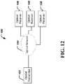
- FIG. 12 is a block diagram representation of an optical communication system 100 where the subject technology disclosed of this document can be implemented.
- An optical transmitter 102 transmits optical signals through an optical network 104 to one or more optical transceivers 106.
- the transmitted optical signals may go through intermediate optical equipment such as amplifiers, repeaters, switch, etc., which are not shown in FIG. 12 for clarity.
- the disclosed transmission techniques can be implemented in the transmission subsystem of the transmitter 102.
- the disclosed reception techniques can be implemented in the receiver subsystem of the receiver 106.
- a pre-equalization is implemented at the transmitter.
- BPSK binary-phase-shift-keying
- the high-constellation level signal suffers much more uncontrolled nonlinear effects due to the imperfection of the Digital to Analog Conversion (DAC), electrical amplifier (EA), in-phase/quadrature modulator (I/Q MOD), optical filter and ADC. Therefore, in some embodiments, a BPSK signal is first transmitted over the transmitter-receiver-only link to calculate the transfer function, which is then used to pre-equalize the high-level signal to reverse the channel distortion.
- DAC Digital to Analog Conversion
- EA electrical amplifier
- I/Q MOD in-phase/quadrature modulator
- FIG. 1 depicts an example of pre-equalization.
- MZMs Mach Zander Modulators
- I/Q MOD is driven using a 16-Gbaud binary signal to generate optical BPSK. While the binary signal with 1.5 ⁇ samples and a word length of 2 15 -1 is generated by arbitrary waveform generator (AWG).
- AWG arbitrary waveform generator
- the electrical low pass filter (LPF) with 3-dB bandwidth of 7.5 GHz is adopted to suppress out-of-band noise of AWG before BPSK signal generation.
- the AWG operates in the interleaver mode with a sample rate of 24 Gsa/s.
- the continuous wavelength (CW) lightwave (CW1) generated by an external cavity laser (ECL) with the line-width less than 100 kHz and the output power of 14.5 dBm, is used as both the signal source and the local oscillator (LO) source in a self-homodyne coherent detection.
- the optical BPSK signal is passing through a wavelength selective switch (WSS) with 12-GHz passband before coherent detection.
- WSS wavelength selective switch
- a real time scope with the 3-dB bandwidth of 16 GHz is used to capture the detected electrical signal, which is used to calculate the transfer function of transmitter in frequency domain. Then the transfer function is used to pre-equalize the 4-level signal.
- the 4-level signal with a word length of 2 15 -1 is used to generate the optical 16QAM via IQ modulation.
- R-C raised-cosine
- a wavelength selective switch (WSS) with the 3-dB filtering bandwidth of 12 GHz is used for pre-equalization, which is different from the WSS with the 3-dB bandwidth of 10 GHz used for the WDM channel in the next section.
- the reason for setting WSS at different bandwidth for pre-equalization and the WDM channel shaping is to balance the pre-equalization effect and the crosstalk from the neighboring channels.
- pre-equalization we experimentally demonstrated the generation and transmission of the 6 ⁇ 128-Gb/s N-WDM PDM-16QAM signal over 1200-km SMF-28 with EDFA-only amplification, which is described in detail in Section III.
- the spectral efficiency is 7.47b/s/Hz (equal to 128/16/1.07).
- the optical spectrum of the 16-Gbaud PDM-16QAM in the case of with and without Nyquist-band pre-equalization is shown in graph 200 of FIG. 2 .
- a Nyquist-band pre-equalization is a pre-equalization performed on the Nyquist-band.
- the Nyquist-band is the WSS with 12-GHz passband.
- the optical spectrum of PDM-16QAM with pre-equalization considering Nyquist-band, as shown in the curve 204 has the function of Nyquist-like filtering profile, which can provide sufficient compensation of the narrow band filtering effects.
- the curve 202 is the optical spectrum of PDM-16QAM without Nyquist-band pre-equalization.
- the curve 204 is the optical spectrum of PDM-16QAM with Nyquist-band pre-equalization performed at the band 12GHz.
- the curve 206 is the optical spectrum of PDM-16QAM with Nyquist-band pre-equalization performed at the band 10GHz.
- FIG. 4 shows the experimental setup for the generation and transmission of a 6 ⁇ 128-Gbit/s N-WDM PDM-16QAM signal.
- the two 16-Gbaud electrical 16QAM signals are generated from AWG1 and AWG2, respectively.
- CW1 (1550.10 nm) and CW2 with frequency spacing of 0.384 nm (48 GHz) are generated from two ECLs each with the line-width less than 100 kHz and the output power of 14.5 dBm, respectively.
- Two I/Q MODs are used to modulate the two optical carriers (CW1 and CW2) with the I and Q components of the 64-Gb/s (16-Gbaud) electrical 16-QAM signals after the power amplification using four broadband electrical amplifiers (EA), respectively.
- EA broadband electrical amplifiers
- the two parallel MZMs in I/Q MOD are both biased at the null point and driven at the full swing to achieve zero-chirp 0-and ⁇ -phase modulation.
- the phase difference between the upper and the lower branch of I/Q MOD is controlled at ⁇ /2.
- the polarization multiplexing of each path is realized by the polarization-multiplexer, comprising a polarization-maintaining optical coupler (PM-OC) to halve the signal, an optical delay line to provide a delay of 150 symbols, and a polarization beam combiner (PBC) to recombine the signal.
- PM-EDFA polarization-maintaining optical coupler
- PBC polarization beam combiner
- the PDM-16QAM optical signal is halved into two branches again by the second PM-OC, where the signal passing through the upper branch is handled by an intensity modulator (IM1) driven by a 16-GHz sinusoidal radio frequency (RF) signal and DC-biased at the null point, while the signal passing through the lower branch is dealt with the second optical delay line. So do operation to the lower path.
- IM1 and IM2 are used to implement optical carrier suppression (OCS) modulation [18].
- OCS optical carrier suppression
- the four branches, with the uppermost and the lowermost each including two subcarriers, are spectrally filtered and combined using a programmable 4-channel WSS on a 16-GHz grid with 3-dB filtering bandwidth of 10 GHz.
- the insertion loss of WSS is 7 dB.
- the N-WDM PDM-16QAM signal is launched into the circle loop of 5 ⁇ 80-km SMF-28, with three circulations.
- Each span has the average loss of 18 dB and the chromatic dispersion of 17 ps/km/nm at 1550 nm, in the absence of optical dispersion compensation.
- EDFA is used to compensate the loss of each span.
- the total launched power (after EDFA) into each span is 10 dBm, corresponding to ⁇ 1 dBm per channel at 128 Gb/s.
- a tunable optical band-pass filter (BOF) with the bandwidth of 1.27 nm is used in the loop to remove the ASE noise for each circle of the recirculating loop.
- a tunable optical filter with the 3-dB bandwidth of 0.35 nm is used to choose the desired channel.
- An ECL with a line-width less than 100 kHz is used as the local oscillator (LO).
- LO local oscillator
- a polarization-diverse 90 degree hybrid is used to realize the polarization and phase-diverse coherent detection of the LO and the received optical signal before balanced detection.
- the ADC is realized in the digital scope with the sample rate of 50 GSa/s and the electrical bandwidth of 9 GHz..
- the electrical polarization recovery is achieved using a three-stage blind equalization scheme: First, the clock is extracted using the "square and filter” method, and then the digital signal is re-sampled at twice of the baud rate based on the recovery clock. Second, a T/2-spaced time-domain finite impulse response (FIR) filter is used for the compensation of CD, where the filter coefficients are calculated from the known fiber CD transfer function using the frequency-domain truncation method. Third, two complex-valued, 13-tap, T/2-spaced adaptive FIR filters are used to retrieve the modulus of the 16QAM signal.
- FIR time-domain finite impulse response
- the two adaptive FIR filters are based on the classic constant modulus algorithm (CMA) and followed by three-stage CMA, to realize multi-modulus recovery and polarization de-multiplexing.
- CMA constant modulus algorithm
- the carrier recovery is performed in the subsequent step, where the 4-th power is used to estimate the frequency offset between the LO and the received optical signal.
- the phase recovery is obtained by feed-forward and Least-Mean-Square (LMS) algorithms for offset compensation.
- LMS Least-Mean-Square
- differential decoding is used for BER calculating after decision.
- the back-to-back BER for the 16-Gbaud PDM-16QAM at the N-WDM channel of 1550.10 nm is shown in FIG. 5 , as a function of OSNR, for five different cases with ADC bandwidth of 16GHz.
- the scope has a bandwidth of 9 GHz and a sample rate of 50 GSa/s.
- These five different cases include the back-to-back single-channel and N-WDM PDM-16QAM cases, each of which with and without Nyquist-band pre-equalization.
- the single channel case is not explicitly depicted in the drawings because it is a conventional technique and was used as an example to highlight the improvements obtained by the presently disclosed techniques.
- the 6 channels 16-Gbaud PDM-16QAM is on a 16-GHz grid, and all the channels of the four cases are passed through the WSS with 10-GHz passband.
- the required OSNR for the BER of 3.8 ⁇ 10-3 is 20.6 dB, the required OSNR penalty corresponding to its WDM case can be neglected. This is because the adoption of pre-equalization can effectively pre-compensate the transmitter impairments as well as reduce the effects of nonlinear propagation impairments and laser phase noise.
- a wavelength selective switch (WSS) of 12 GHz is used for pre-equalization, which has a bandwidth of 12GHz, different from the bandwidth of 10GHz used for the WDM channel.
- WSS wavelength selective switch
- the reason for setting WSS at different bandwidth for pre-equalization and the WDM channel shaping is to balance the pre-equalization effect and the crosstalk from the neighbouring channels.
- the experiments indicate that the 10-GHz filtering bandwidth of the WDM channel shaping equipped with 12-GHz Nyquist-band pre-equalization is narrow enough to avoid the crosstalk from adjacent channels. While the required OSNR penalty increases to 1 dB at the BER of 1 ⁇ 10-3.
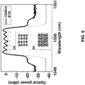
- FIG. 6 shows the optical spectra before and after 1200-km SMF-28 transmission with EDFA-only amplification.
- the obtained corresponding constellations are inserted in FIG. 6 as (a) and (b), respectively.
- the OSNR of the signal after transmission over 1200-km SF-28 is 23.6 dB.
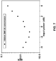
- FIG. 7 depicts the varying BER performance of the N-WDM channel at 1550.10 nm after 1200-km SMF-28 transmission by changing the launched power into each span fiber.
- FIG. 8 depicts the varying BER performance of the N-WDM channel at 1550.10 nm after transmission by changing the transmission distance, in the case of the launched power of -1 dBm/channel.
- the BER for each of the 6 channels is smaller than the limitation of FEC limit of 3.8 ⁇ 10 -3 .
- FIG. 10 is a flow chart representation of a process 1000 of optical communication.
- the process 1000 may be implemented, for example, at a transmitter-side.
- a test signal is transmitted over an optical communication medium using a first optical modulation format.
- the test signal may comprise a binary phase shift keying signal that may be passed through a wavelength selective switch.
- a reception report for the test signal may include, e.g., a transfer function estimate computed by a receiver.
- a pre-equalization scheme is determined.
- the pre-equalization scheme may, e.g., select a pre-equalization filter that compensates the estimated channel transfer function (e.g., reciprocal of the estimated channel function).
- Other pre-equalization schemes are disclosed in the present document.
- the determined pre-equalization scheme is applied to data to be transmitted at a transmitter side to generate pre-equalized data.
- data may be filtered through the inverse channel transfer function filter.
- the data may be modulated using 16 QAM or another modulation technique prior to pre-equalization.
- the data may be modulated prior to the application of pre-equalization filter.
- the data may be modulated after the application of a pre-equalization technique (e.g., error correction coding or filtering).
- FIG. 11 is a block diagram representation of an apparatus 1100 for optical communication.
- the module 1102 is for transmitting a test signal over an optical communication medium using a first optical modulation format.
- the module 1104 is for receiving a reception report for the test signal.
- the module 1106 is for determining, based on the received reception report, a pre-equalization scheme.
- the module 1108 is for applying the pre-equalization scheme to data to be transmitted at a transmitter side to generate pre-equalized data.
- the module 1110 is for transmitting the pre-equalized data over the optical communication medium using a second optical modulation format based on the reception report.
- the apparatus 1100 and modules 1102, 1104, 1106, 1108 and 1110 may be further configured to perform some of the techniques disclosed in this document.
- the Nyquist wavelength-division multiplexing technique enables a solution to achieve high spectral efficiency in long-haul transmission system.
- a polarization division multiplexing quadrature-phase-shift-keying, even high-level modulation scheme such as polarization division multiplexing 16-quadrature-amplitude-modulation is much more sensitive to intra-channel noise and inter-channel linear crosstalk caused by Nyquist wavelength-division multiplexing.
- optical transmission techniques that use higher modulation schemes, such as 16 QAM, are disclosed.
- modules and the functional operations can be implemented in digital electronic circuitry, or in computer software, firmware, or hardware, including the structures disclosed in this document and their structural equivalents, or in combinations of one or more of them.
- the disclosed and other embodiments can be implemented as one or more computer program products, i.e., one or more modules of computer program instructions encoded on a computer readable medium for execution by, or to control the operation of, data processing apparatus.
- the computer readable medium can be a machine-readable storage device, a machine-readable storage substrate, a memory device, a composition of matter effecting a machine-readable propagated signal, or a combination of one or more them.
- data processing apparatus encompasses all apparatus, devices, and machines for processing data, including by way of example a programmable processor, a computer, or multiple processors or computers.
- the apparatus can include, in addition to hardware, code that creates an execution environment for the computer program in question, e.g., code that constitutes processor firmware, a protocol stack, a database management system, an operating system, or a combination of one or more of them.
- a propagated signal is an artificially generated signal, e.g., a machine-generated electrical, optical, or electromagnetic signal, that is generated to encode information for transmission to suitable receiver apparatus.
- a computer program (also known as a program, software, software application, script, or code) can be written in any form of programming language, including compiled or interpreted languages, and it can be deployed in any form, including as a stand alone program or as a module, component, subroutine, or other unit suitable for use in a computing environment.
- a computer program does not necessarily correspond to a file in a file system.
- a program can be stored in a portion of a file that holds other programs or data (e.g., one or more scripts stored in a markup language document), in a single file dedicated to the program in question, or in multiple coordinated files (e.g., files that store one or more modules, sub programs, or portions of code).
- a computer program can be deployed to be executed on one computer or on multiple computers that are located at one site or distributed across multiple sites and interconnected by a communication network.
- the processes and logic flows described in this document can be performed by one or more programmable processors executing one or more computer programs to perform functions by operating on input data and generating output.
- the processes and logic flows can also be performed by, and apparatus can also be implemented as, special purpose logic circuitry, e.g., an FPGA (field programmable gate array) or an ASIC (application specific integrated circuit).
- processors suitable for the execution of a computer program include, by way of example, both general and special purpose microprocessors, and any one or more processors of any kind of digital computer.
- a processor will receive instructions and data from a read only memory or a random access memory or both.
- the essential elements of a computer are a processor for performing instructions and one or more memory devices for storing instructions and data.
- a computer will also include, or be operatively coupled to receive data from or transfer data to, or both, one or more mass storage devices for storing data, e.g., magnetic, magneto optical disks, or optical disks.
- mass storage devices for storing data, e.g., magnetic, magneto optical disks, or optical disks.
- a computer need not have such devices.
- Computer readable media suitable for storing computer program instructions and data include all forms of non volatile memory, media and memory devices, including by way of example semiconductor memory devices, e.g., EPROM, EEPROM, and flash memory devices; magnetic disks, e.g., internal hard disks or removable disks; magneto optical disks; and CD ROM and DVD-ROM disks.
- semiconductor memory devices e.g., EPROM, EEPROM, and flash memory devices
- magnetic disks e.g., internal hard disks or removable disks
- magneto optical disks e.g., CD ROM and DVD-ROM disks.
- the processor and the memory can be supplemented by, or incorporated in, special purpose logic circuitry.
Landscapes
- Physics & Mathematics (AREA)
- Electromagnetism (AREA)
- Engineering & Computer Science (AREA)
- Computer Networks & Wireless Communication (AREA)
- Signal Processing (AREA)
- Optics & Photonics (AREA)
- Optical Communication System (AREA)
- Digital Transmission Methods That Use Modulated Carrier Waves (AREA)
Claims (12)
- Procédé de communication optique, comprenant :la transmission (1002) d'un signal de test sur un support de communication optique à l'aide d'un premier format de modulation optique ;la réception (1004) d'un rapport de réception du signal de test ;la détermination (1006), sur la base du rapport de réception reçu, d'un schéma de pré-égalisation ;l'application (1008) du schéma de pré-égalisation à des données à transmettre du côté transmetteur pour générer des données pré-égalisées ; etla transmission (1010) des données pré-égalisées sur le support de communication optique à l'aide d'un second format de modulation optique différent du premier format de modulation optique basé sur le rapport de réception,le signal de test étant généré à l'aide d'un premier commutateur sélectif de longueur d'onde (WSS), et les données pré-égalisées étant traitées à l'aide un second WSS qui a une bande passante différente de celle du premier WSS.
- Procédé selon la revendication 1, dans lequel le premier format de modulation optique comprend une modulation par déplacement de phase binaire (BPSK).
- Procédé selon la revendication 1, dans lequel le second format de modulation optique comprend un multiplexage par répartition en longueur d'onde de Nyquist.
- Procédé selon la revendication 3, dans lequel le second format de modulation optique comprend en outre un multiplexage par division de polarisation basé sur une modulation d'amplitude en quadrature QAM16.
- Procédé selon la revendication 1, dans lequel le rapport de réception comprend des informations sur une fonction de transfert estimée du support de communication optique.
- Appareil de communication optique, comprenant :un transmetteur de signal de test (1102) adapté pour transmettre un signal de test sur un support de communication optique à l'aide d'un premier format de modulation optique ;un récepteur de rapport de réception (1104) adapté pour recevoir un rapport de réception du signal de test ;un dispositif de détermination de schéma de pré-égalisation (1106) adapté pour déterminer, sur la base du rapport de réception reçu, un schéma de pré-égalisation ;un pré-égaliseur (1108) adapté pour appliquer le schéma de pré-égalisation à des données à transmettre du côté transmetteur pour générer des données pré-égalisées ; etun transmetteur de données (1110) adapté pour transmettre les données pré-égalisées sur le support de communication optique à l'aide d'un deuxième format de modulation optique différent du premier format de modulation optique basé sur le rapport de réception,le signal de test étant généré à l'aide d'un premier commutateur sélectif de longueur d'onde (WSS), et les données pré-égalisées étant traitées à l'aide d'un second WSS qui a une bande passante différente de celle du premier WSS.
- Appareil selon la revendication 6, dans lequel le premier format de modulation optique comprend une modulation par déplacement de phase binaire (BPSK).
- Appareil selon la revendication 6, dans lequel le second format de modulation optique comprend un multiplexage par répartition en longueur d'onde de Nyquist.
- Appareil selon la revendication 8, dans lequel le second format de modulation optique comprend en outre un multiplexage par division de polarisation basé sur une modulation d'amplitude en quadrature QAM16.
- Appareil selon la revendication 6, dans lequel le rapport de réception comprend des informations sur une fonction de transfert estimée du support de communication optique.
- Appareil de communication optique, comprenant :une mémoire qui stocke des instructions ; etun processeur qui lit les instructions et commande des opérations, incluant :la transmission (1002) d'un signal de test sur un support de communication optique à l'aide d'un premier format de modulation optique ;la réception (1004) d'un rapport de réception du signal de test ;la détermination (1006), sur la base du rapport de réception reçu, d'un schéma de pré-égalisation ;l'application (1008) du schéma de pré-égalisation à des données à transmettre du côté transmetteur pour générer des données pré-égalisées ; etla transmission (1010) des données pré-égalisées sur le support de communication optique à l'aide d'un second format de modulation optique différent du premier format de modulation optique basé sur le rapport de réception,le signal de test étant généré à l'aide d'un premier commutateur sélectif de longueur d'onde (WSS), et les données pré-égalisées étant traitées à l'aide un second WSS qui a une bande passante différente de celle du premier WSS.
- Système de communication optique, comprenant :l'appareil de transmission optique selon la revendication 6 ; etun appareil de réception optique qui est configuré pour effectuer des opérations comprenant :la réception du signal de test ;le calcul d'une fonction de transfert de canal sur la base du signal de test reçu ; etla transmission du rapport de réception.
Applications Claiming Priority (1)
| Application Number | Priority Date | Filing Date | Title |
|---|---|---|---|
| US201261656491P | 2012-06-06 | 2012-06-06 |
Publications (2)
| Publication Number | Publication Date |
|---|---|
| EP2672638A1 EP2672638A1 (fr) | 2013-12-11 |
| EP2672638B1 true EP2672638B1 (fr) | 2018-04-18 |
Family
ID=48625957
Family Applications (1)
| Application Number | Title | Priority Date | Filing Date |
|---|---|---|---|
| EP13275135.5A Not-in-force EP2672638B1 (fr) | 2012-06-06 | 2013-06-05 | Procédés et appareil pour pré et post égalisation dans des systèmes de communications optiques |
Country Status (4)
| Country | Link |
|---|---|
| US (1) | US9479247B2 (fr) |
| EP (1) | EP2672638B1 (fr) |
| JP (1) | JP5650806B2 (fr) |
| CN (1) | CN103475410B (fr) |
Cited By (1)
| Publication number | Priority date | Publication date | Assignee | Title |
|---|---|---|---|---|
| CN109450552A (zh) * | 2018-11-15 | 2019-03-08 | 武汉邮电科学研究院有限公司 | 一种基于cma的信号均衡方法及系统 |
Families Citing this family (34)
| Publication number | Priority date | Publication date | Assignee | Title |
|---|---|---|---|---|
| JP6058135B2 (ja) | 2012-08-09 | 2017-01-11 | ゼットティーイー(ユーエスエー)インコーポレーテッド | コヒーレントデュオバイナリ整形pm−qpsk信号処理方法及び装置 |
| CN103684600B (zh) * | 2012-09-14 | 2016-08-31 | 富士通株式会社 | 均衡器系数的更新装置和方法、以及接收机和光通信系统 |
| US9880351B2 (en) * | 2013-04-23 | 2018-01-30 | Zte (Usa) Inc. | Directly-modulated multi-polarization optical transmitters |
| US20170019178A1 (en) * | 2014-02-24 | 2017-01-19 | The Regents Of The University Of California | Nonlinearity cancellation in fiber optic transmission based on frequency-mutually-referenced carriers |
| US9564976B2 (en) * | 2014-08-19 | 2017-02-07 | Zte Corporation | Blind equalization of dual subcarrier OFDM signals |
| WO2016051410A1 (fr) * | 2014-10-02 | 2016-04-07 | B.G. Negev Technologies And Applications Ltd., At Ben-Gurion University | Conversion de constellation photonique au silicium entièrement optique de formats de modulation d'amplitude et de phase |
| US9729244B2 (en) | 2014-10-20 | 2017-08-08 | Adva Optical Networking Se | Apparatus and method for monitoring signal quality of a modulated optical signal |
| JP5993042B2 (ja) * | 2015-02-09 | 2016-09-14 | 日本電信電話株式会社 | 光伝送システム及び伝送路補償方法 |
| JP6279500B2 (ja) * | 2015-02-18 | 2018-02-14 | 日本電信電話株式会社 | 光通信システム及び光通信方法 |
| EP3281313B1 (fr) * | 2015-04-10 | 2021-09-01 | National Institute of Information and Communications Technology | Récepteur pour détection auto-homodyne insensible à la polarisation |
| GB2538793A (en) * | 2015-05-29 | 2016-11-30 | Oclaro Tech Ltd | Multiple carrier |
| JP6040288B1 (ja) * | 2015-06-22 | 2016-12-07 | 日本電信電話株式会社 | 光データ伝送システム |
| CN106878207B (zh) | 2015-12-11 | 2021-07-13 | 富士通株式会社 | 测量滤波特性的方法及其装置、预均衡器、通信设备 |
| WO2017145233A1 (fr) * | 2016-02-22 | 2017-08-31 | 三菱電機株式会社 | Émetteur optique |
| CN107294597B (zh) * | 2016-03-31 | 2019-11-08 | 富士通株式会社 | 光发射机和光接收机的频率响应特性的测量装置及方法 |
| CN107592580B (zh) * | 2016-07-08 | 2020-12-25 | 上海诺基亚贝尔股份有限公司 | 光通信方法和装置 |
| CN107919905B (zh) * | 2016-10-10 | 2020-05-22 | 富士通株式会社 | 光接收机频率响应特性不平衡的测量装置及方法 |
| EP3316499A1 (fr) * | 2016-10-27 | 2018-05-02 | Alcatel Lucent | Modulation multi tonalité discrète en sous-quadrature pour atténuation non linéaire |
| US10498456B2 (en) * | 2016-12-19 | 2019-12-03 | Cable Television Laboratories, Inc | System and methods for cable fiber node splitting using coherent optics |
| JP6319487B1 (ja) * | 2017-03-14 | 2018-05-09 | Nttエレクトロニクス株式会社 | 光伝送特性推定方法、光伝送特性補償方法、光伝送特性推定システム及び光伝送特性補償システム |
| US10887022B2 (en) * | 2017-06-15 | 2021-01-05 | Nokia Of America Corporation | Backward propagation with compensation of some nonlinear effects of polarization mode dispersion |
| JP6673881B2 (ja) * | 2017-08-25 | 2020-03-25 | 日本電信電話株式会社 | 光伝送特性補償システム及び光伝送特性補償方法 |
| US11265084B2 (en) | 2018-12-20 | 2022-03-01 | Acacia Communications, Inc. | Flexible baud rate |
| US10735128B1 (en) * | 2019-03-05 | 2020-08-04 | Rockwell Collins, Inc. | Optical phase sensitivity enhancement for reduced power |
| JP7235963B2 (ja) * | 2019-03-11 | 2023-03-09 | 日本電信電話株式会社 | 光受信機の評価方法及び光受信機の評価装置 |
| US20220357195A1 (en) * | 2019-07-25 | 2022-11-10 | Guangdong Fuan Science & Technology Development Co., Ltd. | Long-distance high-precision optical fiber interference sensing and positioning system |
| CN112511238B (zh) * | 2020-12-28 | 2022-02-22 | 南京信息工程大学 | 一种基于im/dd的自适应偏置分层光ofdm方法 |
| CN113949416B (zh) * | 2021-09-30 | 2022-09-13 | 杭州万高科技股份有限公司 | G3-plc电力载波线系统的非线性预均衡装置和方法 |
| CN114257888B (zh) * | 2021-12-03 | 2023-09-15 | 武汉邮电科学研究院有限公司 | 用于pon系统的自适应编码及均衡方法和pon系统 |
| JP2023102924A (ja) * | 2022-01-13 | 2023-07-26 | 富士通株式会社 | 光受信装置 |
| CN114584870B (zh) * | 2022-02-28 | 2025-01-28 | 武汉光迅科技股份有限公司 | 一种光模块内补偿发端信号频谱不均衡的装置和方法 |
| CN116260693B (zh) * | 2023-02-20 | 2025-10-17 | 北京邮电大学 | 一种基于预均衡的超高阶qam调制传输系统和方法 |
| US12562719B2 (en) | 2023-06-13 | 2026-02-24 | Telefonaktiebolaget Lm Ericsson (Publ) | Signal pre-shaping to suppress power supply disturbances |
| US12609851B2 (en) * | 2023-12-15 | 2026-04-21 | Qualcomm Incorporated | Dynamic pre-equalization switching for wireless transmissions |
Family Cites Families (12)
| Publication number | Priority date | Publication date | Assignee | Title |
|---|---|---|---|---|
| GB2315938B (en) * | 1996-08-01 | 2001-02-28 | Northern Telecom Ltd | Optical transmission system fault analysis |
| JP3370595B2 (ja) * | 1998-03-05 | 2003-01-27 | 日本電信電話株式会社 | プリセット型自動等化装置 |
| US7756421B2 (en) * | 2002-10-03 | 2010-07-13 | Ciena Corporation | Electrical domain compensation of non-linear effects in an optical communications system |
| US7660537B2 (en) * | 2006-03-03 | 2010-02-09 | Alcatel-Lucent Usa Inc. | Simultaneous electrical pre-compensation of self-phase modulation and chromatic dispersion |
| DE102006056158B4 (de) * | 2006-11-28 | 2011-11-17 | Infineon Technologies Ag | Kanalschätzung für OFDM Systeme |
| JP4796183B2 (ja) * | 2007-03-16 | 2011-10-19 | 富士通株式会社 | 光伝送装置 |
| US7986878B2 (en) * | 2008-02-05 | 2011-07-26 | Opnext Subsystems, Inc. | Adjustable bit rate optical transmission using programmable signal modulation |
| JP5128332B2 (ja) * | 2008-03-19 | 2013-01-23 | 株式会社日立製作所 | 光予等化送信器及び光予等化伝送システム |
| JP5174573B2 (ja) * | 2008-07-29 | 2013-04-03 | 三菱電機株式会社 | 予等化光ファイバ通信システム |
| JP2011082749A (ja) | 2009-10-06 | 2011-04-21 | Fujitsu Ltd | 波長モニタ装置 |
| JP5015284B2 (ja) * | 2010-03-30 | 2012-08-29 | 株式会社日立製作所 | 光送信器、光送信方法、及び、光送受信システム |
| JP5786471B2 (ja) * | 2011-06-10 | 2015-09-30 | 住友電気工業株式会社 | 光通信装置 |
-
2013
- 2013-06-05 EP EP13275135.5A patent/EP2672638B1/fr not_active Not-in-force
- 2013-06-05 JP JP2013118738A patent/JP5650806B2/ja not_active Expired - Fee Related
- 2013-06-06 CN CN201310223370.7A patent/CN103475410B/zh not_active Expired - Fee Related
- 2013-06-06 US US13/912,138 patent/US9479247B2/en not_active Expired - Fee Related
Non-Patent Citations (1)
| Title |
|---|
| None * |
Cited By (1)
| Publication number | Priority date | Publication date | Assignee | Title |
|---|---|---|---|---|
| CN109450552A (zh) * | 2018-11-15 | 2019-03-08 | 武汉邮电科学研究院有限公司 | 一种基于cma的信号均衡方法及系统 |
Also Published As
| Publication number | Publication date |
|---|---|
| CN103475410A (zh) | 2013-12-25 |
| JP2014042229A (ja) | 2014-03-06 |
| EP2672638A1 (fr) | 2013-12-11 |
| US9479247B2 (en) | 2016-10-25 |
| CN103475410B (zh) | 2016-09-28 |
| US20130330070A1 (en) | 2013-12-12 |
| JP5650806B2 (ja) | 2015-01-07 |
Similar Documents
| Publication | Publication Date | Title |
|---|---|---|
| EP2672638B1 (fr) | Procédés et appareil pour pré et post égalisation dans des systèmes de communications optiques | |
| US9698914B2 (en) | Recovering data from quadrature phase shift keying modulated optical signals | |
| US9941974B2 (en) | Techniques for receiving DFT spreading modulation signals | |
| Qian et al. | High capacity/spectral efficiency 101.7-Tb/s WDM transmission using PDM-128QAM-OFDM over 165-km SSMF within C-and L-bands | |
| Randel et al. | All-electronic flexibly programmable 864-Gb/s single-carrier PDM-64-QAM | |
| Yu et al. | Transmission of 200 G PDM-CSRZ-QPSK and PDM-16 QAM with a SE of 4 b/s/Hz | |
| Zhou et al. | Advanced DSP for 400 Gb/s and beyond optical networks | |
| US9564976B2 (en) | Blind equalization of dual subcarrier OFDM signals | |
| Olmedo et al. | Towards 400GBASE 4-lane solution using direct detection of MultiCAP signal in 14 GHz bandwidth per lane | |
| Dong et al. | 6$\,\times\, $144-Gb/s Nyquist-WDM PDM-64QAM Generation and Transmission on a 12-GHz WDM Grid Equipped With Nyquist-Band Pre-Equalization | |
| Dong et al. | 6$\,\times\, $128-Gb/s Nyquist-WDM PDM-16QAM Generation and Transmission Over 1200-km SMF-28 With SE of 7.47 b/s/Hz | |
| US9225429B2 (en) | Recovering data from quadrature phase shift keying modulated optical signals | |
| WO2015027903A1 (fr) | Communication optique utilisant des signaux super-nyquist | |
| Zhu et al. | Terabit faster-than-Nyquist PDM 16-QAM WDM transmission with a net spectral efficiency of 7.96 b/s/Hz | |
| US20190319712A1 (en) | Amplitude coherent detection for pulse amplitude modulation signals | |
| US9590833B2 (en) | Reception of 2-subcarriers coherent orthogonal frequency division multiplexed signals | |
| Zhu et al. | Single carrier 400G transmission with single-ended heterodyne detection | |
| Rios-Muller et al. | Experimental comparison between hybrid-QPSK/8QAM and 4D-32SP-16QAM formats at 31.2 GBaud using Nyquist pulse shaping | |
| Dong et al. | 7$\,\times\, $224 Gb/s/ch Nyquist-WDM Transmission Over 1600-km SMF-28 Using PDM-CSRZ-QPSK Modulation | |
| WO2012003856A1 (fr) | Procédé et dispositif de traitement de données dans un réseau de communication optique | |
| Poggiolini et al. | Performance dependence on channel baud-rate of PM-QPSK systems over uncompensated links | |
| Chen et al. | Comparison of advanced detection techniques for QPSK signals in super-Nyquist WDM systems | |
| Lu et al. | Experimental comparison of 32-Gbaud Electrical-OFDM and Nyquist-WDM transmission with 64GSa/s DAC | |
| Bosco | Flexible transceivers and the rate/reach trade-off | |
| Clausen et al. | Experimental demonstration of flexible hybrid modulation formats for future adaptive optical transmission systems |
Legal Events
| Date | Code | Title | Description |
|---|---|---|---|
| PUAI | Public reference made under article 153(3) epc to a published international application that has entered the european phase |
Free format text: ORIGINAL CODE: 0009012 |
|
| AK | Designated contracting states |
Kind code of ref document: A1 Designated state(s): AL AT BE BG CH CY CZ DE DK EE ES FI FR GB GR HR HU IE IS IT LI LT LU LV MC MK MT NL NO PL PT RO RS SE SI SK SM TR |
|
| AX | Request for extension of the european patent |
Extension state: BA ME |
|
| 17P | Request for examination filed |
Effective date: 20140611 |
|
| RAP1 | Party data changed (applicant data changed or rights of an application transferred) |
Owner name: ZTE (USA) INC. |
|
| RAP1 | Party data changed (applicant data changed or rights of an application transferred) |
Owner name: ZTE (USA) INC. |
|
| GRAP | Despatch of communication of intention to grant a patent |
Free format text: ORIGINAL CODE: EPIDOSNIGR1 |
|
| STAA | Information on the status of an ep patent application or granted ep patent |
Free format text: STATUS: GRANT OF PATENT IS INTENDED |
|
| RIC1 | Information provided on ipc code assigned before grant |
Ipc: H04B 10/50 20130101ALI20171013BHEP Ipc: H04B 10/2507 20130101AFI20171013BHEP Ipc: H04B 10/073 20130101ALI20171013BHEP Ipc: H04B 10/54 20130101ALI20171013BHEP |
|
| INTG | Intention to grant announced |
Effective date: 20171031 |
|
| GRAS | Grant fee paid |
Free format text: ORIGINAL CODE: EPIDOSNIGR3 |
|
| GRAA | (expected) grant |
Free format text: ORIGINAL CODE: 0009210 |
|
| STAA | Information on the status of an ep patent application or granted ep patent |
Free format text: STATUS: THE PATENT HAS BEEN GRANTED |
|
| AK | Designated contracting states |
Kind code of ref document: B1 Designated state(s): AL AT BE BG CH CY CZ DE DK EE ES FI FR GB GR HR HU IE IS IT LI LT LU LV MC MK MT NL NO PL PT RO RS SE SI SK SM TR |
|
| REG | Reference to a national code |
Ref country code: GB Ref legal event code: FG4D |
|
| REG | Reference to a national code |
Ref country code: CH Ref legal event code: EP |
|
| REG | Reference to a national code |
Ref country code: AT Ref legal event code: REF Ref document number: 991525 Country of ref document: AT Kind code of ref document: T Effective date: 20180515 |
|
| REG | Reference to a national code |
Ref country code: IE Ref legal event code: FG4D |
|
| REG | Reference to a national code |
Ref country code: DE Ref legal event code: R096 Ref document number: 602013036030 Country of ref document: DE |
|
| REG | Reference to a national code |
Ref country code: FR Ref legal event code: PLFP Year of fee payment: 6 |
|
| REG | Reference to a national code |
Ref country code: NL Ref legal event code: MP Effective date: 20180418 |
|
| REG | Reference to a national code |
Ref country code: LT Ref legal event code: MG4D |
|
| PG25 | Lapsed in a contracting state [announced via postgrant information from national office to epo] |
Ref country code: NL Free format text: LAPSE BECAUSE OF FAILURE TO SUBMIT A TRANSLATION OF THE DESCRIPTION OR TO PAY THE FEE WITHIN THE PRESCRIBED TIME-LIMIT Effective date: 20180418 |
|
| PG25 | Lapsed in a contracting state [announced via postgrant information from national office to epo] |
Ref country code: BG Free format text: LAPSE BECAUSE OF FAILURE TO SUBMIT A TRANSLATION OF THE DESCRIPTION OR TO PAY THE FEE WITHIN THE PRESCRIBED TIME-LIMIT Effective date: 20180718 Ref country code: FI Free format text: LAPSE BECAUSE OF FAILURE TO SUBMIT A TRANSLATION OF THE DESCRIPTION OR TO PAY THE FEE WITHIN THE PRESCRIBED TIME-LIMIT Effective date: 20180418 Ref country code: AL Free format text: LAPSE BECAUSE OF FAILURE TO SUBMIT A TRANSLATION OF THE DESCRIPTION OR TO PAY THE FEE WITHIN THE PRESCRIBED TIME-LIMIT Effective date: 20180418 Ref country code: NO Free format text: LAPSE BECAUSE OF FAILURE TO SUBMIT A TRANSLATION OF THE DESCRIPTION OR TO PAY THE FEE WITHIN THE PRESCRIBED TIME-LIMIT Effective date: 20180718 Ref country code: PL Free format text: LAPSE BECAUSE OF FAILURE TO SUBMIT A TRANSLATION OF THE DESCRIPTION OR TO PAY THE FEE WITHIN THE PRESCRIBED TIME-LIMIT Effective date: 20180418 Ref country code: SE Free format text: LAPSE BECAUSE OF FAILURE TO SUBMIT A TRANSLATION OF THE DESCRIPTION OR TO PAY THE FEE WITHIN THE PRESCRIBED TIME-LIMIT Effective date: 20180418 Ref country code: LT Free format text: LAPSE BECAUSE OF FAILURE TO SUBMIT A TRANSLATION OF THE DESCRIPTION OR TO PAY THE FEE WITHIN THE PRESCRIBED TIME-LIMIT Effective date: 20180418 Ref country code: ES Free format text: LAPSE BECAUSE OF FAILURE TO SUBMIT A TRANSLATION OF THE DESCRIPTION OR TO PAY THE FEE WITHIN THE PRESCRIBED TIME-LIMIT Effective date: 20180418 |
|
| PG25 | Lapsed in a contracting state [announced via postgrant information from national office to epo] |
Ref country code: RS Free format text: LAPSE BECAUSE OF FAILURE TO SUBMIT A TRANSLATION OF THE DESCRIPTION OR TO PAY THE FEE WITHIN THE PRESCRIBED TIME-LIMIT Effective date: 20180418 Ref country code: HR Free format text: LAPSE BECAUSE OF FAILURE TO SUBMIT A TRANSLATION OF THE DESCRIPTION OR TO PAY THE FEE WITHIN THE PRESCRIBED TIME-LIMIT Effective date: 20180418 Ref country code: GR Free format text: LAPSE BECAUSE OF FAILURE TO SUBMIT A TRANSLATION OF THE DESCRIPTION OR TO PAY THE FEE WITHIN THE PRESCRIBED TIME-LIMIT Effective date: 20180719 Ref country code: LV Free format text: LAPSE BECAUSE OF FAILURE TO SUBMIT A TRANSLATION OF THE DESCRIPTION OR TO PAY THE FEE WITHIN THE PRESCRIBED TIME-LIMIT Effective date: 20180418 |
|
| REG | Reference to a national code |
Ref country code: AT Ref legal event code: MK05 Ref document number: 991525 Country of ref document: AT Kind code of ref document: T Effective date: 20180418 |
|
| PG25 | Lapsed in a contracting state [announced via postgrant information from national office to epo] |
Ref country code: PT Free format text: LAPSE BECAUSE OF FAILURE TO SUBMIT A TRANSLATION OF THE DESCRIPTION OR TO PAY THE FEE WITHIN THE PRESCRIBED TIME-LIMIT Effective date: 20180820 |
|
| REG | Reference to a national code |
Ref country code: DE Ref legal event code: R097 Ref document number: 602013036030 Country of ref document: DE |
|
| PG25 | Lapsed in a contracting state [announced via postgrant information from national office to epo] |
Ref country code: EE Free format text: LAPSE BECAUSE OF FAILURE TO SUBMIT A TRANSLATION OF THE DESCRIPTION OR TO PAY THE FEE WITHIN THE PRESCRIBED TIME-LIMIT Effective date: 20180418 Ref country code: SK Free format text: LAPSE BECAUSE OF FAILURE TO SUBMIT A TRANSLATION OF THE DESCRIPTION OR TO PAY THE FEE WITHIN THE PRESCRIBED TIME-LIMIT Effective date: 20180418 Ref country code: DK Free format text: LAPSE BECAUSE OF FAILURE TO SUBMIT A TRANSLATION OF THE DESCRIPTION OR TO PAY THE FEE WITHIN THE PRESCRIBED TIME-LIMIT Effective date: 20180418 Ref country code: AT Free format text: LAPSE BECAUSE OF FAILURE TO SUBMIT A TRANSLATION OF THE DESCRIPTION OR TO PAY THE FEE WITHIN THE PRESCRIBED TIME-LIMIT Effective date: 20180418 Ref country code: RO Free format text: LAPSE BECAUSE OF FAILURE TO SUBMIT A TRANSLATION OF THE DESCRIPTION OR TO PAY THE FEE WITHIN THE PRESCRIBED TIME-LIMIT Effective date: 20180418 Ref country code: CZ Free format text: LAPSE BECAUSE OF FAILURE TO SUBMIT A TRANSLATION OF THE DESCRIPTION OR TO PAY THE FEE WITHIN THE PRESCRIBED TIME-LIMIT Effective date: 20180418 |
|
| REG | Reference to a national code |
Ref country code: CH Ref legal event code: PL |
|
| PLBE | No opposition filed within time limit |
Free format text: ORIGINAL CODE: 0009261 |
|
| STAA | Information on the status of an ep patent application or granted ep patent |
Free format text: STATUS: NO OPPOSITION FILED WITHIN TIME LIMIT |
|
| PG25 | Lapsed in a contracting state [announced via postgrant information from national office to epo] |
Ref country code: SM Free format text: LAPSE BECAUSE OF FAILURE TO SUBMIT A TRANSLATION OF THE DESCRIPTION OR TO PAY THE FEE WITHIN THE PRESCRIBED TIME-LIMIT Effective date: 20180418 Ref country code: IT Free format text: LAPSE BECAUSE OF FAILURE TO SUBMIT A TRANSLATION OF THE DESCRIPTION OR TO PAY THE FEE WITHIN THE PRESCRIBED TIME-LIMIT Effective date: 20180418 |
|
| REG | Reference to a national code |
Ref country code: BE Ref legal event code: MM Effective date: 20180630 |
|
| REG | Reference to a national code |
Ref country code: IE Ref legal event code: MM4A |
|
| 26N | No opposition filed |
Effective date: 20190121 |
|
| PG25 | Lapsed in a contracting state [announced via postgrant information from national office to epo] |
Ref country code: LU Free format text: LAPSE BECAUSE OF NON-PAYMENT OF DUE FEES Effective date: 20180605 Ref country code: MC Free format text: LAPSE BECAUSE OF FAILURE TO SUBMIT A TRANSLATION OF THE DESCRIPTION OR TO PAY THE FEE WITHIN THE PRESCRIBED TIME-LIMIT Effective date: 20180418 |
|
| PG25 | Lapsed in a contracting state [announced via postgrant information from national office to epo] |
Ref country code: CH Free format text: LAPSE BECAUSE OF NON-PAYMENT OF DUE FEES Effective date: 20180630 Ref country code: LI Free format text: LAPSE BECAUSE OF NON-PAYMENT OF DUE FEES Effective date: 20180630 Ref country code: IE Free format text: LAPSE BECAUSE OF NON-PAYMENT OF DUE FEES Effective date: 20180605 |
|
| PG25 | Lapsed in a contracting state [announced via postgrant information from national office to epo] |
Ref country code: BE Free format text: LAPSE BECAUSE OF NON-PAYMENT OF DUE FEES Effective date: 20180630 Ref country code: SI Free format text: LAPSE BECAUSE OF FAILURE TO SUBMIT A TRANSLATION OF THE DESCRIPTION OR TO PAY THE FEE WITHIN THE PRESCRIBED TIME-LIMIT Effective date: 20180418 |
|
| PG25 | Lapsed in a contracting state [announced via postgrant information from national office to epo] |
Ref country code: MT Free format text: LAPSE BECAUSE OF NON-PAYMENT OF DUE FEES Effective date: 20180605 |
|
| PG25 | Lapsed in a contracting state [announced via postgrant information from national office to epo] |
Ref country code: TR Free format text: LAPSE BECAUSE OF FAILURE TO SUBMIT A TRANSLATION OF THE DESCRIPTION OR TO PAY THE FEE WITHIN THE PRESCRIBED TIME-LIMIT Effective date: 20180418 |
|
| PG25 | Lapsed in a contracting state [announced via postgrant information from national office to epo] |
Ref country code: HU Free format text: LAPSE BECAUSE OF FAILURE TO SUBMIT A TRANSLATION OF THE DESCRIPTION OR TO PAY THE FEE WITHIN THE PRESCRIBED TIME-LIMIT; INVALID AB INITIO Effective date: 20130605 |
|
| PG25 | Lapsed in a contracting state [announced via postgrant information from national office to epo] |
Ref country code: MK Free format text: LAPSE BECAUSE OF NON-PAYMENT OF DUE FEES Effective date: 20180418 Ref country code: CY Free format text: LAPSE BECAUSE OF FAILURE TO SUBMIT A TRANSLATION OF THE DESCRIPTION OR TO PAY THE FEE WITHIN THE PRESCRIBED TIME-LIMIT Effective date: 20180418 |
|
| PG25 | Lapsed in a contracting state [announced via postgrant information from national office to epo] |
Ref country code: IS Free format text: LAPSE BECAUSE OF FAILURE TO SUBMIT A TRANSLATION OF THE DESCRIPTION OR TO PAY THE FEE WITHIN THE PRESCRIBED TIME-LIMIT Effective date: 20180818 |
|
| PGFP | Annual fee paid to national office [announced via postgrant information from national office to epo] |
Ref country code: FR Payment date: 20200512 Year of fee payment: 8 Ref country code: DE Payment date: 20200527 Year of fee payment: 8 |
|
| PGFP | Annual fee paid to national office [announced via postgrant information from national office to epo] |
Ref country code: GB Payment date: 20200527 Year of fee payment: 8 |
|
| REG | Reference to a national code |
Ref country code: DE Ref legal event code: R119 Ref document number: 602013036030 Country of ref document: DE |
|
| GBPC | Gb: european patent ceased through non-payment of renewal fee |
Effective date: 20210605 |
|
| PG25 | Lapsed in a contracting state [announced via postgrant information from national office to epo] |
Ref country code: GB Free format text: LAPSE BECAUSE OF NON-PAYMENT OF DUE FEES Effective date: 20210605 Ref country code: DE Free format text: LAPSE BECAUSE OF NON-PAYMENT OF DUE FEES Effective date: 20220101 |
|
| PG25 | Lapsed in a contracting state [announced via postgrant information from national office to epo] |
Ref country code: FR Free format text: LAPSE BECAUSE OF NON-PAYMENT OF DUE FEES Effective date: 20210630 |