EP2672786A2 - Commande d'éclairage et système d'éclairage comprenant celle-ci - Google Patents
Commande d'éclairage et système d'éclairage comprenant celle-ci Download PDFInfo
- Publication number
- EP2672786A2 EP2672786A2 EP20130169412 EP13169412A EP2672786A2 EP 2672786 A2 EP2672786 A2 EP 2672786A2 EP 20130169412 EP20130169412 EP 20130169412 EP 13169412 A EP13169412 A EP 13169412A EP 2672786 A2 EP2672786 A2 EP 2672786A2
- Authority
- EP
- European Patent Office
- Prior art keywords
- color temperature
- light
- curve
- controller
- dial
- Prior art date
- Legal status (The legal status is an assumption and is not a legal conclusion. Google has not performed a legal analysis and makes no representation as to the accuracy of the status listed.)
- Granted
Links
Images




Classifications
-
- H—ELECTRICITY
- H05—ELECTRIC TECHNIQUES NOT OTHERWISE PROVIDED FOR
- H05B—ELECTRIC HEATING; ELECTRIC LIGHT SOURCES NOT OTHERWISE PROVIDED FOR; CIRCUIT ARRANGEMENTS FOR ELECTRIC LIGHT SOURCES, IN GENERAL
- H05B45/00—Circuit arrangements for operating light-emitting diodes [LED]
- H05B45/20—Controlling the colour of the light
-
- H—ELECTRICITY
- H05—ELECTRIC TECHNIQUES NOT OTHERWISE PROVIDED FOR
- H05B—ELECTRIC HEATING; ELECTRIC LIGHT SOURCES NOT OTHERWISE PROVIDED FOR; CIRCUIT ARRANGEMENTS FOR ELECTRIC LIGHT SOURCES, IN GENERAL
- H05B47/00—Circuit arrangements for operating light sources in general, i.e. where the type of light source is not relevant
- H05B47/10—Controlling the light source
- H05B47/17—Operational modes, e.g. switching from manual to automatic mode or prohibiting specific operations
Definitions
- the present invention relates to an illumination controller which controls a light source to change a color temperature and a quantity of light irradiated from the light source, and an illumination system including the same.
- a color temperature and a quantity of light irradiated from a light source have many effects on human psychology. Through many experiments, it has been reported that there is a relationship between the color temperature and the quantity of the irradiated light and human psychology thereunder. Especially, the idea that "upper and lower limits of comfortable illuminance (quantity of light) vary depending on the color temperature” showed by Kruithof in 1941 is widely accepted.
- a high color temperature light e.g., pale light emitted from a daylight white fluorescent lamp, color temperature: ⁇ 5000 K
- a low color temperature light e.g., reddish light emitted from an incandescent lamp, color temperature: ⁇ 2800 K
- a sultry impression to people in a case of high illuminance, but a gentle impression to people if it is adjusted to moderate illuminance.
- an illuminance which makes people feel comfortable or uncomfortable varies depending on the color temperature of the irradiated light.
- Japanese Patent Laid-open Publication No. 2009-117080 discloses an apparatus in which the quantity and the color temperature of irradiated light are changed only in the region where people feel comfortable, as shown in FIG. 7 .
- the quantity and the color temperature of the irradiated light are adjusted manually, it is difficult for general users, who do not have expertise in illumination, to adjust the quantity and the color temperature of the irradiated light while keeping a good balance thereof. Also, it is difficult for general users to set them according to the illumination environment such as a location or a time zone in which the illumination apparatus is used.
- the present invention provides an illumination controller that even general users can use to adjust a quantity and a color temperature of light irradiated from a light source while keeping a good balance thereof and easily to set them according to the illumination environment, and an illumination system including the same.
- an illumination controller which controls a light source unit having a plurality of light sources that emit different colored lights, including: a dial, which is rotatable, used to adjust a color temperature and a quantity of light irradiated from the light source unit, a memory which stores one or more control curves in which the color temperature and the quantity of light irradiated from the light source unit change in conjunction with each other; and a curve selection unit used to select one curve among the control curves stored in the memory, wherein when the dial is rotated, the color temperature and the quantity of light irradiated from the light source unit change according to values defined on the control curve selected by the curve selection unit.
- the curve selection unit may include one or more curve selection buttons used to select one control curve among the control curves.
- the dial may be formed of a disc-shaped knob which is adapted to be pressed in a direction perpendicular to a rotational plane of the dial. Accordingly, the dial may function as the curve selection unit when it is pressed.
- the controller may further include a display unit configured to indicate a currently selected control curve.
- an illumination system including the illumination controller as described above.
- the illumination system may further include a timer configured to start and terminate an operation of the controller at a preset time.
- the control curves preferably include a normal mode curve in which a variation width of the quantity of light to a variation width of the color temperature is large in a low color temperature range, and is small in a high color temperature range.
- the control curves may further include a wakeup mode curve in which each of the quantity of light and the color temperature increases monotonically with the time at wakeup time.
- control curves may include a bedtime mode curve in which the quantity of light rises as the color temperature of light increases in a low color temperature range, while the color temperature of light is prevented from becoming a high color temperature.
- the quantity and the color temperature of the irradiated light change changed according to the control curve in which the color temperature and the quantity of the irradiated light vary in conjunction with each other, even general users can adjust the quantity and the color temperature of the irradiated light while keeping a good balance thereof. Further, since a plurality of control curves are provided, it is possible to easily set the quantity and the color temperature of light by appropriately selecting the control curve proper to the illumination environment.
- a color temperature variable illumination system (hereinafter, referred to as an illumination system) in accordance with an embodiment of the present invention will be described with reference to FIGS. 1 to 4 .
- an illumination system 1 includes a light source unit 2, a power source unit 3 for supplying a power to the light source unit 2, and a controller 4 for controlling an operation of the power source unit 3 in response to an input from a user. Further, the illumination system 1 includes a timer 5 for starting and terminating an operation of the controller 4 at a predetermined time.
- the timer 5 is configured such that the current time, and the operation start time and operation end time of the controller 4 can be set. Accordingly, the timer 5 controls the operation of the controller 4 by transmitting a trigger signal to the controller 4 when it reaches a specified time.
- the light source unit 2 has multiple types of light sources that emit different colored lights.
- the light source unit 2 has a red light source 2R (R: Red) that emits red light, a green light source 2G (G: Green) that emits green light, and a blue light source 2B (B: Blue) that emits blue light.
- the red light source 2R is constituted by a plurality of red LEDs connected in series to each other.
- the green light source 2G is constituted by a plurality of green LEDs connected in series to each other.
- the blue light source 2B is constituted by a plurality of blue LEDs connected in series to each other.
- the controller 4 includes a housing 41 which is fixed to, e.g., a wall surface of a room where the illumination system 1 is installed.
- the housing 41 has a rectangular box shape.
- a power switch 42 for turning on and off the light source unit 2
- a rotatable dial 6 used to adjust a color temperature and a quantity of the light emitted from the light source unit 2.
- a plurality of marks 61 and 62 is provided to indicate a rotation location of the dial 6.
- the power switch 42 is formed of a push-button switch that opens and closes a circuit supplying power from an alternating current power source (AC) to the power source unit 3.
- AC alternating current power source
- the dial 6 is provided as a disc-shaped knob, and has a marking 63 for indicating its own rotational position on the surface thereof.
- the dial 6 rotates within a certain range, and upper and lower limits of the color temperature and the quantity of irradiation light are set within this rotation range.
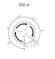
- the dial 6 is configured such that the marking 63 is rotatable by approximately 300° between the mark 61 and the mark 62.
- the marking 63 meets the mark 61, the quantity and the color temperature of light irradiated from the light source unit 2 become the minimum.
- the marking 63 meets the mark 62, the quantity and the color temperature of irradiation light from the light source unit 2 become the maximum.
- the dial 6 may be configured to be rotated smoothly or may be configured to click when it is rotated.
- the controller 4 includes a memory 43 for storing a plurality of control curves defined such that the color temperature and the quantity of irradiation light changes in conjunction with each other, and a curve selection unit 7 for selecting one curve among the control curves stored in the memory 43.
- the curve selection unit 7 includes three curve selection buttons 71, 72 and 73. The control curves and the curve selection unit 7 will be described later in detail.
- the controller 4 has a control unit 44 for generating a control signal to control the light source unit 2 in response to an input from the user.
- the power source unit 3 includes a control signal input unit 31 to which a control signal generated by the control unit 44 is inputted, and an AC/DC converter 32 which converts an AC voltage, supplied from the AC power source through the controller 4, into a desired DC voltage. Further, the power source unit 3 includes a red light driver 33R for driving the red light source 2R, a green light driver 33G for driving the green light source 2G, and a blue light driver 33B for driving the blue light source 2B. Furthermore, the power source unit 3 includes a drive signal conversion unit 34 that converts the control signal inputted through the control signal input unit 31 into a drive signal for driving each of the drivers 33R, 33G, and 33B. The drive signal conversion unit 34 outputs a drive signal of a square wave signal having a variable on-duty ratio and a predetermined period.
- each of the drivers 33R, 33G, and 33B has a resistor R as a current limiter, and the resistor R is inserted between the anode of each of the light sources 2R, 2G and 2B and the positive (+) terminal of the AC/DC converter 32.
- each of the drivers 33R, 33G and 33B has a switching element Q1 which is connected to the cathode of each of the light sources 2R, 2G, and 2B, and the drain of the switching element Q1 is connected to the negative (-) terminal (ground) of the AC/DC converter 32.
- the switching element Q1 is formed of a field effect transistor.
- each of the drivers 33R, 33G and 33B has a waveform shaping circuit including two transistors Tr1 and Tr2 connected in parallel to each other.
- the transistor Tr1 is constituted by a PNP bipolar transistor having a collector connected to the positive (+) terminal of the AC/DC converter 32 and an emitter connected to the gate of the switching element Q1.
- the transistor Tr2 is constituted by an NPN bipolar transistor having a collector connected to the gate of the switching element Q1 and an emitter connected to the negative (-) terminal of the AC/DC converter 32.
- the waveform shaping circuit performs pulse width modulation (PWM) control on the switching element Q1 based on a drive signal inputted to bases of the transistors Tr1 and Tr2 from the drive signal conversion unit 34, thereby adjusting the amount of power supplied to each of the light sources 2R, 2G, and 2B.
- PWM pulse width modulation
- the color temperature and the quantity of light irradiated from the light source unit 2 change according to the values determined by one of the plurality of control curves.
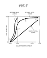
- the plurality of control curves include at least one of, e.g., a normal mode curve used in a normal state, a wakeup mode curve used at wakeup time, and a bedtime mode curve used at bedtime.
- the normal mode curve, the wakeup mode curve and the bedtime mode curve are assigned to the curve selection buttons 71, 72, and 73, respectively, and each curve can be selected by pressing the corresponding button.
- the light power is represented as a percentage to the maximum power of the light source unit 2.
- the normal mode curve is defined such that a variation width of a light power (i.e., quantity of light) to a variation width of the color temperature is great in a low color temperature range ( ⁇ 3000 K), and small in a high color temperature range ( ⁇ 3000 K).
- a rated power of light is sufficient for normal use in a high color temperature range, and increasing the quantity of light is undesirable from an energy saving point of view. Therefore, in the normal mode curve, an increase of the light power (quantity of light) is suppressed in the high color temperature range.
- the wakeup mode curve is defined such that both of the quantity and the color temperature of irradiation light increase monotonically with the time at wakeup time. Since the color temperature and the quantity of irradiation light gradually increase, the user can wake up pleasantly without an uncomfortable feeling.
- the illumination system 1 is started at a preset time by the timer 5.
- the bedtime mode curve is defined such that a variation width of a light power (quantity of light) to a variation width of the color temperature is large in a low color temperature range ( ⁇ 3000 K), while the color temperature of the irradiation light is prevented from becoming a high color temperature (> 3000 K).
- melatonin which is a hormone that promotes sleep, is secreted from the pineal gland in the brain at bedtime, and that this secretion of melatonin is suppressed by blue light (light of a high color temperature).
- illumination can be achieved with a sufficient quantity of light when reading a book before going asleep, without interfering with the onset of sleep.
- control curves are defined such that the color temperature and the quantity of irradiation light change in conjunction with each other in a region where people feel comfortable, which is known by Kruithof's experiments.
- Kruithof's experiments it is possible to always obtain the irradiation light which makes the user feel comfortable, while keeping a good balance between the color temperature and the quantity of irradiation light.
- control unit 44 of the controller 4 determines variations in the color temperature and the quantity of light by associating the rotational angle of the dial 6 with the length on the corresponding control curve. This mechanism will be described with reference to FIGS. 3 and 4 by using the normal mode curve as an example.
- the dial 6 is configured such that the marking 63 is rotatable by approximately 300° between the mark 62 and the mark 61 (see FIG. 4 ).
- the color temperature and the quantity of irradiation light when the marking 63 of the dial 6 meets the mark 61 correspond to values defined by end point P (see FIG. 3 ) on the side of the low light power (low quantity of light) and the low color temperature of the normal mode curve.
- the color temperature and the quantity of irradiation light when the marking 63 of the dial 6 meets the mark 62 correspond to values defined by end point Q on the side of the high light power (high quantity of light) and the high color temperature of the normal mode curve.
- L the length between two end points P and Q on the normal mode curve
- the rotational angle of the dial 6 can be corresponded to the variations in the color temperature and the quantity of irradiation light.
- it is possible to smoothly adjust the color temperature and the quantity of irradiation light.
- it facilitates fine adjustment of the light power (quantity of light) and the color temperature in a region (near the point R of FIG. 3 ) where the variation width of the light power to the variation width of the color temperature is large in the control curve, or a region (near the point S of FIG. 3 ) where the variation width of the color temperature to the variation width of the light power is large.
- the illumination system 1 of the present embodiment since the color temperature and the quantity of irradiation light change according to the corresponding control curve, even users who do not have expertise in illumination can adjust the color temperature and the quantity of irradiation light while keeping a good balance therebetween. Further, since a plurality of control curves are provided, it is possible to easily set the color temperature and the quantity of irradiation light, by appropriately selecting the control curve according to the illumination environment such as a location or time zone using the illumination system 1.
- a controller according to a first modification of the above embodiment will be described with reference to FIGS. 5A and 5B .
- a display unit 8 showing a control curve, which is currently selected is provided instead of the curve selection buttons 71 to 73 as the curve selection unit 7.
- the display unit 8 has, e.g., light emitters that emit multiple different colored lights, and notifies the user of the currently selected control curve, by using an emission pattern of the light emitters.
- the display unit 8 may have a liquid crystal panel, and may display the name or the curve shape of the currently selected control curve, or the like, on the liquid crystal panel. Thus, the user can easily know which control curve is being currently selected.
- the dial 6 is configured to be rotatable and pressed in a direction perpendicular to the rotational plane. Accordingly, the dial 6 is rotated to adjust the color temperature and the quantity of irradiation light and is pressed to function as the curve selection unit. Specifically, the dial 6 is configured such that, whenever it is pressed, the control curve is changed in the order of, e.g., the normal mode curve ⁇ the wakeup mode curve ⁇ the bedtime mode curve. In this way, since the dial 6 can also be used as the curve selection unit, the number of components constituting the controller 4a becomes fewer, and assembly efficiency of the controller 4a is improved. Further, appearance of the controller 4a is simplified and improved.
- An illumination system 1a of this modification includes a light source unit 2 having multiple light sources. Further, a controller 4b is provided to collectively control the color temperature and the quantity of light irradiated from the light source unit 2. Each of the light sources includes an internal power source unit (not shown) for driving itself.
- the light source unit 2 includes three light sources 2a, 2b, and 2c in the illustrated example; and the light sources may be identical to each other, or different from each other.
- the controller 4b has a dial 6a for adjusting the light irradiated from the light source 2a, a dial 6b for adjusting the light irradiated from the light source 2b, and a dial 6c for adjusting the light irradiated from the light source 2c.
- the dials 6a, 6b and 6c When rotating each of the dials 6a, 6b and 6c, the color temperature and the quantity of irradiation light from each of the light sources 2a, 2b and 2c are changed to the values determined by the control curve selected by one of the curve selection buttons 71, 72, and 73.
- the characteristics of light irradiated from the light sources 2a, 2b and 2c are independently controlled by dials 6a, 6b, and 6c.
- the manner of control is not limited thereto, and it may be configured such that, for example, the dial 6a is used as a parent dial and the dials 6b and 6c are interlinked with the dial 6a.
- the characteristics of light irradiated from the light sources 2a, 2b and 2c can be controlled collectively by rotating the dial 6a.
- the illumination controller according to the present invention and the illumination system using the same are described, but various modifications can be made without being limited to the above embodiment and its modifications.
- the present illumination system may not have the timer.
- the control curves and the number of the control curves are not limited to the above-described three curves.
- the number of the control curves may be one, two, four or more, and other curves for adjusting according to another illumination environment may be used as the control curves.
- the controller may further include an adjustment button to fine-tune the control curve, and may adjust the color temperature and the quantity of irradiation light by finetuning the control curve using the adjustment button.
Landscapes
- Circuit Arrangement For Electric Light Sources In General (AREA)
Applications Claiming Priority (1)
| Application Number | Priority Date | Filing Date | Title |
|---|---|---|---|
| JP2012130179A JP2013254666A (ja) | 2012-06-07 | 2012-06-07 | 色温度可変照明システム及びそれに用いる照明光源用のコントローラ |
Publications (3)
| Publication Number | Publication Date |
|---|---|
| EP2672786A2 true EP2672786A2 (fr) | 2013-12-11 |
| EP2672786A3 EP2672786A3 (fr) | 2015-06-03 |
| EP2672786B1 EP2672786B1 (fr) | 2018-01-17 |
Family
ID=48485047
Family Applications (1)
| Application Number | Title | Priority Date | Filing Date |
|---|---|---|---|
| EP13169412.7A Active EP2672786B1 (fr) | 2012-06-07 | 2013-05-28 | Commande d'éclairage et système d'éclairage comprenant celle-ci |
Country Status (4)
| Country | Link |
|---|---|
| US (1) | US20130328500A1 (fr) |
| EP (1) | EP2672786B1 (fr) |
| JP (1) | JP2013254666A (fr) |
| CN (1) | CN103491672B (fr) |
Families Citing this family (37)
| Publication number | Priority date | Publication date | Assignee | Title |
|---|---|---|---|---|
| USD713361S1 (en) * | 2013-08-08 | 2014-09-16 | Lutron Electronic Co., Inc. | Tabletop remote load control device |
| USD713360S1 (en) * | 2013-08-08 | 2014-09-16 | Lutron Electronics Co., Inc. | Remote control |
| USD740765S1 (en) * | 2013-12-20 | 2015-10-13 | Cree, Inc. | Configuration tool |
| JP6233585B2 (ja) * | 2014-02-19 | 2017-11-22 | 東芝ライテック株式会社 | 照明器具 |
| USD738320S1 (en) * | 2014-04-17 | 2015-09-08 | Lutron Electronics Co., Inc. | Tabletop remote load control device |
| USD737224S1 (en) * | 2014-04-17 | 2015-08-25 | Lutron Electronics Co., Inc. | Tabletop remote load control device |
| JP6369779B2 (ja) * | 2014-04-17 | 2018-08-08 | パナソニックIpマネジメント株式会社 | 照明器具 |
| JP6296554B2 (ja) * | 2014-10-30 | 2018-03-20 | ミネベアミツミ株式会社 | 調光調色制御装置およびそれを用いた照明制御システム |
| JP6601274B2 (ja) * | 2016-03-04 | 2019-11-06 | 東芝ライテック株式会社 | 照明装置 |
| USD868009S1 (en) * | 2016-06-03 | 2019-11-26 | Lutron Technology Company Llc | Illuminated control device |
| USD814428S1 (en) * | 2016-06-30 | 2018-04-03 | Lutron Electronics Co., Ltd. | Control device |
| USD808912S1 (en) | 2016-06-03 | 2018-01-30 | Lutron Electronics Co., Inc. | Control device |
| USD868010S1 (en) | 2016-06-30 | 2019-11-26 | Lutron Technology Company Llc | Illuminated control device |
| DE102016214048A1 (de) * | 2016-07-29 | 2018-02-01 | Osram Gmbh | Beleuchtungssystem und Verfahren zum Betreiben eines Beleuchtungssystems |
| US9801250B1 (en) | 2016-09-23 | 2017-10-24 | Feit Electric Company, Inc. | Light emitting diode (LED) lighting device or lamp with configurable light qualities |
| US10893587B2 (en) | 2016-09-23 | 2021-01-12 | Feit Electric Company, Inc. | Light emitting diode (LED) lighting device or lamp with configurable light qualities |
| USD805482S1 (en) * | 2016-10-17 | 2017-12-19 | Hunter Fan Company | Remote control |
| US10091855B2 (en) | 2017-01-13 | 2018-10-02 | ETi Solid State Lighting Inc. | Manually controllable LED correlated color temperature light fixture |
| USD837168S1 (en) | 2017-02-16 | 2019-01-01 | Lutron Electronics Co., Inc. | Control device |
| USD837169S1 (en) | 2017-02-16 | 2019-01-01 | Lutron Electronics Co., Inc. | Control device |
| USD951211S1 (en) | 2017-03-16 | 2022-05-10 | Lutron Technology Company Llc | Illuminated control device |
| US10917955B2 (en) | 2017-09-11 | 2021-02-09 | Signify Holding B.V. | Lighting device |
| US10856384B2 (en) | 2018-05-29 | 2020-12-01 | Abl Ip Holding Llc | Lighting system with configurable color temperatures |
| US10952292B2 (en) | 2018-08-09 | 2021-03-16 | Abl Ip Holding Llc | Programmable driver for variable light intensity |
| WO2020056022A1 (fr) * | 2018-09-11 | 2020-03-19 | Lutron Technology Company Llc | Dispositif de commande configuré pour fournir un retour d'informations visuel |
| US10874006B1 (en) | 2019-03-08 | 2020-12-22 | Abl Ip Holding Llc | Lighting fixture controller for controlling color temperature and intensity |
| DE112020001631T5 (de) * | 2019-03-29 | 2022-01-05 | Electronic Theatre Controls, Inc. | Systeme, vorrichtungen und verfahren zur implementierung der spektralen reflexionsbildgebung unter verwendung von schmalbandstrahlern |
| USD935422S1 (en) | 2019-05-01 | 2021-11-09 | Lutron Technology Company Llc | Control device having illumination applied thereto |
| USD921598S1 (en) | 2019-05-20 | 2021-06-08 | Lutron Technology Company Llc | Circular knob and faceplate applied to control device |
| USD892751S1 (en) | 2019-07-12 | 2020-08-11 | Lutron Technology Company Llc | Control device |
| USD892750S1 (en) | 2019-07-12 | 2020-08-11 | Lutron Technology Company Llc | Control device |
| USD933615S1 (en) | 2019-10-15 | 2021-10-19 | Lutron Technology Company Llc | Control device |
| US11641708B2 (en) | 2020-08-28 | 2023-05-02 | Abl Ip Holding Llc | Light fixture controllable via dual networks |
| CN112218403B (zh) * | 2020-11-13 | 2023-12-29 | 珠海雷特科技股份有限公司 | 智能灯具及其亮度色温调节方法、计算机可读存储介质 |
| US11564302B2 (en) | 2020-11-20 | 2023-01-24 | Feit Electric Company, Inc. | Controllable multiple lighting element fixture |
| US11147136B1 (en) | 2020-12-09 | 2021-10-12 | Feit Electric Company, Inc. | Systems and apparatuses for configurable and controllable under cabinet lighting fixtures |
| USD967781S1 (en) * | 2021-03-11 | 2022-10-25 | Lutron Technology Company Llc | Control device |
Citations (1)
| Publication number | Priority date | Publication date | Assignee | Title |
|---|---|---|---|---|
| JP2009117080A (ja) | 2007-11-02 | 2009-05-28 | Sharp Corp | 照明装置 |
Family Cites Families (17)
| Publication number | Priority date | Publication date | Assignee | Title |
|---|---|---|---|---|
| JP2578455Y2 (ja) * | 1992-06-15 | 1998-08-13 | 松下電工株式会社 | 色温度可変照明装置 |
| US7233831B2 (en) * | 1999-07-14 | 2007-06-19 | Color Kinetics Incorporated | Systems and methods for controlling programmable lighting systems |
| WO2004088616A1 (fr) * | 2003-03-28 | 2004-10-14 | Sharp Kabushiki Kaisha | Dispositif d'affichage |
| KR100932344B1 (ko) * | 2005-07-26 | 2009-12-16 | 파나소닉 전공 주식회사 | 조명 시스템 및 수면평가 시스템 |
| US20100084996A1 (en) * | 2007-03-29 | 2010-04-08 | Koninklijke Philips Electronics N.V. | Natural daylight mimicking system and user interface |
| WO2008129485A1 (fr) * | 2007-04-24 | 2008-10-30 | Koninklijke Philips Electronics N. V. | Interface utilisateur à multiples paramètres de commande lumineuse |
| US8330378B2 (en) * | 2009-01-28 | 2012-12-11 | Panasonic Corporation | Illumination device and method for controlling a color temperature of irradiated light |
| CN102413862B (zh) * | 2009-04-23 | 2014-05-07 | 松下电器产业株式会社 | 叫醒系统 |
| JP2010262806A (ja) * | 2009-05-01 | 2010-11-18 | Konica Minolta Holdings Inc | 照明装置および照明システム |
| CN102668697B (zh) * | 2009-10-23 | 2016-05-25 | 特里多尼克有限两合公司 | 具有可变色谱的led灯的运行 |
| DE102010003806A1 (de) * | 2010-04-09 | 2011-10-13 | Zumtobel Lighting Gmbh | Verfahren und Anordnung zum Betreiben einer in ihrer Lichtabgabe veränderlichen Lichtquelle |
| US8632209B2 (en) * | 2010-07-28 | 2014-01-21 | Full Spectrum Solutions | Hybrid source lighting system |
| JP2012199218A (ja) * | 2010-09-09 | 2012-10-18 | Mitsubishi Chemicals Corp | 発光装置、照明システム及び照明方法 |
| CN102507151A (zh) * | 2011-10-25 | 2012-06-20 | 复旦大学 | 一种基于工效学实验的阅读台灯评价方法 |
| JP5895193B2 (ja) * | 2012-03-02 | 2016-03-30 | パナソニックIpマネジメント株式会社 | 照明制御装置、およびこれを用いた照明装置 |
| JP2013254669A (ja) * | 2012-06-07 | 2013-12-19 | Panasonic Corp | 色温度可変照明システム及びそれに用いる照明光源用のコントローラ |
| JP6012009B2 (ja) * | 2012-09-28 | 2016-10-25 | パナソニックIpマネジメント株式会社 | 照明システム |
-
2012
- 2012-06-07 JP JP2012130179A patent/JP2013254666A/ja active Pending
-
2013
- 2013-05-28 EP EP13169412.7A patent/EP2672786B1/fr active Active
- 2013-05-30 US US13/905,272 patent/US20130328500A1/en not_active Abandoned
- 2013-06-07 CN CN201310226528.6A patent/CN103491672B/zh active Active
Patent Citations (1)
| Publication number | Priority date | Publication date | Assignee | Title |
|---|---|---|---|---|
| JP2009117080A (ja) | 2007-11-02 | 2009-05-28 | Sharp Corp | 照明装置 |
Also Published As
| Publication number | Publication date |
|---|---|
| CN103491672A (zh) | 2014-01-01 |
| CN103491672B (zh) | 2016-08-31 |
| US20130328500A1 (en) | 2013-12-12 |
| EP2672786B1 (fr) | 2018-01-17 |
| JP2013254666A (ja) | 2013-12-19 |
| EP2672786A3 (fr) | 2015-06-03 |
Similar Documents
| Publication | Publication Date | Title |
|---|---|---|
| EP2672786A2 (fr) | Commande d'éclairage et système d'éclairage comprenant celle-ci | |
| EP2672785A2 (fr) | Commande d'éclairage et système d'éclairage comprenant celle-ci | |
| CN101839435B (zh) | 照明装置及其控制器 | |
| JP4335210B2 (ja) | 表示装置 | |
| US9137867B2 (en) | Lighting device | |
| EP2608639A1 (fr) | Dispositif d'éclairage | |
| JP2013254665A (ja) | 照明光源用のコントローラ | |
| US10925129B2 (en) | Illumination system including tunable light engine | |
| JP2010176986A (ja) | 色温度可変照明装置並びにそれに用いるコントローラ | |
| JP5406542B2 (ja) | 照明装置 | |
| EP2219418B1 (fr) | Dispositif d'illumination | |
| JP2013048045A (ja) | 照明装置及び照明器具 | |
| TW202102057A (zh) | 發光二極體色彩調諧之使用者控制模態 | |
| CN205657901U (zh) | 照明装置 | |
| US20230160541A1 (en) | Selectable adjustable control for changing color temperature and brightness of an led lamp | |
| JP5663055B2 (ja) | 点灯装置及び照明装置 | |
| JP5807208B2 (ja) | 色温度可変照明装置 | |
| JP5971603B2 (ja) | 色温度可変照明装置 | |
| JP2011233293A (ja) | 照明システム | |
| CN112423421A (zh) | 时控且可依据灯珠光电参数调整的led照明系统 | |
| JP2013168383A (ja) | 点灯装置及び照明装置 |
Legal Events
| Date | Code | Title | Description |
|---|---|---|---|
| PUAI | Public reference made under article 153(3) epc to a published international application that has entered the european phase |
Free format text: ORIGINAL CODE: 0009012 |
|
| AK | Designated contracting states |
Kind code of ref document: A2 Designated state(s): AL AT BE BG CH CY CZ DE DK EE ES FI FR GB GR HR HU IE IS IT LI LT LU LV MC MK MT NL NO PL PT RO RS SE SI SK SM TR |
|
| AX | Request for extension of the european patent |
Extension state: BA ME |
|
| 17P | Request for examination filed |
Effective date: 20140327 |
|
| RBV | Designated contracting states (corrected) |
Designated state(s): AL AT BE BG CH CY CZ DE DK EE ES FI FR GB GR HR HU IE IS IT LI LT LU LV MC MK MT NL NO PL PT RO RS SE SI SK SM TR |
|
| RAP1 | Party data changed (applicant data changed or rights of an application transferred) |
Owner name: PANASONIC INTELLECTUAL PROPERTY MANAGEMENT CO., LT |
|
| PUAL | Search report despatched |
Free format text: ORIGINAL CODE: 0009013 |
|
| RIC1 | Information provided on ipc code assigned before grant |
Ipc: H05B 33/08 20060101AFI20150423BHEP Ipc: H05B 37/02 20060101ALI20150423BHEP |
|
| AK | Designated contracting states |
Kind code of ref document: A3 Designated state(s): AL AT BE BG CH CY CZ DE DK EE ES FI FR GB GR HR HU IE IS IT LI LT LU LV MC MK MT NL NO PL PT RO RS SE SI SK SM TR |
|
| AX | Request for extension of the european patent |
Extension state: BA ME |
|
| STAA | Information on the status of an ep patent application or granted ep patent |
Free format text: STATUS: EXAMINATION IS IN PROGRESS |
|
| 17Q | First examination report despatched |
Effective date: 20170228 |
|
| GRAP | Despatch of communication of intention to grant a patent |
Free format text: ORIGINAL CODE: EPIDOSNIGR1 |
|
| STAA | Information on the status of an ep patent application or granted ep patent |
Free format text: STATUS: GRANT OF PATENT IS INTENDED |
|
| INTG | Intention to grant announced |
Effective date: 20170913 |
|
| GRAS | Grant fee paid |
Free format text: ORIGINAL CODE: EPIDOSNIGR3 |
|
| GRAA | (expected) grant |
Free format text: ORIGINAL CODE: 0009210 |
|
| STAA | Information on the status of an ep patent application or granted ep patent |
Free format text: STATUS: THE PATENT HAS BEEN GRANTED |
|
| AK | Designated contracting states |
Kind code of ref document: B1 Designated state(s): AL AT BE BG CH CY CZ DE DK EE ES FI FR GB GR HR HU IE IS IT LI LT LU LV MC MK MT NL NO PL PT RO RS SE SI SK SM TR |
|
| REG | Reference to a national code |
Ref country code: GB Ref legal event code: FG4D |
|
| REG | Reference to a national code |
Ref country code: CH Ref legal event code: EP |
|
| REG | Reference to a national code |
Ref country code: IE Ref legal event code: FG4D |
|
| REG | Reference to a national code |
Ref country code: AT Ref legal event code: REF Ref document number: 965226 Country of ref document: AT Kind code of ref document: T Effective date: 20180215 |
|
| REG | Reference to a national code |
Ref country code: DE Ref legal event code: R096 Ref document number: 602013032274 Country of ref document: DE |
|
| REG | Reference to a national code |
Ref country code: NL Ref legal event code: MP Effective date: 20180117 |
|
| REG | Reference to a national code |
Ref country code: LT Ref legal event code: MG4D |
|
| REG | Reference to a national code |
Ref country code: AT Ref legal event code: MK05 Ref document number: 965226 Country of ref document: AT Kind code of ref document: T Effective date: 20180117 |
|
| PG25 | Lapsed in a contracting state [announced via postgrant information from national office to epo] |
Ref country code: NL Free format text: LAPSE BECAUSE OF FAILURE TO SUBMIT A TRANSLATION OF THE DESCRIPTION OR TO PAY THE FEE WITHIN THE PRESCRIBED TIME-LIMIT Effective date: 20180117 |
|
| PG25 | Lapsed in a contracting state [announced via postgrant information from national office to epo] |
Ref country code: HR Free format text: LAPSE BECAUSE OF FAILURE TO SUBMIT A TRANSLATION OF THE DESCRIPTION OR TO PAY THE FEE WITHIN THE PRESCRIBED TIME-LIMIT Effective date: 20180117 Ref country code: LT Free format text: LAPSE BECAUSE OF FAILURE TO SUBMIT A TRANSLATION OF THE DESCRIPTION OR TO PAY THE FEE WITHIN THE PRESCRIBED TIME-LIMIT Effective date: 20180117 Ref country code: ES Free format text: LAPSE BECAUSE OF FAILURE TO SUBMIT A TRANSLATION OF THE DESCRIPTION OR TO PAY THE FEE WITHIN THE PRESCRIBED TIME-LIMIT Effective date: 20180117 Ref country code: FI Free format text: LAPSE BECAUSE OF FAILURE TO SUBMIT A TRANSLATION OF THE DESCRIPTION OR TO PAY THE FEE WITHIN THE PRESCRIBED TIME-LIMIT Effective date: 20180117 Ref country code: NO Free format text: LAPSE BECAUSE OF FAILURE TO SUBMIT A TRANSLATION OF THE DESCRIPTION OR TO PAY THE FEE WITHIN THE PRESCRIBED TIME-LIMIT Effective date: 20180417 Ref country code: CY Free format text: LAPSE BECAUSE OF FAILURE TO SUBMIT A TRANSLATION OF THE DESCRIPTION OR TO PAY THE FEE WITHIN THE PRESCRIBED TIME-LIMIT Effective date: 20180117 |
|
| PG25 | Lapsed in a contracting state [announced via postgrant information from national office to epo] |
Ref country code: AT Free format text: LAPSE BECAUSE OF FAILURE TO SUBMIT A TRANSLATION OF THE DESCRIPTION OR TO PAY THE FEE WITHIN THE PRESCRIBED TIME-LIMIT Effective date: 20180117 Ref country code: SE Free format text: LAPSE BECAUSE OF FAILURE TO SUBMIT A TRANSLATION OF THE DESCRIPTION OR TO PAY THE FEE WITHIN THE PRESCRIBED TIME-LIMIT Effective date: 20180117 Ref country code: LV Free format text: LAPSE BECAUSE OF FAILURE TO SUBMIT A TRANSLATION OF THE DESCRIPTION OR TO PAY THE FEE WITHIN THE PRESCRIBED TIME-LIMIT Effective date: 20180117 Ref country code: RS Free format text: LAPSE BECAUSE OF FAILURE TO SUBMIT A TRANSLATION OF THE DESCRIPTION OR TO PAY THE FEE WITHIN THE PRESCRIBED TIME-LIMIT Effective date: 20180117 Ref country code: PL Free format text: LAPSE BECAUSE OF FAILURE TO SUBMIT A TRANSLATION OF THE DESCRIPTION OR TO PAY THE FEE WITHIN THE PRESCRIBED TIME-LIMIT Effective date: 20180117 Ref country code: GR Free format text: LAPSE BECAUSE OF FAILURE TO SUBMIT A TRANSLATION OF THE DESCRIPTION OR TO PAY THE FEE WITHIN THE PRESCRIBED TIME-LIMIT Effective date: 20180418 Ref country code: IS Free format text: LAPSE BECAUSE OF FAILURE TO SUBMIT A TRANSLATION OF THE DESCRIPTION OR TO PAY THE FEE WITHIN THE PRESCRIBED TIME-LIMIT Effective date: 20180517 Ref country code: BG Free format text: LAPSE BECAUSE OF FAILURE TO SUBMIT A TRANSLATION OF THE DESCRIPTION OR TO PAY THE FEE WITHIN THE PRESCRIBED TIME-LIMIT Effective date: 20180417 |
|
| REG | Reference to a national code |
Ref country code: DE Ref legal event code: R097 Ref document number: 602013032274 Country of ref document: DE |
|
| PG25 | Lapsed in a contracting state [announced via postgrant information from national office to epo] |
Ref country code: AL Free format text: LAPSE BECAUSE OF FAILURE TO SUBMIT A TRANSLATION OF THE DESCRIPTION OR TO PAY THE FEE WITHIN THE PRESCRIBED TIME-LIMIT Effective date: 20180117 Ref country code: IT Free format text: LAPSE BECAUSE OF FAILURE TO SUBMIT A TRANSLATION OF THE DESCRIPTION OR TO PAY THE FEE WITHIN THE PRESCRIBED TIME-LIMIT Effective date: 20180117 Ref country code: EE Free format text: LAPSE BECAUSE OF FAILURE TO SUBMIT A TRANSLATION OF THE DESCRIPTION OR TO PAY THE FEE WITHIN THE PRESCRIBED TIME-LIMIT Effective date: 20180117 Ref country code: RO Free format text: LAPSE BECAUSE OF FAILURE TO SUBMIT A TRANSLATION OF THE DESCRIPTION OR TO PAY THE FEE WITHIN THE PRESCRIBED TIME-LIMIT Effective date: 20180117 |
|
| PLBE | No opposition filed within time limit |
Free format text: ORIGINAL CODE: 0009261 |
|
| STAA | Information on the status of an ep patent application or granted ep patent |
Free format text: STATUS: NO OPPOSITION FILED WITHIN TIME LIMIT |
|
| PG25 | Lapsed in a contracting state [announced via postgrant information from national office to epo] |
Ref country code: SK Free format text: LAPSE BECAUSE OF FAILURE TO SUBMIT A TRANSLATION OF THE DESCRIPTION OR TO PAY THE FEE WITHIN THE PRESCRIBED TIME-LIMIT Effective date: 20180117 Ref country code: CZ Free format text: LAPSE BECAUSE OF FAILURE TO SUBMIT A TRANSLATION OF THE DESCRIPTION OR TO PAY THE FEE WITHIN THE PRESCRIBED TIME-LIMIT Effective date: 20180117 Ref country code: SM Free format text: LAPSE BECAUSE OF FAILURE TO SUBMIT A TRANSLATION OF THE DESCRIPTION OR TO PAY THE FEE WITHIN THE PRESCRIBED TIME-LIMIT Effective date: 20180117 Ref country code: DK Free format text: LAPSE BECAUSE OF FAILURE TO SUBMIT A TRANSLATION OF THE DESCRIPTION OR TO PAY THE FEE WITHIN THE PRESCRIBED TIME-LIMIT Effective date: 20180117 |
|
| REG | Reference to a national code |
Ref country code: CH Ref legal event code: PL |
|
| 26N | No opposition filed |
Effective date: 20181018 |
|
| GBPC | Gb: european patent ceased through non-payment of renewal fee |
Effective date: 20180528 |
|
| REG | Reference to a national code |
Ref country code: BE Ref legal event code: MM Effective date: 20180531 |
|
| PG25 | Lapsed in a contracting state [announced via postgrant information from national office to epo] |
Ref country code: MC Free format text: LAPSE BECAUSE OF FAILURE TO SUBMIT A TRANSLATION OF THE DESCRIPTION OR TO PAY THE FEE WITHIN THE PRESCRIBED TIME-LIMIT Effective date: 20180117 |
|
| REG | Reference to a national code |
Ref country code: IE Ref legal event code: MM4A |
|
| PG25 | Lapsed in a contracting state [announced via postgrant information from national office to epo] |
Ref country code: SI Free format text: LAPSE BECAUSE OF FAILURE TO SUBMIT A TRANSLATION OF THE DESCRIPTION OR TO PAY THE FEE WITHIN THE PRESCRIBED TIME-LIMIT Effective date: 20180117 Ref country code: LI Free format text: LAPSE BECAUSE OF NON-PAYMENT OF DUE FEES Effective date: 20180531 Ref country code: CH Free format text: LAPSE BECAUSE OF NON-PAYMENT OF DUE FEES Effective date: 20180531 |
|
| PG25 | Lapsed in a contracting state [announced via postgrant information from national office to epo] |
Ref country code: LU Free format text: LAPSE BECAUSE OF NON-PAYMENT OF DUE FEES Effective date: 20180528 |
|
| PG25 | Lapsed in a contracting state [announced via postgrant information from national office to epo] |
Ref country code: FR Free format text: LAPSE BECAUSE OF NON-PAYMENT OF DUE FEES Effective date: 20180531 Ref country code: GB Free format text: LAPSE BECAUSE OF NON-PAYMENT OF DUE FEES Effective date: 20180528 Ref country code: IE Free format text: LAPSE BECAUSE OF NON-PAYMENT OF DUE FEES Effective date: 20180528 |
|
| PG25 | Lapsed in a contracting state [announced via postgrant information from national office to epo] |
Ref country code: BE Free format text: LAPSE BECAUSE OF NON-PAYMENT OF DUE FEES Effective date: 20180531 |
|
| REG | Reference to a national code |
Ref country code: DE Ref legal event code: R079 Ref document number: 602013032274 Country of ref document: DE Free format text: PREVIOUS MAIN CLASS: H05B0033080000 Ipc: H05B0045000000 |
|
| PG25 | Lapsed in a contracting state [announced via postgrant information from national office to epo] |
Ref country code: MT Free format text: LAPSE BECAUSE OF NON-PAYMENT OF DUE FEES Effective date: 20180528 |
|
| PG25 | Lapsed in a contracting state [announced via postgrant information from national office to epo] |
Ref country code: TR Free format text: LAPSE BECAUSE OF FAILURE TO SUBMIT A TRANSLATION OF THE DESCRIPTION OR TO PAY THE FEE WITHIN THE PRESCRIBED TIME-LIMIT Effective date: 20180117 |
|
| PG25 | Lapsed in a contracting state [announced via postgrant information from national office to epo] |
Ref country code: HU Free format text: LAPSE BECAUSE OF FAILURE TO SUBMIT A TRANSLATION OF THE DESCRIPTION OR TO PAY THE FEE WITHIN THE PRESCRIBED TIME-LIMIT; INVALID AB INITIO Effective date: 20130528 Ref country code: PT Free format text: LAPSE BECAUSE OF FAILURE TO SUBMIT A TRANSLATION OF THE DESCRIPTION OR TO PAY THE FEE WITHIN THE PRESCRIBED TIME-LIMIT Effective date: 20180117 |
|
| PG25 | Lapsed in a contracting state [announced via postgrant information from national office to epo] |
Ref country code: MK Free format text: LAPSE BECAUSE OF NON-PAYMENT OF DUE FEES Effective date: 20180117 |
|
| PGFP | Annual fee paid to national office [announced via postgrant information from national office to epo] |
Ref country code: DE Payment date: 20250521 Year of fee payment: 13 |