EP2672800A2 - Dispositif d'alimentation en pièces et machine de montage en surface - Google Patents
Dispositif d'alimentation en pièces et machine de montage en surface Download PDFInfo
- Publication number
- EP2672800A2 EP2672800A2 EP13001802.1A EP13001802A EP2672800A2 EP 2672800 A2 EP2672800 A2 EP 2672800A2 EP 13001802 A EP13001802 A EP 13001802A EP 2672800 A2 EP2672800 A2 EP 2672800A2
- Authority
- EP
- European Patent Office
- Prior art keywords
- parts
- tape
- feeding
- unit
- mounting machine
- Prior art date
- Legal status (The legal status is an assumption and is not a legal conclusion. Google has not performed a legal analysis and makes no representation as to the accuracy of the status listed.)
- Granted
Links
Images




Classifications
-
- H—ELECTRICITY
- H05—ELECTRIC TECHNIQUES NOT OTHERWISE PROVIDED FOR
- H05K—PRINTED CIRCUITS; CASINGS OR CONSTRUCTIONAL DETAILS OF ELECTRIC APPARATUS; MANUFACTURE OF ASSEMBLAGES OF ELECTRICAL COMPONENTS
- H05K13/00—Apparatus or processes specially adapted for manufacturing or adjusting assemblages of electric components
- H05K13/04—Mounting of components, e.g. of leadless components
-
- H—ELECTRICITY
- H05—ELECTRIC TECHNIQUES NOT OTHERWISE PROVIDED FOR
- H05K—PRINTED CIRCUITS; CASINGS OR CONSTRUCTIONAL DETAILS OF ELECTRIC APPARATUS; MANUFACTURE OF ASSEMBLAGES OF ELECTRICAL COMPONENTS
- H05K13/00—Apparatus or processes specially adapted for manufacturing or adjusting assemblages of electric components
- H05K13/04—Mounting of components, e.g. of leadless components
- H05K13/043—Feeding one by one by other means than belts
-
- B—PERFORMING OPERATIONS; TRANSPORTING
- B65—CONVEYING; PACKING; STORING; HANDLING THIN OR FILAMENTARY MATERIAL
- B65H—HANDLING THIN OR FILAMENTARY MATERIAL, e.g. SHEETS, WEBS, CABLES
- B65H5/00—Feeding articles separated from piles; Feeding articles to machines
- B65H5/28—Feeding articles stored in rolled or folded bands
-
- H—ELECTRICITY
- H05—ELECTRIC TECHNIQUES NOT OTHERWISE PROVIDED FOR
- H05K—PRINTED CIRCUITS; CASINGS OR CONSTRUCTIONAL DETAILS OF ELECTRIC APPARATUS; MANUFACTURE OF ASSEMBLAGES OF ELECTRICAL COMPONENTS
- H05K13/00—Apparatus or processes specially adapted for manufacturing or adjusting assemblages of electric components
- H05K13/02—Feeding of components
-
- H—ELECTRICITY
- H05—ELECTRIC TECHNIQUES NOT OTHERWISE PROVIDED FOR
- H05K—PRINTED CIRCUITS; CASINGS OR CONSTRUCTIONAL DETAILS OF ELECTRIC APPARATUS; MANUFACTURE OF ASSEMBLAGES OF ELECTRICAL COMPONENTS
- H05K13/00—Apparatus or processes specially adapted for manufacturing or adjusting assemblages of electric components
- H05K13/04—Mounting of components, e.g. of leadless components
- H05K13/0417—Feeding with belts or tapes
- H05K13/0419—Feeding with belts or tapes tape feeders
-
- Y—GENERAL TAGGING OF NEW TECHNOLOGICAL DEVELOPMENTS; GENERAL TAGGING OF CROSS-SECTIONAL TECHNOLOGIES SPANNING OVER SEVERAL SECTIONS OF THE IPC; TECHNICAL SUBJECTS COVERED BY FORMER USPC CROSS-REFERENCE ART COLLECTIONS [XRACs] AND DIGESTS
- Y10—TECHNICAL SUBJECTS COVERED BY FORMER USPC
- Y10T—TECHNICAL SUBJECTS COVERED BY FORMER US CLASSIFICATION
- Y10T29/00—Metal working
- Y10T29/53—Means to assemble or disassemble
- Y10T29/53022—Means to assemble or disassemble with means to test work or product
-
- Y—GENERAL TAGGING OF NEW TECHNOLOGICAL DEVELOPMENTS; GENERAL TAGGING OF CROSS-SECTIONAL TECHNOLOGIES SPANNING OVER SEVERAL SECTIONS OF THE IPC; TECHNICAL SUBJECTS COVERED BY FORMER USPC CROSS-REFERENCE ART COLLECTIONS [XRACs] AND DIGESTS
- Y10—TECHNICAL SUBJECTS COVERED BY FORMER USPC
- Y10T—TECHNICAL SUBJECTS COVERED BY FORMER US CLASSIFICATION
- Y10T29/00—Metal working
- Y10T29/53—Means to assemble or disassemble
- Y10T29/5313—Means to assemble electrical device
- Y10T29/53174—Means to fasten electrical component to wiring board, base, or substrate
Definitions
- the present invention relates to a parts feeding device for feeding parts to a surface mounting machine body, and to a surface mounting machine to which the parts feeding device is applied.
- a parts feeding device which is also referred to as a so-called tape feeder
- the parts feeding device disclosed in Japanese Patent Application Publication No. 2009-295829 has a configuration in which a parts feeding tape, which houses a plenty of parts at regular intervals, is fed up to the parts extraction position ahead while being unwound from a reel loaded in the parts feeding device, and the mounting head provided to the surface mounting machine extracts the parts at the parts extraction position.
- An object of this invention is to prevent an empty tape, which results from the feeding of the parts, from extending to the motion space of the mounting head.
- the parts feeding device for achieving the foregoing object is a parts feeding device equipped in a surface mounting machine body including a drive unit for feeding a parts feeding tape which houses parts, and a control unit for controlling the drive unit.
- the control unit includes a detection unit for detecting execution of work for removing the parts feeding device from the surface mounting machine body, and a pullback execution unit for causing the drive unit to execute a process of pulling back the parts feeding tape, which has become empty as a result of feeding the parts, when the execution of work for removing the parts feeding device is detected by the detection unit.
- the surface mounting machine includes a parts feeding device for feeding parts, and a surface mounting machine body to which the parts feeding device is loaded, and which receives the feeding of parts from the parts feeding device to thereby mount the parts on a printed circuit board, wherein the parts feeding device has the foregoing configuration.
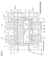
- Fig. 1 is a plan view of the surface mounting machine 1 according to Embodiment 1 of the present invention
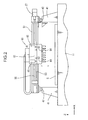
- Fig. 2 is a partial enlarged view showing the support structure of the head unit.
- the surface mounting machine 1 includes a surface mounting machine body 10 and a feeder 150.
- the surface mounting machine body 10 includes a base 11 having a smooth top face, and is configured by various devices being disposed on the base 11.
- a feeder 150 (parts feeding device) for feeding parts is equipped in the surface mounting machine body 10.
- the longitudinal direction (horizontal direction of Fig. 1 ) of the base 11 is referred to as the X direction
- the depth direction (vertical direction of Fig. 1 ) of the base 11 is referred to as the Y direction
- the vertical direction of Fig. 2 is referred to as the Z direction.
- a transfer conveyer (hereinafter also simply referred to as a "conveyer") 20 for transferring a printed circuit board is disposed at the center of the base 11.
- the transfer conveyer 20 includes a pair of transfer belts 21 that is circularly driven in the X direction.
- the printed circuit board G is set to be installed across both transfer belts 21, the printed circuit board G on the top face of the belt is delivered in the drive direction of the transfer belts 21 due to the friction with the transfer belts 21.
- the right side shown in Fig. 1 is the entry to the surface mounting machine 1, and the printed circuit board G is introduced into the surface mounting machine 1 through the conveyer 20 from the right side shown in Fig. 1 .
- the introduced printed circuit board G is carried by the conveyer 20 to the work location (position shown with the dashed-two dotted line in Fig. 1 ) at the center of the base 11, and stops there.
- the parts feeding unit 15 is provided at four places around the work location. Each parts feeding unit 15 is provided with a feeder mount board 140. A plurality of feeders 150 is horizontally mounted on each feeder mount board 140.
- the surface mounting machine 1 additionally includes a parts loading device 30.
- the parts loading device 30 performs the mounting process of mounting, at the work location, the parts W fed through the feeder 150 on the printed circuit board G. After the mounting process is completed, the printed circuit board G is carried in the left direction of Fig. 1 through the conveyer 20, and carried outside the machine.
- the parts loading device 30 generally includes an X axis servo mechanism, a Y axis servo mechanism, a Z axis servo mechanism, and a mounting head 63 that is driven in the X axis, Y axis, and Z axis directions by the foregoing servo mechanisms.
- the surface mounting machine 1 includes a pair of supporting legs 41, a guide rail 42 and a head support 51 for the parts loading device 30.
- the pair of supporting legs 41 is arranged on the base 11. Both supporting legs 41 are positioned on either side of the work location, and both extend linearly in the Y direction.
- the guide rail 42 is placed on the top face of the respective supporting legs 41, and extends in the Y direction.
- the head support 51 is mounted on the pair of supporting legs 41 as a result of the bottom face of the end thereof in the longitudinal direction being fitted with the left and right guide rails 42.
- a Y axis ball screw 45 extending in the Y direction is attached to the right-side supporting leg 41, and a ball nut (not shown) is additionally threadably mounted on the Y axis ball screw 45.
- a Y axis motor 47 is attached along the Y axis ball screw 45.
- a guide member 53 extending in the X direction is provided to the head support 51.
- a head unit 60 is mounted on the guide member 53 in a manner of being freely movable along the axis of the guide member 53.
- An X axis ball screw 55 extending in the X direction is mounted on the head support 51, and a ball nut (not shown) is additionally threadably mounted on the X axis ball screw 55.
- An X axis motor 57 is attached along the X axis ball screw 55. When the X axis motor 57 is driven, as a result of the ball nut moving along the X axis ball screw 55, the head unit 60 fixed to the ball nut moves in the X direction along the guide member 53 (X axis servo mechanism).
- the head unit 60 can be operated to move in the horizontal direction (XY direction) on the base 11.
- the mounting head 63 explained below can be arbitrarily moved within the head motion space K (shown with a dashed line frame in Fig. 1 ) on the base 11.
- a plurality of mounting heads 63 for performing the mounting operation are loaded in the head unit 60 in sequence.
- the mounting head 63 is protruding downward from the bottom face of the head unit 60, and an adsorption nozzle 64 is provided to the front edge thereof.
- Each mounting head 63 can be rotated around the axis based on the drive of the R axis motor 49 ( Fig. 6 ), and lifted and lowered relative to the frame 61 of the head unit 60 based on the drive of the Z axis motor 48 ( Fig. 6 ) (Z axis servo mechanism).
- Negative pressure is supplied to each adsorption nozzle 64 from a negative pressure device not shown. It is thereby possible to generate suction at the front edge of the head 63.
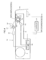
- the mounting head 63 can extract the parts W fed through the feeder 150 from the parts feeding position A ( Fig. 4 ) on the feeder 150 and mount such parts W on the printed circuit board G.
- the surface mounting machine 1 additionally includes a parts recognition camera 17 ( Fig. 1 ), and a printed board recognition camera 65 (corresponds to the "pullback detection unit" of the present invention).
- the parts recognition camera 17 captures an image of the parts W that were extracted by the mounting head 63, and detects the adsorption posture of the parts W.
- the printed board recognition camera 65 is fixed to the head unit 60 in a manner where the imaging face is facing downward, and moves integrally with the head unit 60. Consequently, as a result of driving the foregoing X axis servo mechanism and the Y axis servo mechanism, the image of an arbitrary position on the printed circuit board G in the work location can be captured by the printed board recognition camera 65.
- the parts feeding tape 145 which functions as a carrier for retaining the parts is foremost explained, and the configuration of the feeder 150 and the empty tape cutting device 170 will be subsequently explained.
- the parts feeding tape 145 is of a sheet shape extending in one direction, and includes hollow parts housing units 146a, which are opened upward, at regular intervals (that is, feed pitch of the parts W) Lo.
- An engagement hole 146b penetrating in the vertical direction is provided to one side of each parts feeding tape 145. These engagement holes 146b are arranged at regular intervals.
- Each parts housing unit 146a houses one part W such as an IC chip, and a cover tape 147 is attached to the top face of the parts feeding tape 145 so as to seal the parts housing units 146a.
- the parts feeding tape 145 is wound around a reel R ( Fig. 4 ), and one end thereof is unwound from the reel R.
- the feeder 150 includes a sprocket 153, a feed motor 155 (drive unit) for rotating the sprocket 153 and unwinding the parts feeding tape 145, a collection roller 163 for collecting the cover tape 147, a pullback motor 165 for rotating the collection roller 163, and a base part 151 to which the foregoing components are installed.
- the base part 151 is of an elongated shape in its longitudinal direction, and the reel R around which the parts feeding tape 145 is wound is fixed to the rear side thereof.
- the top face part of the base part 151 functions as the tape passage of the parts feeding tape 145 unwound from the reel R.
- the sprocket 153 is rotatably mounted to the front part of the base part 151.
- a drive gear 153A is integrally formed on the side face of the sprocket 153, and a motor gear on the side of the feed motor 155 engages with the drive gear 153A.
- Engagement teeth 154 are provided to the outer peripheral face of the sprocket 153 at even intervals. Each engagement tooth 154 engages with each engagement hole 146b of the parts feeding tape 145. Accordingly, when the feed motor 155 is powered and driven, the sprocket 153 rotates in the forward direction (rotation in the S direction shown in Fig. 4 ), and transfers the parts feeding tape 145 toward the parts feeding position A set at the front part of the feeder 150. Specifically, the feed motor 155 pitch-feeds the parts feeding tape 145 based on the feed pitch Lo of the parts W.
- the cover tape 147 is peeled backward from the parts feeding table 145 in front of the parts feeding position A, and collected by the collection roller 163. After the cover tape 147 is peeled, since the parts W housed in the parts housing unit 146a become exposed, the parts W can be extracted by the mounting head 63 at the parts feeding position A.
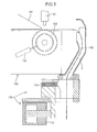
- the empty parts feeding tape 145 from which the parts W were extracted passes through a chute S provided to the parts feeding unit 15 and is guided to the lower front part of the feeder 150 as shown in Fig. 5 .
- an empty tape cutting device 170 is mounted at the exit of the chute S.
- the empty tape cutting device 170 includes a cutting blade 171 mounted at the chute exit, and a drive unit (cylinder) 175.
- the cutting blade 171 is fixed to the front part of the top face of the movable plate 173.
- the cylinder 175 When the cylinder 175 is operated, the movable plate 173 reciprocates in the horizontal direction. Accordingly, the parts feeding tape 145 protruding downward from the exit of the chute S can be cut with the cutting blade 171.
- the empty tape is cut by the cutting blade 171 when the total length of the empty tape P exceeds a cut value Lk (refer to Fig. 8 ).
- the controller 210 governs the control of the overall surface mounting machine body 10.
- the controller 210 functionally includes a mounting program storage unit 212, a transfer system data storage unit 213, a motor control unit 215, an image processing unit 216, a storage unit 217 and an I/O unit 218.
- An operation panel 220 is connected to the arithmetic processing unit 211. and various input operations are enabled via the operation panel 220.
- the mounting program storage unit 212 stores a mounting program for controlling the servo mechanism configured from an X axis motor 57, a Y axis motor 47, a Z axis motor 48, an R axis motor 49, and so on.
- the transfer system data storage unit 213 stores data for controlling a transfer system such as the transfer conveyer 20.
- the motor control unit 215 drives the various motors together with the arithmetic processing unit 211 according to the mounting program. Various motors are electrically connected to the motor control unit 215.
- the parts recognition camera 17 and the printed board recognition camera 65 are electrically connected to the image processing unit 216, and the imaging signals output from the respective cameras 17, 65 are respectively loaded.
- the image processing unit 216 analyzes the parts image and analyzes the printed board image based on the loaded imaging signals.
- the storage unit 217 stores the mounting program, and the data required for executing the empty tape recovery sequence described later.
- the I/O unit 218 is a so-called interface, and is used for sending and receiving control signals to and from the feeder 150, as well as for loading the detection signals output from the various sensors provided to the surface mounting machine body 10.
- the empty tape cutting device 170 is connected to the I/O unit 218, and the cutting of the empty tape P by the empty tape cutting device 170 is carried out based on commands from the arithmetic processing unit 211 provided to the controller 210.
- the feeder 150 includes a feeder control unit (corresponds to the "control unit” of the present invention) 250, a feed motor 155, a pullback motor 165, a storage unit 260 and an I/O unit 270.
- the feeder control unit 250 includes a feed operation execution unit 251, a detection unit 253, a determination unit 255 and a rewind execution unit 257 (pullback execution unit).
- the feed operation execution unit 251 executes the pitch-feeding operation (operation of unwinding the parts feeding tape) of the parts W toward the parts feeding position A by coordinating with the arithmetic processing unit 211 of the mounting machine body 10 and controlling the rotation and stop of the feed motor 155 and the pullback motor 165.
- the detection unit 253, the determination unit 255, and the rewind execution unit 257 are provided for performing the recovery of the empty tape P explained next.
- the detection unit 253 fulfills the function for detection of executing the work for removing the feeder 150 from the surface mounting machine body 10.
- the determination unit 255 fulfills the function of determining the length Lp of the empty tape P.
- the rewind execution unit 257 fulfils the function of executing the process of rewinding the empty tape P in the amount of the determined length Lp when the execution of the work for removing the feeder 150 is detected.
- the storage unit 260 is configured from a non-volatile memory such as EEPROM or NVRAM.
- the I/O unit 270 is a so-called interface, and is connected, via a signal wire, with the I/O unit 218 provided to the mounting machine body 10.
- the process (pullback process) of rewinding the parts feeding tape (empty tape) P that has become empty as a result of feeding the parts is executed.
- the empty tape P hanging downward from the front of the base part 151 is rewound backward to achieve a state where the empty tape P is not hanging; that is, the front edge (f) of the empty tape P is caused to basically coincide with the front edge of the base part 151 (refer to Fig. 7B ).
- the empty tape P hanging downward from the front of the base part 151 is rewound backward to achieve a state where the empty tape P is not hanging; that is, the front edge (f) of the empty tape P is caused to basically coincide with the front edge of the base part 151 (refer to Fig. 7B ).
- the length Lp of the empty tape P is now explained.
- the empty tape P arises as a result of feeding the parts W.
- the length "Lp" of the empty tape P can be calculated with the following Formula (1) when the number of parts W that have been fed is "N" and the feed pitch of the parts W is "Lo (refer to Fig. 3 )".
- Lp N ⁇ Lo
- the controller 210 of the surface mounting machine body 10 manages the data regarding the number of parts W that have been fed and the data regarding the feed pitch of the parts W with respect to each feeder 150, and stores such data in the storage unit 217.
- the length Lp of the empty tape P of the removed feeder 150 is calculated by the arithmetic processing unit 211 (functional part which functions as the "determination unit” of the claims) of the surface mounting machine body 10 based on the foregoing Formula (1). This calculation result is notified to the feeder 150. The feeder 150 is thereby able to recognize the length Lp of the empty tape P.
- the front edge of the empty tape P is cut by the cutting blade 171 when the total length Lp of the empty tape P exceeds the cut value Lk.
- the total length Lp of the empty tape P becomes longer than the time of the foregoing tape cut in the length that the parts W have been fed.
- the total length "Lp" of the empty tape when a tape cut was performed can be calculated with the following Formula (2) when the total length of the empty tape P at the time of tape cut is "Lc", the number of parts W that have been fed after the tape cut is "M”, and the feed pitch of the parts W is "Lo".
- Lp Lc + M ⁇ Lo
- the controller 210 of the surface mounting machine body 10 also manages and stores data regarding the execution/non-execution of a tape cut, the total length Lc of the empty tape P at the time of tape cut, and the number of parts W that have been fed after the tape cut with respect to each feeder 150. Accordingly, when a tape cut is executed, the arithmetic processing unit 211 calculates the length Lp of the empty tape P based on the Formula (2).
- the removal work procedure of the feeder 150 is now explained with reference to Fig. 9 and Fig. 10 .
- the worker performs an operation of notifying the surface mounting machine body 10 of the removal work of the feeder 150 (S20).
- the operation panel 220 provided to the surface mounting machine body 10 accepts the input of the indication of intent to perform the removal work of the feeder 150 and the number of the feeder 150 to be removed.
- the notification of the removal work is communicated from the surface mounting machine body 10 to the feeder 150 to be removed, and received by the detection unit 253 of the feeder control unit 250.
- the detection unit 253 detects that the removal work of the feeder 150 from the surface mounting machine body 10 will be executed.
- the detection unit 253 When the detection unit 253 detects the execution of the removal work of the feeder 150, the detection unit 253 notifies the information thereof to the rewind execution unit 257. Consequently, the process of recovering the empty tape P of the feeder 150 to be removed is executed by the rewind execution unit 257 of the feeder 150 (S50).
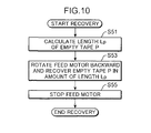
- the tape recovery process of S50 shown in Fig. 9 is configured from the three processing steps of S51 to S55 shown in Fig. 10 .
- the length of the empty tape P can be calculated so as long as information regarding the number of parts W that have been fed, the feed pitch Lo of the parts W, and the tape cut by the empty tape cutting device 170 is available. Accordingly, it is also possible to send the necessary data from the surface mounting machine body 10 to the feeder 150 and calculate the length of the empty tape P using the determination unit 255 of the feeder control unit 250. In the foregoing case, the length Lp of the empty tape will be notified from the determination unit 255 to the rewind execution unit 257.
- the rewind execution unit 257 of the feeder 150 acquires the data regarding the length Lp of the empty tape P
- the rewind execution unit 257 causes the feed motor 155 to rotate in the opposite direction (S53). Consequently, since the sprocket 153 will rotate in the opposite direction (R direction of Fig. 7 ), the empty tape P is wound around the sprocket 153, and recovered by the reel R (rewind process).
- the feeder control unit 250 rotates the feed motor 155 backward for the required number of rotations to recover the empty tape P in the amount of "Lp"
- the feeder control unit 250 stops the feed motor 155 (S55).
- the feeder 150 will achieve a state where the empty tape P is not hanging down; that is, a state where the front edge (f) of the empty tape P basically coincides with the front edge 151a of the base part 151 (refer to Fig. 7B ).
- the surface mounting machine body 10 displays a message allowing the removal of the designated feeder 150 on the display unit provided with the operation panel 220. For example, if the feeder 150 designated in S20 is "No. 3", character information to the effect of "No. 3 feeder may be removed” is displayed (S60).
- the empty tape P that has become empty as a result of feeding the parts is rewound, it is possible to restrict the empty tape P from extending to the head motion space K upon removing the feeder 150.
- the empty tape P will not become tangled with the mounting head 63 that is moving within the head motion space K.
- the length Lp of the empty tape P is obtained based on calculation, the number of parts can be reduced in comparison to cases of detecting whether or not the empty tape P has been rewound using a sensor or the like.
- the rewinding amount of the tape is preferably stored in the storage unit 260 of the feeder 150.
- the cue of the parts feeding tape 145 can be performed simply by feeding the tape in the rewinding amount.
- Embodiment 2 of the present invention is now explained with reference to Fig. 11 .
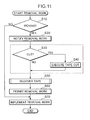
- the surface mounting machine of Embodiment 2 differs from Embodiment 1 in that the removal work procedure of the feeder 150 has been partially changed, and the processing steps of S30 and S40 shown in Fig. 11 have been newly added (encompassed by a dashed line in the diagram).
- the newly added processing steps of S30 and S40 are performed for cutting the empty tape P in advance (S30, S40) and thereafter recovering the empty tape P upon removing the feeder 150 while the surface mounting machine body 10 is operating.
- Whether to cut the empty tape P can be selected by the worker to perform the setting operation using the operation panel 220.
- the determination is YES in S30, and the cutting of the empty tape P by the empty tape cutting device 170 is subsequently executed in S40.
- the cutting of the empty tape P is executed, the length of the empty tape P becomes "Lc". Accordingly, in the foregoing case, there is no need to go through the trouble of calculating the total length of the empty tape P as in Embodiment 1, and it will suffice if the empty tape P is recovered in the amount of length "Lc" in the tape recovery process of S50.
- Embodiment 3 of the present invention is now explained with reference to Fig. 12 .
- the length of the empty tape P was calculated upon recovering the empty tape P (S51).
- the empty tape P is rewound at predetermined pitches, and whether or not the rewinding of the empty tape P is complete is recognized from the image taken by the printed board recognition camera (corresponds to the "pullback detection unit" of the present invention) 65 mounted on the head unit 60.
- the tape recovery process of S50 of Fig. 9 is configured from the processing steps of S151 to S159 shown in Fig. 12 .
- S151 the process of moving the printed board recognition camera 65 mounted on the head unit 60 to a position above the front end of the base part 151 of the feeder 150 to be removed is performed by the arithmetic processing unit 211.
- the feed motor 155 of the feeder 150 to be removed is rotated backward, and the process of rewinding the empty tape P at a predetermined pitch (for instance, 30 mm) is performed by the rewind execution unit 257 of the feeder control unit 250.
- the rewinding is paused (S155).
- the printed board recognition camera 65 standing by above the feeder captures an image of the front part of the base part 151 of the feeder 150 (S157).
- the processing of determining whether or not the captured image contains the front edge (f) of the empty tape P is performed by the arithmetic processing unit 211 (S159).
- the front edge (f) of the empty tape P is not included in the image; that is, when the rewinding of the empty tape P is still midway, the determination is NO in S159.
- the routine subsequently returns to S153, and the empty tape P is additionally rewound by a predetermined pitch.
- the printed board recognition camera 65 subsequently captures an image of the front part of the base part 151.
- the processing of determining whether or not the captured image contains the front edge (f) of the empty tape P is performed, and, when the front edge (f) of the empty tape P is not included in the captured image (S159), the routine once again returns to S153.
- the processing steps of S153 to S159 are repeatedly performed until the front edge (f) of the empty tape P is detected, and the empty tape P is rewound by a predetermined pitch at a time.
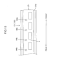
- the front edge (f) of the empty tape P will basically coincide with the front edge 151a of the base part 151 of the feeder 150, as shown in Fig. 13 , the front edge (f) of the empty tape P can be detected from the camera image.
- the determination is YES. Consequently, the repetition loop of S153 to S159 exited, and the recovery work is ended.
- the rewind process of the empty tape P is ended on the condition that the rewinding of the empty tape P up to the front edge thereof is detected in the image.
- Embodiment 3 since there is no need to go through the trouble of calculating the total length of the empty tape P as in Embodiment 1, the burden of the arithmetic processing unit 211 of the surface mounting machine body 10 can be alleviated. Moreover, in Embodiment 3, since the front edge (f) of the empty tape P is recognized by using the printed board recognition camera 65, there is an advantage in that the number of parts can be reduced in comparison to cases of recognizing the front edge (f) of the empty tape P by using a dedicated sensor or the like. Moreover, since the rewinding is ended upon detecting the front edge (f) of the empty tape P, the empty tape P can be reliably recovered.
- the parts feeding device is a parts feeding device equipped in a surface mounting machine body including a drive unit for feeding a parts feeding tape which houses parts, and a control unit for controlling the drive unit.
- the control unit includes a detection unit for detecting execution of work for removing the parts feeding device from the surface mounting machine body, and a pullback execution unit for causing the drive unit to execute a process of pulling back the parts feeding tape, which has become empty as a result of feeding the parts, when the execution of work for removing the parts feeding device is detected by the detection unit.
- the parts feeding tape is wound around a reel
- the drive unit is a feed motor
- the pullback execution unit is a rewind execution unit for causing the drive unit to execute a process of rewinding the empty parts feeding tape.
- the feeding and pullback of the parts feeding tape can be executed easily based on the unwinding and rewinding of the parts feeding tape from the reel.
- the control unit includes a determination unit for determining a length of an empty portion of the tape, which has become empty as a result of feeding the parts, from data regarding a feed pitch of the parts and the number of parts that have been fed, and the rewind execution unit rewinds the parts feeding tape in an amount of the determined length.
- the rewind execution unit rewinds the parts feeding tape, which has become empty as a result of feeding the parts, by rotating the feed motor backward.
- the empty tape is rewound using a feed motor, the number of parts can be reduced in comparison to cases of providing a dedicated motor for the rewinding process.
- the surface mounting machine includes a parts feeding device for feeding parts, and a surface mounting machine body to which the parts feeding device is equipped, and which receives the feeding of parts from the parts feeding device to thereby mount the parts on a printed circuit board.
- the parts feeding device includes a drive unit for feeding a parts feeding tape which houses parts, and a control unit for controlling the drive unit.
- the control unit includes a detection unit for detecting execution of work for removing the parts feeding device from the surface mounting machine body, and a pullback execution unit for causing the drive unit to execute a process of pulling back the parts feeding tape, which has become empty as a result of feeding the parts, when the execution of work for removing the parts feeding device is detected by the detection unit.
- the surface mounting machine further includes a pullback detection unit for detecting whether or not the parts feeding tape, which has become empty as a result of feeding the parts, has been rewound such that a front edge thereof returns to a front end of the parts feeding device, and the rewind execution unit ends the process of rewinding the parts feeding tape on the condition that the rewinding of the parts feeding tape up to the front edge thereof is detected by the pullback detection unit.
- the empty tape can be reliably recovered since the rewinding process is ended by detecting the front edge of the empty tape.
- protrusion of the empty tape relative to the motion space of the mounting head can be restricted.
- the empty tape will not become tangled with the mounting head.
Landscapes
- Engineering & Computer Science (AREA)
- Manufacturing & Machinery (AREA)
- Microelectronics & Electronic Packaging (AREA)
- Mechanical Engineering (AREA)
- Supply And Installment Of Electrical Components (AREA)
Applications Claiming Priority (1)
| Application Number | Priority Date | Filing Date | Title |
|---|---|---|---|
| JP2012130872A JP5872969B2 (ja) | 2012-06-08 | 2012-06-08 | 部品供給装置及び表面実装機 |
Publications (3)
| Publication Number | Publication Date |
|---|---|
| EP2672800A2 true EP2672800A2 (fr) | 2013-12-11 |
| EP2672800A3 EP2672800A3 (fr) | 2017-02-15 |
| EP2672800B1 EP2672800B1 (fr) | 2019-07-10 |
Family
ID=48139677
Family Applications (1)
| Application Number | Title | Priority Date | Filing Date |
|---|---|---|---|
| EP13001802.1A Active EP2672800B1 (fr) | 2012-06-08 | 2013-04-08 | Dispositif d'alimentation en pièces et machine de montage en surface |
Country Status (5)
| Country | Link |
|---|---|
| US (1) | US9326434B2 (fr) |
| EP (1) | EP2672800B1 (fr) |
| JP (1) | JP5872969B2 (fr) |
| KR (1) | KR101647653B1 (fr) |
| CN (1) | CN103491759B (fr) |
Cited By (3)
| Publication number | Priority date | Publication date | Assignee | Title |
|---|---|---|---|---|
| EP3554205A4 (fr) * | 2016-12-12 | 2019-12-25 | Fuji Corporation | Système de réglage de distributeur à bande |
| EP3806606A4 (fr) * | 2018-05-31 | 2021-06-16 | Fuji Corporation | Distributeur et dispositif de montage d'éléments |
| EP4030882A4 (fr) * | 2019-09-13 | 2022-09-21 | Fuji Corporation | Dispositif d'alimentation et machine de montage de composants |
Families Citing this family (13)
| Publication number | Priority date | Publication date | Assignee | Title |
|---|---|---|---|---|
| WO2016139713A1 (fr) * | 2015-03-02 | 2016-09-09 | 富士機械製造株式会社 | Dispositif de commande d'apport, procédé de commande et dispositif de montage de composant |
| US11019760B2 (en) * | 2016-06-13 | 2021-05-25 | Fuji Corporation | Feeder management method and feeder management device |
| JP6745885B2 (ja) * | 2016-09-08 | 2020-08-26 | 株式会社Fuji | 部品実装機 |
| JP7460307B2 (ja) * | 2016-12-12 | 2024-04-02 | 株式会社Fuji | テープフィーダ段取システム |
| EP3742878B1 (fr) * | 2018-01-19 | 2024-04-03 | Fuji Corporation | Dispositif de stockage et procédé de stockage de bobine |
| CN113056966B (zh) * | 2018-11-20 | 2023-02-28 | 雅马哈发动机株式会社 | 部件补给系统及部件补给方法 |
| JP7260679B2 (ja) * | 2020-01-28 | 2023-04-18 | 株式会社Fuji | 部品実装機およびフィーダ |
| CN111702480A (zh) * | 2020-06-07 | 2020-09-25 | 赣州智晟知识产权咨询服务有限公司 | 一种用于液晶显示屏多组同步定位装配机构 |
| JP7466411B2 (ja) * | 2020-09-03 | 2024-04-12 | 株式会社Fuji | 部品供給フィーダ及びそれを備える部品実装機 |
| TWI851991B (zh) * | 2021-06-01 | 2024-08-11 | 群創光電股份有限公司 | 電子裝置的製造方法 |
| JP7611396B2 (ja) * | 2021-07-29 | 2025-01-09 | 株式会社Fuji | 部品装着機 |
| CN118402326A (zh) * | 2022-01-31 | 2024-07-26 | 株式会社富士 | 带自动处理装置及带盘装填装置 |
| WO2025234038A1 (fr) * | 2024-05-08 | 2025-11-13 | 株式会社Fuji | Système de retrait de bande |
Citations (1)
| Publication number | Priority date | Publication date | Assignee | Title |
|---|---|---|---|---|
| JP2009295829A (ja) | 2008-06-06 | 2009-12-17 | Juki Corp | 部品供給装置 |
Family Cites Families (12)
| Publication number | Priority date | Publication date | Assignee | Title |
|---|---|---|---|---|
| JP2765187B2 (ja) | 1990-05-28 | 1998-06-11 | ソニー株式会社 | 電子部品装着装置 |
| JP3444034B2 (ja) * | 1995-08-01 | 2003-09-08 | 松下電器産業株式会社 | 電子部品供給装置 |
| JP3809251B2 (ja) * | 1997-07-09 | 2006-08-16 | 富士機械製造株式会社 | 回路部品供給方法および供給システム |
| JP3329304B2 (ja) * | 1999-03-11 | 2002-09-30 | 日本電気株式会社 | チップ部品供給装置 |
| JP4733281B2 (ja) * | 2001-03-06 | 2011-07-27 | 富士機械製造株式会社 | 対フィーダ作業支援装置 |
| JP2003258493A (ja) * | 2001-12-28 | 2003-09-12 | Fuji Mach Mfg Co Ltd | 電気部品供給方法および電気部品装着システム |
| CN101507382B (zh) | 2006-08-23 | 2012-04-04 | 雅马哈发动机株式会社 | 带式送料器、安装机 |
| JP2008053381A (ja) * | 2006-08-23 | 2008-03-06 | Yamaha Motor Co Ltd | テープフィーダおよび実装機 |
| US7850040B2 (en) * | 2006-10-23 | 2010-12-14 | Hover-Davis, Inc. | Component tape feeder |
| JP5280658B2 (ja) * | 2007-09-06 | 2013-09-04 | Juki株式会社 | 部品実装装置 |
| JP2009238821A (ja) * | 2008-03-26 | 2009-10-15 | Hitachi High-Tech Instruments Co Ltd | 電子部品装着装置 |
| JP5410337B2 (ja) * | 2010-03-03 | 2014-02-05 | 株式会社日立ハイテクインスツルメンツ | フィーダ、供給テープの移動制御方法または電子部品装着装置 |
-
2012
- 2012-06-08 JP JP2012130872A patent/JP5872969B2/ja active Active
-
2013
- 2013-03-13 US US13/802,346 patent/US9326434B2/en active Active
- 2013-03-21 CN CN201310091614.0A patent/CN103491759B/zh active Active
- 2013-04-08 EP EP13001802.1A patent/EP2672800B1/fr active Active
- 2013-04-10 KR KR1020130039135A patent/KR101647653B1/ko active Active
Patent Citations (1)
| Publication number | Priority date | Publication date | Assignee | Title |
|---|---|---|---|---|
| JP2009295829A (ja) | 2008-06-06 | 2009-12-17 | Juki Corp | 部品供給装置 |
Cited By (4)
| Publication number | Priority date | Publication date | Assignee | Title |
|---|---|---|---|---|
| EP3554205A4 (fr) * | 2016-12-12 | 2019-12-25 | Fuji Corporation | Système de réglage de distributeur à bande |
| EP3806606A4 (fr) * | 2018-05-31 | 2021-06-16 | Fuji Corporation | Distributeur et dispositif de montage d'éléments |
| EP4030882A4 (fr) * | 2019-09-13 | 2022-09-21 | Fuji Corporation | Dispositif d'alimentation et machine de montage de composants |
| US11889632B2 (en) | 2019-09-13 | 2024-01-30 | Fuji Corporation | Feeder and component mounting machine |
Also Published As
| Publication number | Publication date |
|---|---|
| JP5872969B2 (ja) | 2016-03-01 |
| KR101647653B1 (ko) | 2016-08-11 |
| CN103491759B (zh) | 2016-12-28 |
| KR20130138094A (ko) | 2013-12-18 |
| EP2672800B1 (fr) | 2019-07-10 |
| US9326434B2 (en) | 2016-04-26 |
| JP2013254895A (ja) | 2013-12-19 |
| EP2672800A3 (fr) | 2017-02-15 |
| US20130326867A1 (en) | 2013-12-12 |
| CN103491759A (zh) | 2014-01-01 |
Similar Documents
| Publication | Publication Date | Title |
|---|---|---|
| US9326434B2 (en) | Parts feeding device and surface mounting machine | |
| JP5985275B2 (ja) | フィーダ制御方法及び電子部品装着装置 | |
| JP4450772B2 (ja) | 電子部品装着装置 | |
| CN108040457B (zh) | 供料器及供料器控制方法以及电子元件安装装置 | |
| US8099860B2 (en) | Electronic component mounting apparatus | |
| EP1793660B1 (fr) | Appareil de montage de composant électronique | |
| JP6173777B2 (ja) | サプレッサ、フィーダ、フィーダ制御方法及び電子部品装着装置 | |
| JP2014011315A (ja) | フィーダ及びフィーダ制御方法並びに電子部品装着装置 | |
| JP6916390B2 (ja) | フィーダおよび部品実装機 | |
| JP4917586B2 (ja) | 電子部品装着装置 | |
| JP6082280B2 (ja) | 電子部品供給ユニット及び電子部品装着装置 | |
| JP6440812B2 (ja) | 電子部品装着装置及び電子部品装着方法 | |
| JP6307123B2 (ja) | フィーダ及びフィーダ制御方法 | |
| JP4887067B2 (ja) | 電子部品装着装置 | |
| JP7829164B2 (ja) | 部品装着装置及び部品供給方法 | |
| JP2014123636A (ja) | 電子部品装着装置 | |
| JP4460071B2 (ja) | 電子部品装着装置 |
Legal Events
| Date | Code | Title | Description |
|---|---|---|---|
| PUAI | Public reference made under article 153(3) epc to a published international application that has entered the european phase |
Free format text: ORIGINAL CODE: 0009012 |
|
| AK | Designated contracting states |
Kind code of ref document: A2 Designated state(s): AL AT BE BG CH CY CZ DE DK EE ES FI FR GB GR HR HU IE IS IT LI LT LU LV MC MK MT NL NO PL PT RO RS SE SI SK SM TR |
|
| AX | Request for extension of the european patent |
Extension state: BA ME |
|
| PUAL | Search report despatched |
Free format text: ORIGINAL CODE: 0009013 |
|
| AK | Designated contracting states |
Kind code of ref document: A3 Designated state(s): AL AT BE BG CH CY CZ DE DK EE ES FI FR GB GR HR HU IE IS IT LI LT LU LV MC MK MT NL NO PL PT RO RS SE SI SK SM TR |
|
| AX | Request for extension of the european patent |
Extension state: BA ME |
|
| RIC1 | Information provided on ipc code assigned before grant |
Ipc: H05K 13/04 20060101AFI20170111BHEP |
|
| RAP1 | Party data changed (applicant data changed or rights of an application transferred) |
Owner name: YAMAHA HATSUDOKI KABUSHIKI KAISHA |
|
| STAA | Information on the status of an ep patent application or granted ep patent |
Free format text: STATUS: REQUEST FOR EXAMINATION WAS MADE |
|
| 17P | Request for examination filed |
Effective date: 20170811 |
|
| RBV | Designated contracting states (corrected) |
Designated state(s): AL AT BE BG CH CY CZ DE DK EE ES FI FR GB GR HR HU IE IS IT LI LT LU LV MC MK MT NL NO PL PT RO RS SE SI SK SM TR |
|
| GRAP | Despatch of communication of intention to grant a patent |
Free format text: ORIGINAL CODE: EPIDOSNIGR1 |
|
| STAA | Information on the status of an ep patent application or granted ep patent |
Free format text: STATUS: GRANT OF PATENT IS INTENDED |
|
| INTG | Intention to grant announced |
Effective date: 20190227 |
|
| GRAS | Grant fee paid |
Free format text: ORIGINAL CODE: EPIDOSNIGR3 |
|
| GRAA | (expected) grant |
Free format text: ORIGINAL CODE: 0009210 |
|
| STAA | Information on the status of an ep patent application or granted ep patent |
Free format text: STATUS: THE PATENT HAS BEEN GRANTED |
|
| AK | Designated contracting states |
Kind code of ref document: B1 Designated state(s): AL AT BE BG CH CY CZ DE DK EE ES FI FR GB GR HR HU IE IS IT LI LT LU LV MC MK MT NL NO PL PT RO RS SE SI SK SM TR |
|
| REG | Reference to a national code |
Ref country code: GB Ref legal event code: FG4D |
|
| REG | Reference to a national code |
Ref country code: CH Ref legal event code: EP Ref country code: AT Ref legal event code: REF Ref document number: 1154956 Country of ref document: AT Kind code of ref document: T Effective date: 20190715 |
|
| REG | Reference to a national code |
Ref country code: IE Ref legal event code: FG4D |
|
| REG | Reference to a national code |
Ref country code: DE Ref legal event code: R096 Ref document number: 602013057554 Country of ref document: DE |
|
| REG | Reference to a national code |
Ref country code: NL Ref legal event code: MP Effective date: 20190710 |
|
| REG | Reference to a national code |
Ref country code: LT Ref legal event code: MG4D |
|
| REG | Reference to a national code |
Ref country code: AT Ref legal event code: MK05 Ref document number: 1154956 Country of ref document: AT Kind code of ref document: T Effective date: 20190710 |
|
| PG25 | Lapsed in a contracting state [announced via postgrant information from national office to epo] |
Ref country code: HR Free format text: LAPSE BECAUSE OF FAILURE TO SUBMIT A TRANSLATION OF THE DESCRIPTION OR TO PAY THE FEE WITHIN THE PRESCRIBED TIME-LIMIT Effective date: 20190710 Ref country code: AT Free format text: LAPSE BECAUSE OF FAILURE TO SUBMIT A TRANSLATION OF THE DESCRIPTION OR TO PAY THE FEE WITHIN THE PRESCRIBED TIME-LIMIT Effective date: 20190710 Ref country code: SE Free format text: LAPSE BECAUSE OF FAILURE TO SUBMIT A TRANSLATION OF THE DESCRIPTION OR TO PAY THE FEE WITHIN THE PRESCRIBED TIME-LIMIT Effective date: 20190710 Ref country code: NO Free format text: LAPSE BECAUSE OF FAILURE TO SUBMIT A TRANSLATION OF THE DESCRIPTION OR TO PAY THE FEE WITHIN THE PRESCRIBED TIME-LIMIT Effective date: 20191010 Ref country code: FI Free format text: LAPSE BECAUSE OF FAILURE TO SUBMIT A TRANSLATION OF THE DESCRIPTION OR TO PAY THE FEE WITHIN THE PRESCRIBED TIME-LIMIT Effective date: 20190710 Ref country code: NL Free format text: LAPSE BECAUSE OF FAILURE TO SUBMIT A TRANSLATION OF THE DESCRIPTION OR TO PAY THE FEE WITHIN THE PRESCRIBED TIME-LIMIT Effective date: 20190710 Ref country code: BG Free format text: LAPSE BECAUSE OF FAILURE TO SUBMIT A TRANSLATION OF THE DESCRIPTION OR TO PAY THE FEE WITHIN THE PRESCRIBED TIME-LIMIT Effective date: 20191010 Ref country code: PT Free format text: LAPSE BECAUSE OF FAILURE TO SUBMIT A TRANSLATION OF THE DESCRIPTION OR TO PAY THE FEE WITHIN THE PRESCRIBED TIME-LIMIT Effective date: 20191111 Ref country code: LT Free format text: LAPSE BECAUSE OF FAILURE TO SUBMIT A TRANSLATION OF THE DESCRIPTION OR TO PAY THE FEE WITHIN THE PRESCRIBED TIME-LIMIT Effective date: 20190710 |
|
| PG25 | Lapsed in a contracting state [announced via postgrant information from national office to epo] |
Ref country code: IS Free format text: LAPSE BECAUSE OF FAILURE TO SUBMIT A TRANSLATION OF THE DESCRIPTION OR TO PAY THE FEE WITHIN THE PRESCRIBED TIME-LIMIT Effective date: 20191110 Ref country code: RS Free format text: LAPSE BECAUSE OF FAILURE TO SUBMIT A TRANSLATION OF THE DESCRIPTION OR TO PAY THE FEE WITHIN THE PRESCRIBED TIME-LIMIT Effective date: 20190710 Ref country code: GR Free format text: LAPSE BECAUSE OF FAILURE TO SUBMIT A TRANSLATION OF THE DESCRIPTION OR TO PAY THE FEE WITHIN THE PRESCRIBED TIME-LIMIT Effective date: 20191011 Ref country code: AL Free format text: LAPSE BECAUSE OF FAILURE TO SUBMIT A TRANSLATION OF THE DESCRIPTION OR TO PAY THE FEE WITHIN THE PRESCRIBED TIME-LIMIT Effective date: 20190710 Ref country code: LV Free format text: LAPSE BECAUSE OF FAILURE TO SUBMIT A TRANSLATION OF THE DESCRIPTION OR TO PAY THE FEE WITHIN THE PRESCRIBED TIME-LIMIT Effective date: 20190710 Ref country code: ES Free format text: LAPSE BECAUSE OF FAILURE TO SUBMIT A TRANSLATION OF THE DESCRIPTION OR TO PAY THE FEE WITHIN THE PRESCRIBED TIME-LIMIT Effective date: 20190710 |
|
| PG25 | Lapsed in a contracting state [announced via postgrant information from national office to epo] |
Ref country code: TR Free format text: LAPSE BECAUSE OF FAILURE TO SUBMIT A TRANSLATION OF THE DESCRIPTION OR TO PAY THE FEE WITHIN THE PRESCRIBED TIME-LIMIT Effective date: 20190710 |
|
| PG25 | Lapsed in a contracting state [announced via postgrant information from national office to epo] |
Ref country code: DK Free format text: LAPSE BECAUSE OF FAILURE TO SUBMIT A TRANSLATION OF THE DESCRIPTION OR TO PAY THE FEE WITHIN THE PRESCRIBED TIME-LIMIT Effective date: 20190710 Ref country code: PL Free format text: LAPSE BECAUSE OF FAILURE TO SUBMIT A TRANSLATION OF THE DESCRIPTION OR TO PAY THE FEE WITHIN THE PRESCRIBED TIME-LIMIT Effective date: 20190710 Ref country code: RO Free format text: LAPSE BECAUSE OF FAILURE TO SUBMIT A TRANSLATION OF THE DESCRIPTION OR TO PAY THE FEE WITHIN THE PRESCRIBED TIME-LIMIT Effective date: 20190710 Ref country code: IT Free format text: LAPSE BECAUSE OF FAILURE TO SUBMIT A TRANSLATION OF THE DESCRIPTION OR TO PAY THE FEE WITHIN THE PRESCRIBED TIME-LIMIT Effective date: 20190710 Ref country code: EE Free format text: LAPSE BECAUSE OF FAILURE TO SUBMIT A TRANSLATION OF THE DESCRIPTION OR TO PAY THE FEE WITHIN THE PRESCRIBED TIME-LIMIT Effective date: 20190710 |
|
| PG25 | Lapsed in a contracting state [announced via postgrant information from national office to epo] |
Ref country code: SM Free format text: LAPSE BECAUSE OF FAILURE TO SUBMIT A TRANSLATION OF THE DESCRIPTION OR TO PAY THE FEE WITHIN THE PRESCRIBED TIME-LIMIT Effective date: 20190710 Ref country code: IS Free format text: LAPSE BECAUSE OF FAILURE TO SUBMIT A TRANSLATION OF THE DESCRIPTION OR TO PAY THE FEE WITHIN THE PRESCRIBED TIME-LIMIT Effective date: 20200224 Ref country code: CZ Free format text: LAPSE BECAUSE OF FAILURE TO SUBMIT A TRANSLATION OF THE DESCRIPTION OR TO PAY THE FEE WITHIN THE PRESCRIBED TIME-LIMIT Effective date: 20190710 Ref country code: SK Free format text: LAPSE BECAUSE OF FAILURE TO SUBMIT A TRANSLATION OF THE DESCRIPTION OR TO PAY THE FEE WITHIN THE PRESCRIBED TIME-LIMIT Effective date: 20190710 |
|
| REG | Reference to a national code |
Ref country code: DE Ref legal event code: R097 Ref document number: 602013057554 Country of ref document: DE |
|
| PLBE | No opposition filed within time limit |
Free format text: ORIGINAL CODE: 0009261 |
|
| STAA | Information on the status of an ep patent application or granted ep patent |
Free format text: STATUS: NO OPPOSITION FILED WITHIN TIME LIMIT |
|
| PG2D | Information on lapse in contracting state deleted |
Ref country code: IS |
|
| 26N | No opposition filed |
Effective date: 20200603 |
|
| PG25 | Lapsed in a contracting state [announced via postgrant information from national office to epo] |
Ref country code: SI Free format text: LAPSE BECAUSE OF FAILURE TO SUBMIT A TRANSLATION OF THE DESCRIPTION OR TO PAY THE FEE WITHIN THE PRESCRIBED TIME-LIMIT Effective date: 20190710 |
|
| PG25 | Lapsed in a contracting state [announced via postgrant information from national office to epo] |
Ref country code: MC Free format text: LAPSE BECAUSE OF FAILURE TO SUBMIT A TRANSLATION OF THE DESCRIPTION OR TO PAY THE FEE WITHIN THE PRESCRIBED TIME-LIMIT Effective date: 20190710 |
|
| REG | Reference to a national code |
Ref country code: CH Ref legal event code: PL |
|
| PG25 | Lapsed in a contracting state [announced via postgrant information from national office to epo] |
Ref country code: CH Free format text: LAPSE BECAUSE OF NON-PAYMENT OF DUE FEES Effective date: 20200430 Ref country code: LI Free format text: LAPSE BECAUSE OF NON-PAYMENT OF DUE FEES Effective date: 20200430 Ref country code: LU Free format text: LAPSE BECAUSE OF NON-PAYMENT OF DUE FEES Effective date: 20200408 Ref country code: FR Free format text: LAPSE BECAUSE OF NON-PAYMENT OF DUE FEES Effective date: 20200430 |
|
| REG | Reference to a national code |
Ref country code: BE Ref legal event code: MM Effective date: 20200430 |
|
| PG25 | Lapsed in a contracting state [announced via postgrant information from national office to epo] |
Ref country code: BE Free format text: LAPSE BECAUSE OF NON-PAYMENT OF DUE FEES Effective date: 20200430 |
|
| GBPC | Gb: european patent ceased through non-payment of renewal fee |
Effective date: 20200408 |
|
| PG25 | Lapsed in a contracting state [announced via postgrant information from national office to epo] |
Ref country code: IE Free format text: LAPSE BECAUSE OF NON-PAYMENT OF DUE FEES Effective date: 20200408 Ref country code: GB Free format text: LAPSE BECAUSE OF NON-PAYMENT OF DUE FEES Effective date: 20200408 |
|
| PG25 | Lapsed in a contracting state [announced via postgrant information from national office to epo] |
Ref country code: MT Free format text: LAPSE BECAUSE OF FAILURE TO SUBMIT A TRANSLATION OF THE DESCRIPTION OR TO PAY THE FEE WITHIN THE PRESCRIBED TIME-LIMIT Effective date: 20190710 Ref country code: CY Free format text: LAPSE BECAUSE OF FAILURE TO SUBMIT A TRANSLATION OF THE DESCRIPTION OR TO PAY THE FEE WITHIN THE PRESCRIBED TIME-LIMIT Effective date: 20190710 |
|
| PG25 | Lapsed in a contracting state [announced via postgrant information from national office to epo] |
Ref country code: MK Free format text: LAPSE BECAUSE OF FAILURE TO SUBMIT A TRANSLATION OF THE DESCRIPTION OR TO PAY THE FEE WITHIN THE PRESCRIBED TIME-LIMIT Effective date: 20190710 |
|
| PGFP | Annual fee paid to national office [announced via postgrant information from national office to epo] |
Ref country code: DE Payment date: 20250422 Year of fee payment: 13 |