EP2673097B1 - Laminoir à chaud pour fil machine et d'autres produits semblables - Google Patents
Laminoir à chaud pour fil machine et d'autres produits semblables Download PDFInfo
- Publication number
- EP2673097B1 EP2673097B1 EP12710322.4A EP12710322A EP2673097B1 EP 2673097 B1 EP2673097 B1 EP 2673097B1 EP 12710322 A EP12710322 A EP 12710322A EP 2673097 B1 EP2673097 B1 EP 2673097B1
- Authority
- EP
- European Patent Office
- Prior art keywords
- rolling
- unit
- hot
- gear reduction
- mechanical gear
- Prior art date
- Legal status (The legal status is an assumption and is not a legal conclusion. Google has not performed a legal analysis and makes no representation as to the accuracy of the status listed.)
- Active
Links
Images
Classifications
-
- B—PERFORMING OPERATIONS; TRANSPORTING
- B21—MECHANICAL METAL-WORKING WITHOUT ESSENTIALLY REMOVING MATERIAL; PUNCHING METAL
- B21B—ROLLING OF METAL
- B21B1/00—Metal-rolling methods or mills for making semi-finished products of solid or profiled cross-section; Sequence of operations in milling trains; Layout of rolling-mill plant, e.g. grouping of stands; Succession of passes or of sectional pass alternations
- B21B1/16—Metal-rolling methods or mills for making semi-finished products of solid or profiled cross-section; Sequence of operations in milling trains; Layout of rolling-mill plant, e.g. grouping of stands; Succession of passes or of sectional pass alternations for rolling wire rods, bars, merchant bars, rounds wire or material of like small cross-section
- B21B1/18—Metal-rolling methods or mills for making semi-finished products of solid or profiled cross-section; Sequence of operations in milling trains; Layout of rolling-mill plant, e.g. grouping of stands; Succession of passes or of sectional pass alternations for rolling wire rods, bars, merchant bars, rounds wire or material of like small cross-section in a continuous process
-
- B—PERFORMING OPERATIONS; TRANSPORTING
- B21—MECHANICAL METAL-WORKING WITHOUT ESSENTIALLY REMOVING MATERIAL; PUNCHING METAL
- B21B—ROLLING OF METAL
- B21B35/00—Drives for metal-rolling mills, e.g. hydraulic drives
- B21B35/02—Drives for metal-rolling mills, e.g. hydraulic drives for continuously-operating mills
-
- B—PERFORMING OPERATIONS; TRANSPORTING
- B21—MECHANICAL METAL-WORKING WITHOUT ESSENTIALLY REMOVING MATERIAL; PUNCHING METAL
- B21B—ROLLING OF METAL
- B21B1/00—Metal-rolling methods or mills for making semi-finished products of solid or profiled cross-section; Sequence of operations in milling trains; Layout of rolling-mill plant, e.g. grouping of stands; Succession of passes or of sectional pass alternations
- B21B1/16—Metal-rolling methods or mills for making semi-finished products of solid or profiled cross-section; Sequence of operations in milling trains; Layout of rolling-mill plant, e.g. grouping of stands; Succession of passes or of sectional pass alternations for rolling wire rods, bars, merchant bars, rounds wire or material of like small cross-section
-
- B—PERFORMING OPERATIONS; TRANSPORTING
- B21—MECHANICAL METAL-WORKING WITHOUT ESSENTIALLY REMOVING MATERIAL; PUNCHING METAL
- B21B—ROLLING OF METAL
- B21B1/00—Metal-rolling methods or mills for making semi-finished products of solid or profiled cross-section; Sequence of operations in milling trains; Layout of rolling-mill plant, e.g. grouping of stands; Succession of passes or of sectional pass alternations
- B21B1/16—Metal-rolling methods or mills for making semi-finished products of solid or profiled cross-section; Sequence of operations in milling trains; Layout of rolling-mill plant, e.g. grouping of stands; Succession of passes or of sectional pass alternations for rolling wire rods, bars, merchant bars, rounds wire or material of like small cross-section
- B21B1/163—Rolling or cold-forming of concrete reinforcement bars or wire ; Rolls therefor
-
- B—PERFORMING OPERATIONS; TRANSPORTING
- B21—MECHANICAL METAL-WORKING WITHOUT ESSENTIALLY REMOVING MATERIAL; PUNCHING METAL
- B21B—ROLLING OF METAL
- B21B13/00—Metal-rolling stands, i.e. an assembly composed of a stand frame, rolls, and accessories
- B21B13/08—Metal-rolling stands, i.e. an assembly composed of a stand frame, rolls, and accessories with differently-directed roll axes, e.g. for the so-called "universal" rolling process
- B21B13/10—Metal-rolling stands, i.e. an assembly composed of a stand frame, rolls, and accessories with differently-directed roll axes, e.g. for the so-called "universal" rolling process all axes being arranged in one plane
- B21B13/103—Metal-rolling stands, i.e. an assembly composed of a stand frame, rolls, and accessories with differently-directed roll axes, e.g. for the so-called "universal" rolling process all axes being arranged in one plane for rolling bars, rods or wire
-
- B—PERFORMING OPERATIONS; TRANSPORTING
- B21—MECHANICAL METAL-WORKING WITHOUT ESSENTIALLY REMOVING MATERIAL; PUNCHING METAL
- B21B—ROLLING OF METAL
- B21B31/00—Rolling stand structures; Mounting, adjusting, or interchanging rolls, roll mountings, or stand frames
- B21B31/16—Adjusting or positioning rolls
- B21B31/20—Adjusting or positioning rolls by moving rolls perpendicularly to roll axis
- B21B31/22—Adjusting or positioning rolls by moving rolls perpendicularly to roll axis mechanically, e.g. by thrust blocks, inserts for removal
- B21B31/26—Adjusting eccentrically-mounted roll bearings
Definitions
- the present invention relates to a hot-rolling machine for wire rods and the like, see e.g. EP-A 0 695 589 .
- the present invention relates to a machine for the production of hot-rolled concrete-reinforcing bars, use to which the following description refers purely by way of example without this implying any loss of generality.
- concrete-reinforcing bars are obtained by subjecting a steel wire rod with a roughly circular section to a process of hot-rolling that brings about a progressive reduction in the nominal section of the wire rod.
- Hot-rolling lines that are used for performing this particular metallurgical operation are usually made up of an appropriate number of rolling units that are arranged in cascade one after another along the wire-rod feeding path, so that each rolling unit is able to bring about a slight reduction of the nominal section of the high-temperature steel, wire-rod whilst the latter advances along the hot-rolling line.
- each rolling unit of the hot-rolling line is a machine completely separated from and independent of the others, and is usually made up of: a rolling stand provided with two opposed and counter-rotating milling rollers which are arranged one beside the other, locally substantially parallel and tangential to one another, so as to form/delimit in between themselves a groove or throttling within which the wire rod to be hot-rolled is forced to pass; and an electric motor which is mechanically coupled to both of the milling rollers via a large gear reducer so as to be able to drive the two milling rollers in rotation about the respective longitudinal reference axes.
- the two milling rollers are fixed on the supporting frame of the rolling stand so as to be arranged horizontally one above the other, parallel and aligned to one another; and the supporting frame is structured so to prevent the two milling rollers from receding with respect to one another when the wire rod to be rolled is forced through the groove or throttling delimited by the two milling rollers, thus being deformed.
- the distance between the rotation axes of the two milling rollers reduces progressively along the wire-rod feeding path so that each pair of milling rollers is able to deform and stretch the wire rod causing a slight reduction of the nominal section thereof.
- the only way to increase the productivity per hour of the hot-rolling line consists in dividing/splitting longitudinally the wire rod that is fed at inlet to the hot-rolling line, and then directing each half of the wire rod towards a respective set of rolling units so to hot-roll the two halves of the wire rod simultaneously.
- the simple doubling of the hot-rolling line in fact, entails a doubling of the rolling units, with consequent doubling of the extension of the shed that is to house the rolling line, and of the amount of spare parts to be kept always available for ordinary and extraordinary maintenance of the rolling line.
- maintenance is of a preventive type and usually involves, at regular intervals, all the rolling units of the line.
- Aim of the present invention is to provide rolling units that are more compact than the ones currently commercially available so as to contain the increase in space resulting from the bifurcation of the hot-rolling line.
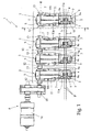
- reference number 1 designates as a whole a hot-rolling machine for wire rods and the like, which finds particularly advantageous use in the production of concrete-reinforcing bars.
- the machine 1 is basically made up of a series of rolling units 2 that are arranged in cascaded one after the other along the wire-rod feeding path p so that each rolling unit 2 can deform plastically the high-temperature metal, wire rod b that moves along the path p, causing a slight reduction of the nominal section thereof.
- the wire-rod feeding path p is substantially rectilinear and extends horizontally.
- Each rolling unit 2 is equipped with a rolling stand 3 that is arranged exactly on the wire-rod feeding path p, and is provided with two opposed and counter-rotating milling rollers 4 which have a substantially cylindrical shape and are arranged one beside the other, locally substantially parallel and substantially tangential to one another, so as to form/delimit a rolling groove or throttling 4a through which the wire rod b to be hot-rolled is forced to pass.
- the longitudinal axes L of the two milling rollers 4 are arranged substantially on a same laying plane T (parallel to the plane of the sheet in Figure 2 ), and are oriented so that the laying plane T is locally substantially perpendicular to the longitudinal axis of the wire rod, i.e. orthogonal to the feeding direction of the wire rod b along the path p, whilst the peripheral surfaces of the two milling rollers 4 are sized so as to form/delimit in between them selves a rolling groove or throttling 4a through which the wire rod b to be hot-rolled is forced to pass.
- the two hot mill milling rollers 4 are preferably, though not necessarily, arranged substantially horizontally position, one on top of the other.
- each rolling unit 2 is moreover equipped with a mechanical gear reduction unit 5, which is arranged beside the rolling stand 3 and is structured so as to be able to simultaneously drive into rotation the two milling rollers 4 about the respective longitudinal axes L substantially with identical peripheral velocities.
- each rolling unit 2 is structured so as to form, with the corresponding rolling stand 3, a single sectional elementary module 2 which is suitably structured for being aligned with other similar sectional elementary modules 2 along the wire-rod feeding path p, and for being mechanically coupled to the immediately adjacent sectional elementary modules 2 so as to compose/form a chain line of rolling units 2, which are reciprocally connected so as to transmit torque in cascade from one another.
- each rolling unit 2 is structured so to arrange its own mechanical gear reduction unit 5 adjacent to the mechanical gear reduction unit 5 of the other rolling unit or units 2 present along the wire-rod feeding path p, and the mechanical gear reduction unit 5 is structured so to be mechanically connectable directly to the mechanical gear reduction unit or reducers 5 of the immediately adjacent rolling units 2 so as to be able to form a cascade of mechanical gear reduction units 6 having a disassemblable structure, which extends parallel to the wire-rod feeding path p and is able to transmit the torque autonomously from one mechanical gear reduction unit 5 to another.
- each rolling unit 2 is preferably provided with a respective lower supporting platform 7, which is structured for being rigidly and stably anchored to the floor, and the rolling stand 3 and the mechanical gear reduction unit 5 of the rolling unit 2 are arranged on the lower supporting platform 7 one beside the other.
- the lower supporting platform 7 is substantially rectangular in shape and is anchored to the floor with its major side edges arranged locally substantially perpendicular to the feeding direction of the wire rod b along the path p.
- the wire-rods and the like hot-rolling machine 1 furthermore comprises a preferably, though not necessarily, electrically-or hydraulically- operated single shared drive unit 8 which is structured so to be mechanically connected to the mechanical gear reduction unit 5 of just one of the sectional elementary modules 2 that form the chain line of rolling units 2 so as to be able to simultaneously drive into rotation the milling rollers 4 of all the rolling units 2.
- a preferably, though not necessarily, electrically-or hydraulically- operated single shared drive unit 8 which is structured so to be mechanically connected to the mechanical gear reduction unit 5 of just one of the sectional elementary modules 2 that form the chain line of rolling units 2 so as to be able to simultaneously drive into rotation the milling rollers 4 of all the rolling units 2.
- the drive unit 8 is structured so to be mechanically connected to just one of the mechanical gear reduction units 5 that form the cascade of mechanical gear reduction units 6 so as to be able to simultaneously drive into rotation the milling rollers 4 of all the rolling units 2.
- the two milling rollers 4 of each rolling stand 3 are fixed in an axially rotatable manner on a rigid supporting frame 9, which is structured so as to prevent the two milling rollers 4 from receding with respect to one another when the wire rod b to be rolled passes through the rolling groove or throttling 4a delimited by the peripheral surfaces of the two milling rollers 4, thus deforming itself.
- the rigid supporting frame 9 is provided with two side walls 9a that are stably arranged parallel to and facing one another, and the two milling rollers 4 extend straddling the two side walls 9a of supporting frame 9, one beside the another, so that the longitudinal axes L of the two rolls are locally substantially orthogonal to the laying planes of the two side walls 9a, and are preferably arranged substantially horizontally, one on top of the other.
- each milling roller 4 has the two axial ends inserted in pass-through manner and trapped in an axially rotatable manner each within a corresponding side wall 9a of the supporting frame 9, and is shaped so that its central cross section can form/delimit, between the two side walls 9a, the rolling groove or throttling 4a through which the wire rod b to be rolled is forced to pass.
- the two milling rollers 4 are both provided with a roughly cylindrical-shaped central cross section which extends between the two lateral side walls 9a of the rigid supporting frame 9, and are arranged adjacent to one another so that the corresponding central sections are locally substantially tangent to one another and can form/delimit the rolling groove or throttling 4a through which the wire rod b to be rolled is forced to pass.
- the central sections of the two milling rollers 4 are preferably, though not necessarily, shaped so as to form/delimit a rolling groove or throttling 4a dimensioned for being engaged simultaneously by two wire rods b appropriately spaced apart from one another. Consequently, the wire-rod feeding path p can be engaged simultaneously by two high-temperature metal, wire rods b which move forward parallel to one another.
- the rolling stand 3 of each rolling unit 2 is moreover also provided with a preferably electrically- or hydraulically- operated, a device for adjusting the distance between the rollers which is structured so as to be able to approach or move away, on command, the two milling rollers 4 to one another so as to be able to adjust the distance between the longitudinal axes L of the two rolls 4 while maintaining the milling rollers 4 always horizontal and locally parallel to one another.
- a device for adjusting the distance between the rollers which is structured so as to be able to approach or move away, on command, the two milling rollers 4 to one another so as to be able to adjust the distance between the longitudinal axes L of the two rolls 4 while maintaining the milling rollers 4 always horizontal and locally parallel to one another.
- the rigid supporting frame 9 is preferably, though not necessarily, substantially U-shaped and it is rigidly fixed onto the lower supporting platform 7 so that its two side walls 9a overhangingly protrude upwards, in a substantially vertical direction; whilst the mechanical gear reduction unit 5 of the rolling unit 2 is fixed on the lower supporting platform 7, alongside the rolling stand 3, directly facing one of the two side walls 9a of the rigid supporting frame 9.
- the mechanical gear reduction unit 5 is preferably, though not necessarily, coupled in a rigid and stable, though disassemblable manner directly to the side walls 9a of the rigid supporting frame 9.
- the lower supporting platform 7, instead, is preferably, though not necessarily, structured so as to enable the rolling stand 3, or rather the rigid supporting frame 9 of the rolling stand 3, to translate horizontally towards and away from the mechanical gear reduction unit 5 in a horizontal direction f locally perpendicular to the two side walls 9a of the rigid supporting frame 9, i.e. parallel to the longitudinal axes L of the two milling rollers 4, so as to be able to uncouple, if need be, the rolling stand 3 from the corresponding mechanical gear reduction unit 5.
- the mechanical gear reduction unit 5 of each rolling unit 2 instead comprises: a rigid and substantially parallelepiped-shaped, outer boxlike casing 11 which is fixed on the lower supporting platform 7 with a first side wall 11a directly facing the side wall 9a of the rigid supporting frame 9 of the rolling stand 3; and two drive shafts 12 and 13, which extend inside the boxlike casing 11 parallel to a same reference axis R locally substantially parallel to the feeding direction of the wire rod b along the path p, and come out with their distal ends outside of the boxlike casing 11 on opposite sides of the rolling stand 3, once again in the feeding direction of the wire rod b.
- the two drive shafts 12 and 13 are parallel to a same reference axis R locally perpendicular to the laying plane T of the longitudinal axes L of the two milling rollers 4 of the rolling stand 3, and come out outside of the boxlike casing 11 on opposite sides of the rolling stand 3 in the feeding direction of the wire rod b along the path p.
- the distal ends of the two drive shafts 12 and 13 sticks out from the two side walls 11b of the boxlike casing 11 that are locally substantially orthogonal to the feeding direction of the wire rod b along path p so as to protrude from the sides of the side wall 9a of the rigid supporting frame 9, respectively in front of and behind the rolling stand 3 of the rolling units 2.
- the two drive shafts 12 and 13 are arranged coaxial to the reference axis R, one after the other, and overhangingly stick out from the two major side walls 11b of the boxlike casing 11.
- the distal end of the main drive shaft 12 is shaped so to be mechanically connectable in an angularly rigid manner to the drive shaft of drive unit 8 or, alternatively, to the distal end of the secondary drive shaft 13 of the immediately preceding rolling unit 2; whereas the distal end of the secondary drive shaft 13 is shaped so to be mechanically connectable in an angularly rigid manner to the distal end of the main drive shaft 12 of the immediately subsequent rolling unit 2.
- the distal end of the main drive shaft 12 is designed to be fitted on the drive shaft of the drive unit 8, or on the distal end of the secondary drive shaft 13 of the immediately preceding rolling unit 2 preferably, though not necessarily, via a first mechanical coupling joint of known type; whilst the distal end of the secondary drive shaft 13 is suited to be fitted on the distal end of the main drive shaft 12 of the immediately following rolling unit 2 preferably, though not necessarily, via a second mechanical coupling joint of known type.
- the mechanical gear reduction unit 5 furthermore comprises a gear-set (not shown) preferably, though not necessarily, of epicycloidal type, which is structured to connect the main drive shaft 12 with the two milling rollers 4 of the rolling stand 3, and with the secondary drive shaft 13, so as to transmit the torque to both of the components.
- a gear-set (not shown) preferably, though not necessarily, of epicycloidal type, which is structured to connect the main drive shaft 12 with the two milling rollers 4 of the rolling stand 3, and with the secondary drive shaft 13, so as to transmit the torque to both of the components.
- the gear-set of the mechanical gear reduction unit 5 is moreover dimensioned so that the rotating speed of the secondary drive shaft 13 is equal to that of the main drive shaft 12.
- the drive unit 8 is arranged alongside the first sectional elementary module 2 that forms the chain line of rolling units 2, so as to be aligned with the distal end of the main drive shaft 12 of the mechanical gear reduction unit 5 of the first sectional elementary module 2, and is preferably, though not necessarily, made up of a high-power electric motor 14 and a gear reducer 15 that connects the drive shaft of the electric motor 14 to the distal end of the main drive shaft 12 of the mechanical gear reduction unit 5 of the first sectional elementary module 2.
- a single electric motor 14 can simultaneously drive into rotation the two milling rollers 4 of all the rolling units 2 aligned along the wire-rod feeding path p, thus reducing the overall dimensions of the machine.
- each rolling unit 2 is constituted by a single sectional elementary module 2 greatly facilitates the transportation in loco and subsequent assemblage of the hot-rolling machine 1 for wire rods and the like.
- each rolling unit 2 is formed by a single sectional elementary module 2 considerably simplifies the design of the machine 1 for hot-rolling of wire rods and the like as a whole, and the production of the individual component parts.
- a second shared drive unit (not shown) can be arranged alongside the last sectional elementary module 2 that forms the chain line of rolling units 2 and be connected to the distal end of the secondary drive shaft 13 of the mechanical gear reduction unit 5 of the last sectional elementary module 2.
Landscapes
- Engineering & Computer Science (AREA)
- Mechanical Engineering (AREA)
- Metal Rolling (AREA)
- Reduction Rolling/Reduction Stand/Operation Of Reduction Machine (AREA)
- Laminated Bodies (AREA)
Claims (12)
- Machine de laminage à chaud (1) destinée à des tiges de fil métallique et similaires, qui comprend un certain nombre d'unités de laminage (2) qui sont disposées en cascade les unes après les autres le long du trajet d'alimentation des tiges de fil métallique (p), de sorte que chaque unité de laminage (2) puisse déformer plastiquement la tige de fil métallique à haute température (b) qui se déplace le long dudit trajet (p), chaque unité de laminage (2) étant munie- d'un support de laminage (3) qui se trouve sur le trajet d'alimentation en tiges de fil métallique (p) et est muni de deux rouleaux de fraisage opposés et en contre-rotation (4) qui sont placés l'un à côté de l'autre, de manière sensiblement parallèle et sensiblement tangentielle l'un par rapport à l'autre, de façon à former/définir une rainure de laminage ou un étranglement (4a) par lequel la tige de fil métallique (b) à laminer à chaud doit passer, et- d'une unité à réduction d'engrenage mécanique (5) qui est placée sous le support de laminage (3), et est structurée de façon à faire tourner simultanément deux rouleaux (4) autour d'axes longitudinaux respectifs (L),la machine de laminage à chaud (1) destinée à des tiges de fil métallique et similaires étant caractérisée :- en ce que chaque unité de laminage (2) comprend une plate-forme de support inférieure respective (7) qui est structurée de façon à être ancrée de manière rigide et stable sur le sol ;- en ce que le support de laminage (3) et l'unité à réduction d'engrenage mécanique (5) de chaque unité de laminage (2) sont placés sur la plate-forme de support inférieure correspondante (7) l'un à côté de l'autre, de façon à former un seul module élémentaire transversal (2) qui est structuré afin d'être aligné avec les autres modules élémentaires transversaux similaires (2), le long du trajet d'alimentation en tiges de fil métallique (p), l'unité à réduction d'engrenage mécanique (5) de l'unité de laminage (2) étant adjacente à l'unité à réduction d'engrenage mécanique (5) des autres unités de laminage (2) présentes le long du trajet d'alimentation en tiges de fil (p) ;- et en ce que l'unité à réduction d'engrenage mécanique (5) de chaque unité de laminage (2) est structurée de façon à pouvoir être reliée mécaniquement et directement aux unités à réduction d'engrenage mécanique (5) des unités de laminage immédiatement adjacentes (2), afin de former une cascade d'unités à réduction d'engrenage mécanique (6) qui s'étend parallèlement au trajet d'alimentation en tiges de fil métallique (p), qui possède une structure démontable, et qui est capable de transmettre un couple de manière autonome en cascade, d'une unité à réduction d'engrenage mécanique (5) à une autre.
- Machine de laminage à chaud selon la revendication 1, caractérisée en ce qu'elle comprend en outre au moins une unité d'entraînement partagée (8) qui est structurée de façon à être reliée mécaniquement à l'unité à réduction d'engrenage mécanique (5) d'un seul des modules élémentaires transversaux (2) qui forment la caténaire des unités de laminage (2).
- Machine de laminage à chaud selon l'une des revendications 1 ou 2, caractérisée en ce que l'unité à réduction d'engrenage mécanique (5) de chaque unité de laminage (2) comprend une enceinte extérieure (11), ainsi qu'un premier arbre d'entraînement (12) et un second arbre d'entraînement (13) qui s'étendent dans l'enceinte extérieure (11) parallèlement à un même axe de référence (R) sensiblement perpendiculaire au plan (T) des axes longitudinaux (L) des deux rouleaux de laminage (4) du support de laminage (3), et qui se font face en-dehors de l'enceinte extérieure (11) sur les côtés opposés du support de laminage (3), dans le sens d'alimentation de la tige de fil métallique (b).
- Machine de laminage à chaud selon la revendication 3, caractérisée en ce que l'unité à réduction d'engrenage mécanique (5) de chaque unité de laminage (2) comprend en outre, dans l'enceinte extérieure (11), un ensemble d'engrenages structuré de façon à relier ledit premier arbre d'entraînement (12) aux rouleaux (4) du support de laminage (3) et audit second arbre d'entraînement (13), afin de transmettre un couple aux deux composants.
- Machine de laminage à chaud selon l'une des revendications 3 ou 4, caractérisée en ce que ledit premier arbre d'entraînement (12) et ledit second arbre d'entraînement (13) sont placés de manière coaxiale par rapport audit axe de référence (R), l'un après l'autre.
- Machine de laminage à chaud selon l'une des revendications 3, 4 ou 5, caractérisée en ce que les extrémités distales dudit premier arbre d'entraînement (12) et dudit second arbre d'entraînement (13) sortent de deux parois latérales opposées (11b) de ladite enceinte extérieure (11).
- Machine de laminage à chaud selon l'une des revendications 3, 4, 5 ou 6, caractérisée en ce que l'extrémité distale dudit premier arbre d'entraînement (12) est structurée de façon à pouvoir être mécaniquement reliée à l'arbre d'entraînement de ladite unité d'entraînement partagée (8) ou, en variante, à l'extrémité distale du second arbre d'entraînement (13) de l'unité de laminage immédiatement précédente (2), et en ce que l'extrémité distale dudit second arbre d'entraînement (13) est formée de façon à pouvoir être mécaniquement reliée à l'extrémité distale du premier arbre d'entraînement (12) de l'unité de laminage à rouleaux immédiatement suivante (2).
- Machine de laminage à chaud selon l'une quelconque des revendications précédentes, caractérisée en ce que le support de laminage (3) de chaque unité de laminage (2) comprend également un dispositif de réglage de la distance entre les rouleaux (10), qui est structuré de façon à pouvoir rapprocher ou éloigner de manière sélectivement réciproque les deux rouleaux (4), afin de régler la distance entre les axes longitudinaux (L) des deux rouleaux (4).
- Machine de laminage à chaud selon l'une quelconque des revendications précédentes, caractérisée en ce que les deux rouleaux de fraisage (4) de chaque support de laminage (3) sont fixés de manière axialement rotative sur une armature de support rigide (9) qui est structurée afin d'empêcher les rouleaux (4) de s'éloigner l'un de l'autre lorsque la tige de fil (b) à laminer passe par la rainure de laminage ou l'étranglement (4a), ladite armature de support rigide (9) étant munie de deux parois latérales parallèles et qui se font face de manière réciproque (9a), et les deux rouleaux (4) étant disposés a cheval sur les deux parois latérales (9a) de l'armature de support (9), l'un à côté de l'autre.
- Machine de laminage à chaud selon la revendication 9, caractérisée en ce que l'armature de support rigide (9) est sensiblement en forme de U et est fixée de manière rigide sur la plate-forme de support inférieure (7) de sorte que les deux parois latérales (9a) sortent vers le haut, dans une direction sensiblement verticale, l'unité à réduction d'engrenage mécanique (5) de l'unité de laminage (2) étant fixée sur la plate-forme de support inférieure (7) à côté du support de laminage (3), directement face à l'une des deux parois latérales (9a) de l'armature de support rigide (9).
- Machine de laminage à chaud selon la revendication 10, caractérisée en ce que l'unité à réduction d'engrenage mécanique (5) est reliée à ladite paroi latérale (9a) de l'armature de support rigide (9) de manière rigide et stable, mais démontable.
- Machine de laminage à chaud selon la revendication 11, caractérisée en ce que la plate-forme de support inférieure (7) est structurée de façon à permettre au support de laminage (3) de se déplacer à l'horizontale depuis et vers l'unité à réduction d'engrenage mécanique correspondante (5), dans une direction (f) localement perpendiculaire aux deux parois latérales (9a) de l'armature de support rigide (9), de façon à découpler sélectivement le support de laminage (3) de l'unité à réduction d'engrenage mécanique correspondante (5).
Applications Claiming Priority (2)
| Application Number | Priority Date | Filing Date | Title |
|---|---|---|---|
| ITTV2011A000018A IT1403827B1 (it) | 2011-02-07 | 2011-02-07 | Macchina per la laminazione a caldo di vergelle ed affini. |
| PCT/IB2012/050553 WO2012107881A1 (fr) | 2011-02-07 | 2012-02-07 | Laminoir à chaud pour fil machine et d'autres produits semblables |
Publications (2)
| Publication Number | Publication Date |
|---|---|
| EP2673097A1 EP2673097A1 (fr) | 2013-12-18 |
| EP2673097B1 true EP2673097B1 (fr) | 2016-02-03 |
Family
ID=43976508
Family Applications (1)
| Application Number | Title | Priority Date | Filing Date |
|---|---|---|---|
| EP12710322.4A Active EP2673097B1 (fr) | 2011-02-07 | 2012-02-07 | Laminoir à chaud pour fil machine et d'autres produits semblables |
Country Status (6)
| Country | Link |
|---|---|
| US (1) | US20140041432A1 (fr) |
| EP (1) | EP2673097B1 (fr) |
| CN (1) | CN103501929B (fr) |
| IT (1) | IT1403827B1 (fr) |
| RU (1) | RU2013141175A (fr) |
| WO (1) | WO2012107881A1 (fr) |
Families Citing this family (1)
| Publication number | Priority date | Publication date | Assignee | Title |
|---|---|---|---|---|
| JP7251313B2 (ja) * | 2019-05-24 | 2023-04-04 | セイコーエプソン株式会社 | 画像読取装置 |
Citations (2)
| Publication number | Priority date | Publication date | Assignee | Title |
|---|---|---|---|---|
| US3587277A (en) * | 1968-09-30 | 1971-06-28 | Pomini Farrel Spa | Continuous rolling mill |
| EP0695589A1 (fr) * | 1994-08-01 | 1996-02-07 | Morgan Construction Company | Laminoir modulaire |
Family Cites Families (14)
| Publication number | Priority date | Publication date | Assignee | Title |
|---|---|---|---|---|
| US1962581A (en) * | 1929-05-25 | 1934-06-12 | Farrel Birmingham Co Inc | Drive mechanism for rolling mills and the like |
| BE473968A (fr) * | 1946-06-29 | |||
| FR1016392A (fr) * | 1950-03-27 | 1952-11-10 | Kocks Gmbh Friedrich | Laminoir à larges plats et laminoir à tubes |
| US3945234A (en) * | 1975-01-02 | 1976-03-23 | Rolf Steinbock | Tandem rolling mill arrangement |
| US4366694A (en) * | 1980-09-17 | 1983-01-04 | Morgan Construction Company | Compact rolling mill |
| JPS5788908A (en) * | 1980-11-19 | 1982-06-03 | Sumitomo Metal Ind Ltd | Method for controlling product dimension of wire rod finishing block mill |
| EP0163104B1 (fr) * | 1984-04-28 | 1989-11-29 | Sms Schloemann-Siemag Aktiengesellschaft | Cage de laminage |
| CN2049564U (zh) * | 1989-04-19 | 1989-12-20 | 冶金工业部北京冶金设备研究所 | 紧凑式连轧机组 |
| CN2267874Y (zh) * | 1996-12-19 | 1997-11-19 | 邱国荣 | 线材热轧机 |
| ITPN20010012A1 (it) * | 2001-02-15 | 2002-08-16 | Sms Demag Aktiengesellshaft | Blocco compatto di laminazione per due linee parallele. |
| ITMI20041526A1 (it) * | 2004-07-28 | 2004-10-28 | Vai Pomini Srl | "monoblocco finitore con rapporto di trasmissione ottimizzato per un impianto di laminazione di billette" |
| CN2761299Y (zh) * | 2005-01-13 | 2006-03-01 | 伊东新(德阳)线缆设备有限公司 | 金属线材连轧机 |
| US7523632B2 (en) * | 2007-02-15 | 2009-04-28 | Morgan Construction Company | Modular rolling mill |
| CN201431992Y (zh) * | 2009-06-26 | 2010-03-31 | 德阳博创电工设备有限公司 | 金属线材连轧机 |
-
2011
- 2011-02-07 IT ITTV2011A000018A patent/IT1403827B1/it active
-
2012
- 2012-02-07 CN CN201280007819.XA patent/CN103501929B/zh not_active Expired - Fee Related
- 2012-02-07 WO PCT/IB2012/050553 patent/WO2012107881A1/fr not_active Ceased
- 2012-02-07 US US13/984,184 patent/US20140041432A1/en not_active Abandoned
- 2012-02-07 EP EP12710322.4A patent/EP2673097B1/fr active Active
- 2012-02-07 RU RU2013141175/02A patent/RU2013141175A/ru not_active Application Discontinuation
Patent Citations (2)
| Publication number | Priority date | Publication date | Assignee | Title |
|---|---|---|---|---|
| US3587277A (en) * | 1968-09-30 | 1971-06-28 | Pomini Farrel Spa | Continuous rolling mill |
| EP0695589A1 (fr) * | 1994-08-01 | 1996-02-07 | Morgan Construction Company | Laminoir modulaire |
Also Published As
| Publication number | Publication date |
|---|---|
| CN103501929B (zh) | 2016-06-15 |
| CN103501929A (zh) | 2014-01-08 |
| EP2673097A1 (fr) | 2013-12-18 |
| IT1403827B1 (it) | 2013-10-31 |
| WO2012107881A1 (fr) | 2012-08-16 |
| RU2013141175A (ru) | 2015-03-20 |
| ITTV20110018A1 (it) | 2012-08-08 |
| US20140041432A1 (en) | 2014-02-13 |
Similar Documents
| Publication | Publication Date | Title |
|---|---|---|
| EP1844867B1 (fr) | Laminoir modulaire | |
| JP2012096290A (ja) | 圧延機、圧延機スタンド及び圧延機における圧延機スタンドの交換方法 | |
| KR20000023096A (ko) | 모듈식 압연기 | |
| KR102214017B1 (ko) | 압연 스테이션 및 압연기 플랜트 | |
| US20140041432A1 (en) | Hot-rolling machine for wire-rod and the like | |
| CN212442579U (zh) | 一种单机架独立传动模块化轧机及机组 | |
| CA2020721C (fr) | Train de laminage a rouleaux multiples montes sur support en porte-a-faux pour laminage a haute vitesse | |
| EP0790868B1 (fr) | Bloc de finition pour plusieurs barres filles | |
| JPH05337501A (ja) | 軽量形鋼/線材圧延ラインおよびこの圧延ラインを運転するための方法 | |
| RU2180873C2 (ru) | Многоклетьевой прокатный стан | |
| US6546776B2 (en) | High speed finishing block | |
| EP2747911B1 (fr) | Machine à laminer à chaud pour fil-machine et autres | |
| CA2802045A1 (fr) | Laminoir modulaire | |
| US20130047811A1 (en) | Multi-slit powered slitting machine | |
| CA2615023C (fr) | Dispositif d'entrainement pour dispositif de laminage |
Legal Events
| Date | Code | Title | Description |
|---|---|---|---|
| PUAI | Public reference made under article 153(3) epc to a published international application that has entered the european phase |
Free format text: ORIGINAL CODE: 0009012 |
|
| 17P | Request for examination filed |
Effective date: 20130809 |
|
| AK | Designated contracting states |
Kind code of ref document: A1 Designated state(s): AL AT BE BG CH CY CZ DE DK EE ES FI FR GB GR HR HU IE IS IT LI LT LU LV MC MK MT NL NO PL PT RO RS SE SI SK SM TR |
|
| DAX | Request for extension of the european patent (deleted) | ||
| 17Q | First examination report despatched |
Effective date: 20141024 |
|
| GRAP | Despatch of communication of intention to grant a patent |
Free format text: ORIGINAL CODE: EPIDOSNIGR1 |
|
| INTG | Intention to grant announced |
Effective date: 20150804 |
|
| GRAS | Grant fee paid |
Free format text: ORIGINAL CODE: EPIDOSNIGR3 |
|
| GRAA | (expected) grant |
Free format text: ORIGINAL CODE: 0009210 |
|
| AK | Designated contracting states |
Kind code of ref document: B1 Designated state(s): AL AT BE BG CH CY CZ DE DK EE ES FI FR GB GR HR HU IE IS IT LI LT LU LV MC MK MT NL NO PL PT RO RS SE SI SK SM TR |
|
| REG | Reference to a national code |
Ref country code: GB Ref legal event code: FG4D |
|
| REG | Reference to a national code |
Ref country code: AT Ref legal event code: REF Ref document number: 773404 Country of ref document: AT Kind code of ref document: T Effective date: 20160215 Ref country code: CH Ref legal event code: EP |
|
| REG | Reference to a national code |
Ref country code: IE Ref legal event code: FG4D |
|
| REG | Reference to a national code |
Ref country code: DE Ref legal event code: R096 Ref document number: 602012014370 Country of ref document: DE |
|
| REG | Reference to a national code |
Ref country code: LT Ref legal event code: MG4D Ref country code: NL Ref legal event code: MP Effective date: 20160203 |
|
| REG | Reference to a national code |
Ref country code: AT Ref legal event code: MK05 Ref document number: 773404 Country of ref document: AT Kind code of ref document: T Effective date: 20160203 |
|
| PG25 | Lapsed in a contracting state [announced via postgrant information from national office to epo] |
Ref country code: FI Free format text: LAPSE BECAUSE OF FAILURE TO SUBMIT A TRANSLATION OF THE DESCRIPTION OR TO PAY THE FEE WITHIN THE PRESCRIBED TIME-LIMIT Effective date: 20160203 Ref country code: GR Free format text: LAPSE BECAUSE OF FAILURE TO SUBMIT A TRANSLATION OF THE DESCRIPTION OR TO PAY THE FEE WITHIN THE PRESCRIBED TIME-LIMIT Effective date: 20160504 Ref country code: NO Free format text: LAPSE BECAUSE OF FAILURE TO SUBMIT A TRANSLATION OF THE DESCRIPTION OR TO PAY THE FEE WITHIN THE PRESCRIBED TIME-LIMIT Effective date: 20160503 Ref country code: ES Free format text: LAPSE BECAUSE OF FAILURE TO SUBMIT A TRANSLATION OF THE DESCRIPTION OR TO PAY THE FEE WITHIN THE PRESCRIBED TIME-LIMIT Effective date: 20160203 Ref country code: HR Free format text: LAPSE BECAUSE OF FAILURE TO SUBMIT A TRANSLATION OF THE DESCRIPTION OR TO PAY THE FEE WITHIN THE PRESCRIBED TIME-LIMIT Effective date: 20160203 |
|
| PG25 | Lapsed in a contracting state [announced via postgrant information from national office to epo] |
Ref country code: PL Free format text: LAPSE BECAUSE OF FAILURE TO SUBMIT A TRANSLATION OF THE DESCRIPTION OR TO PAY THE FEE WITHIN THE PRESCRIBED TIME-LIMIT Effective date: 20160203 Ref country code: RS Free format text: LAPSE BECAUSE OF FAILURE TO SUBMIT A TRANSLATION OF THE DESCRIPTION OR TO PAY THE FEE WITHIN THE PRESCRIBED TIME-LIMIT Effective date: 20160203 Ref country code: PT Free format text: LAPSE BECAUSE OF FAILURE TO SUBMIT A TRANSLATION OF THE DESCRIPTION OR TO PAY THE FEE WITHIN THE PRESCRIBED TIME-LIMIT Effective date: 20160603 Ref country code: BE Free format text: LAPSE BECAUSE OF NON-PAYMENT OF DUE FEES Effective date: 20160229 Ref country code: NL Free format text: LAPSE BECAUSE OF FAILURE TO SUBMIT A TRANSLATION OF THE DESCRIPTION OR TO PAY THE FEE WITHIN THE PRESCRIBED TIME-LIMIT Effective date: 20160203 Ref country code: LV Free format text: LAPSE BECAUSE OF FAILURE TO SUBMIT A TRANSLATION OF THE DESCRIPTION OR TO PAY THE FEE WITHIN THE PRESCRIBED TIME-LIMIT Effective date: 20160203 Ref country code: IS Free format text: LAPSE BECAUSE OF FAILURE TO SUBMIT A TRANSLATION OF THE DESCRIPTION OR TO PAY THE FEE WITHIN THE PRESCRIBED TIME-LIMIT Effective date: 20160603 Ref country code: SE Free format text: LAPSE BECAUSE OF FAILURE TO SUBMIT A TRANSLATION OF THE DESCRIPTION OR TO PAY THE FEE WITHIN THE PRESCRIBED TIME-LIMIT Effective date: 20160203 Ref country code: AT Free format text: LAPSE BECAUSE OF FAILURE TO SUBMIT A TRANSLATION OF THE DESCRIPTION OR TO PAY THE FEE WITHIN THE PRESCRIBED TIME-LIMIT Effective date: 20160203 Ref country code: LT Free format text: LAPSE BECAUSE OF FAILURE TO SUBMIT A TRANSLATION OF THE DESCRIPTION OR TO PAY THE FEE WITHIN THE PRESCRIBED TIME-LIMIT Effective date: 20160203 |
|
| REG | Reference to a national code |
Ref country code: DE Ref legal event code: R119 Ref document number: 602012014370 Country of ref document: DE |
|
| REG | Reference to a national code |
Ref country code: CH Ref legal event code: PL |
|
| PG25 | Lapsed in a contracting state [announced via postgrant information from national office to epo] |
Ref country code: LI Free format text: LAPSE BECAUSE OF NON-PAYMENT OF DUE FEES Effective date: 20160229 Ref country code: EE Free format text: LAPSE BECAUSE OF FAILURE TO SUBMIT A TRANSLATION OF THE DESCRIPTION OR TO PAY THE FEE WITHIN THE PRESCRIBED TIME-LIMIT Effective date: 20160203 Ref country code: DK Free format text: LAPSE BECAUSE OF FAILURE TO SUBMIT A TRANSLATION OF THE DESCRIPTION OR TO PAY THE FEE WITHIN THE PRESCRIBED TIME-LIMIT Effective date: 20160203 Ref country code: CH Free format text: LAPSE BECAUSE OF NON-PAYMENT OF DUE FEES Effective date: 20160229 |
|
| PG25 | Lapsed in a contracting state [announced via postgrant information from national office to epo] |
Ref country code: SK Free format text: LAPSE BECAUSE OF FAILURE TO SUBMIT A TRANSLATION OF THE DESCRIPTION OR TO PAY THE FEE WITHIN THE PRESCRIBED TIME-LIMIT Effective date: 20160203 Ref country code: RO Free format text: LAPSE BECAUSE OF FAILURE TO SUBMIT A TRANSLATION OF THE DESCRIPTION OR TO PAY THE FEE WITHIN THE PRESCRIBED TIME-LIMIT Effective date: 20160203 Ref country code: CZ Free format text: LAPSE BECAUSE OF FAILURE TO SUBMIT A TRANSLATION OF THE DESCRIPTION OR TO PAY THE FEE WITHIN THE PRESCRIBED TIME-LIMIT Effective date: 20160203 Ref country code: SM Free format text: LAPSE BECAUSE OF FAILURE TO SUBMIT A TRANSLATION OF THE DESCRIPTION OR TO PAY THE FEE WITHIN THE PRESCRIBED TIME-LIMIT Effective date: 20160203 |
|
| REG | Reference to a national code |
Ref country code: IE Ref legal event code: MM4A |
|
| PLBE | No opposition filed within time limit |
Free format text: ORIGINAL CODE: 0009261 |
|
| STAA | Information on the status of an ep patent application or granted ep patent |
Free format text: STATUS: NO OPPOSITION FILED WITHIN TIME LIMIT |
|
| PG25 | Lapsed in a contracting state [announced via postgrant information from national office to epo] |
Ref country code: BE Free format text: LAPSE BECAUSE OF FAILURE TO SUBMIT A TRANSLATION OF THE DESCRIPTION OR TO PAY THE FEE WITHIN THE PRESCRIBED TIME-LIMIT Effective date: 20160203 |
|
| 26N | No opposition filed |
Effective date: 20161104 |
|
| GBPC | Gb: european patent ceased through non-payment of renewal fee |
Effective date: 20160503 |
|
| REG | Reference to a national code |
Ref country code: FR Ref legal event code: ST Effective date: 20161226 |
|
| PG25 | Lapsed in a contracting state [announced via postgrant information from national office to epo] |
Ref country code: IE Free format text: LAPSE BECAUSE OF NON-PAYMENT OF DUE FEES Effective date: 20160207 Ref country code: DE Free format text: LAPSE BECAUSE OF NON-PAYMENT OF DUE FEES Effective date: 20160901 Ref country code: FR Free format text: LAPSE BECAUSE OF NON-PAYMENT OF DUE FEES Effective date: 20160404 |
|
| PG25 | Lapsed in a contracting state [announced via postgrant information from national office to epo] |
Ref country code: BG Free format text: LAPSE BECAUSE OF FAILURE TO SUBMIT A TRANSLATION OF THE DESCRIPTION OR TO PAY THE FEE WITHIN THE PRESCRIBED TIME-LIMIT Effective date: 20160503 Ref country code: SI Free format text: LAPSE BECAUSE OF FAILURE TO SUBMIT A TRANSLATION OF THE DESCRIPTION OR TO PAY THE FEE WITHIN THE PRESCRIBED TIME-LIMIT Effective date: 20160203 |
|
| PG25 | Lapsed in a contracting state [announced via postgrant information from national office to epo] |
Ref country code: GB Free format text: LAPSE BECAUSE OF NON-PAYMENT OF DUE FEES Effective date: 20160503 |
|
| PG25 | Lapsed in a contracting state [announced via postgrant information from national office to epo] |
Ref country code: MT Free format text: LAPSE BECAUSE OF FAILURE TO SUBMIT A TRANSLATION OF THE DESCRIPTION OR TO PAY THE FEE WITHIN THE PRESCRIBED TIME-LIMIT Effective date: 20160203 |
|
| PG25 | Lapsed in a contracting state [announced via postgrant information from national office to epo] |
Ref country code: CY Free format text: LAPSE BECAUSE OF FAILURE TO SUBMIT A TRANSLATION OF THE DESCRIPTION OR TO PAY THE FEE WITHIN THE PRESCRIBED TIME-LIMIT Effective date: 20160203 Ref country code: HU Free format text: LAPSE BECAUSE OF FAILURE TO SUBMIT A TRANSLATION OF THE DESCRIPTION OR TO PAY THE FEE WITHIN THE PRESCRIBED TIME-LIMIT; INVALID AB INITIO Effective date: 20120207 |
|
| PG25 | Lapsed in a contracting state [announced via postgrant information from national office to epo] |
Ref country code: MK Free format text: LAPSE BECAUSE OF FAILURE TO SUBMIT A TRANSLATION OF THE DESCRIPTION OR TO PAY THE FEE WITHIN THE PRESCRIBED TIME-LIMIT Effective date: 20160203 Ref country code: MC Free format text: LAPSE BECAUSE OF FAILURE TO SUBMIT A TRANSLATION OF THE DESCRIPTION OR TO PAY THE FEE WITHIN THE PRESCRIBED TIME-LIMIT Effective date: 20160203 Ref country code: LU Free format text: LAPSE BECAUSE OF NON-PAYMENT OF DUE FEES Effective date: 20160207 Ref country code: TR Free format text: LAPSE BECAUSE OF FAILURE TO SUBMIT A TRANSLATION OF THE DESCRIPTION OR TO PAY THE FEE WITHIN THE PRESCRIBED TIME-LIMIT Effective date: 20160203 Ref country code: MT Free format text: LAPSE BECAUSE OF FAILURE TO SUBMIT A TRANSLATION OF THE DESCRIPTION OR TO PAY THE FEE WITHIN THE PRESCRIBED TIME-LIMIT Effective date: 20160229 |
|
| PG25 | Lapsed in a contracting state [announced via postgrant information from national office to epo] |
Ref country code: AL Free format text: LAPSE BECAUSE OF FAILURE TO SUBMIT A TRANSLATION OF THE DESCRIPTION OR TO PAY THE FEE WITHIN THE PRESCRIBED TIME-LIMIT Effective date: 20160203 |
|
| PGFP | Annual fee paid to national office [announced via postgrant information from national office to epo] |
Ref country code: IT Payment date: 20260204 Year of fee payment: 15 |