EP2673103B1 - SCHWEIßGERÄT - Google Patents
SCHWEIßGERÄT Download PDFInfo
- Publication number
- EP2673103B1 EP2673103B1 EP12717145.2A EP12717145A EP2673103B1 EP 2673103 B1 EP2673103 B1 EP 2673103B1 EP 12717145 A EP12717145 A EP 12717145A EP 2673103 B1 EP2673103 B1 EP 2673103B1
- Authority
- EP
- European Patent Office
- Prior art keywords
- plugging
- power source
- cooling device
- welding
- connection
- Prior art date
- Legal status (The legal status is an assumption and is not a legal conclusion. Google has not performed a legal analysis and makes no representation as to the accuracy of the status listed.)
- Active
Links
Images


Classifications
-
- B—PERFORMING OPERATIONS; TRANSPORTING
- B23—MACHINE TOOLS; METAL-WORKING NOT OTHERWISE PROVIDED FOR
- B23K—SOLDERING OR UNSOLDERING; WELDING; CLADDING OR PLATING BY SOLDERING OR WELDING; CUTTING BY APPLYING HEAT LOCALLY, e.g. FLAME CUTTING; WORKING BY LASER BEAM
- B23K37/00—Auxiliary devices or processes, not specially adapted for a procedure covered by only one of the other main groups of this subclass
- B23K37/003—Cooling means for welding or cutting
-
- B—PERFORMING OPERATIONS; TRANSPORTING
- B23—MACHINE TOOLS; METAL-WORKING NOT OTHERWISE PROVIDED FOR
- B23K—SOLDERING OR UNSOLDERING; WELDING; CLADDING OR PLATING BY SOLDERING OR WELDING; CUTTING BY APPLYING HEAT LOCALLY, e.g. FLAME CUTTING; WORKING BY LASER BEAM
- B23K9/00—Arc welding or cutting
- B23K9/10—Other electric circuits therefor; Protective circuits; Remote controls
-
- B—PERFORMING OPERATIONS; TRANSPORTING
- B23—MACHINE TOOLS; METAL-WORKING NOT OTHERWISE PROVIDED FOR
- B23K—SOLDERING OR UNSOLDERING; WELDING; CLADDING OR PLATING BY SOLDERING OR WELDING; CUTTING BY APPLYING HEAT LOCALLY, e.g. FLAME CUTTING; WORKING BY LASER BEAM
- B23K9/00—Arc welding or cutting
- B23K9/32—Accessories
Definitions
- the invention relates to a welding apparatus having a power source arranged in a housing and a cooling device arranged in a housing for cooling a welding torch, wherein an electrical connection is provided between the power source and the cooling device, wherein the electrical connection between the power source and the cooling device by a Plug connection with at least two plug parts is formed with corresponding contacts, wherein at least one plug part of the plug connection with the power source and at least one plug part of the plug connection is connected to the cooling device, so that the plug parts of the plug connection are automatically connected in the arrangement of the power source to the cooling device.
- Welding machines of the subject type are suitable for various welding methods, such as e.g. MIG / MAG welding, TIG / TIG welding, electrode welding, double wire tandem welding, plasma or soldering, etc.
- a cooling device is provided for cooling the welding torch, which in the case of liquid cooling has a container for the cooling liquid, which is led to the components to be cooled.
- a corresponding electrical connection between the power source of the welding device and the cooling device is required.
- this electrical connection is realized by appropriate cables, which are connected by appropriately trained personnel with the corresponding components in the power source and the cooling device.
- the US 5,189,277 A describes a welding machine with a power section, which can be extended by stacking. Connections at the bottom and top of the modules ensure an electrical connection between the modules.
- the US 4,839,499 A describes a system for powering various cutting torches with electrical energy, deactivating contacts when the device is in a condition where these contacts are not secured.
- the object of the present invention is therefore to provide a welding device which avoids the above-mentioned disadvantage and simplifies connection of the power source to the cooling device or disassembly of the power source from the cooling device and also allows a passage through not specially trained personnel without risk.
- the object of the invention is achieved by an above-mentioned welder bei'dem at least energized contacts of the at least one plug connected to the power source plug part are disconnected on separation of the at least two connector parts of the connector, in which at least the current-carrying contacts of the at least one plug connected to the power source plug part each two superimposed and connected in series switches are connected, and a switch of the series-connected switch by at least one arranged on at least one arranged on the upper side of the housing of the cooling device connector part actuator when connecting the connector parts of the connector is actuated, which operation of the one Switch is forwarded to the switch arranged above it.
- the connector thus the corresponding components of the power source and cooling device are automatically connected to each other without the housing of the power source and the cooling device open and connected the lines Need to become.
- the preparation or separation of the compound can be accelerated and also made by not specially trained personnel.
- Provided a corresponding design of the connector parts of the connector and no shutdown of the power source or separation of the power source from the power supply before the production or separation of the electrical connection is absolutely necessary without it comes to the users of the welding machine to security losses.
- deactivating at least live contacts of the plug part of the connector ensures that even when not disconnected or disconnected from the power supply power source and disconnect the power source of the cooling device no risk to the user can take place.
- a short circuit can occur.
- the actuating element can be formed for example by a pin or the like., Which can be inserted into a corresponding receiving opening on the plug part, which is connected to the power source, so that the corresponding switch can be closed or opened.
- Safety can be increased by connecting each live contact to two or more switches connected in series. As a result, it can be ensured with high probability that the current-carrying contact is de-energized when the power source is lifted from the cooling device, even if, for example, a switch remains closed due to a mechanical problem or fused contacts.
- the at least one plug-in part connected to the power source is arranged on the underside of the housing of the power source and the at least one connected to the cooling device plug part of the connector at the top of the housing of the cooling device, so that when the power source on the cooling device, the plug parts of the connector automatically connected.
- the plug-in part connected to the power source can also be arranged on the underside of an intermediate module which can be arranged between the current source and the cooling device and the at least one plug-in part of the plug-in connection connected to the cooling device can be arranged on the upper side of the housing of the cooling device, so that when the intermediate module is arranged on the Cooling device, the connector parts of the connector are automatically connected.
- This embodiment variant, in which an intermediate module is provided between the power source and the cooling device is particularly suitable for the retrofitting of existing power sources by connecting the power source to the intermediate module and an electrical connection between the power source and the plug part arranged on the underside of the intermediate module the connector is made.
- a connector can be arranged in the same way as it is between the power source and the cooling device without the arrangement of an intermediate module of the case.
- At least one device for centering the connector parts may be provided.
- the appropriately designed centering thus ensures proper connection of the connector parts of the connector.
- the centering device can by a arranged around the at least one connector part frame element with inclined inner surfaces and arranged around the at least one other plug part be further frame member formed with the oblique inner surfaces corresponding formed oblique outer surfaces. Apart from the centering such frame members also form a protection for the respective connector part. If the frame element projects beyond the plug part, is thus at a settling For example, the power source ensures that the plug part does not rest on the ground and is dirty or damaged.
- the shape and design of the centering or frame elements is no limit.
- the frame elements are arranged separately from the plug parts surrounding them, a so-called floating mounting of the plug in the respective housing of the component of the welding device can be realized.
- the plug part relative to the frame member is slidably mounted within certain limits, which tolerances can be compensated.
- the frame member may also be made in one piece with the respective plug part surrounding it, whereby a displacement of the plug part with respect to the frame element is not possible, provided that the plug part is firmly in the respective housing complained.
- a floating mounting of the plug part in the respective housing of the component of the welding device can be achieved in that the plug part is connected together with the frame element displaceable with the housing.
- a corresponding cover can be arranged. It is advantageous if the lid can be locked in the open position, so that the lid when placing the power source on the cooling device is not a hindrance.
- the plug parts of the power source or the intermediate module and the cooling device are arranged off-center on the underside of the housing of the power source or the bottom of the intermediate module and the top of the housing of the cooling device. Due to the off-center arrangement of the connector parts is at flush arrangement of the components of the welding machine above each other only allows the desired connection of the connector parts.
- the underside of the housing of the power source and or or on the underside of the intermediate module connecting elements and at the top of the housing of the cooling device and possibly at the top of the intermediate module corresponding receiving elements for receiving the connecting elements be provided on the underside of the power source, preferably at the corners, which fit into corresponding holes on the upper side of the housing of the cooling device.
- locking elements for locking the connection of the power source with the cooling device and possibly the intermediate module may be provided.
- Such locking elements can be formed, for example, by connecting bolts, screws or the like.
- the at least one connected to the power source plug part of the connector is preferably formed by a socket with recessed contacts and the at least one plug connected to the cooling device plug part by a connector suitable for the socket. Due to the design of the power source connected to the plug part as a socket contact with live contacts is effectively prevented.
- Fig. 1 shows a welding apparatus 1 for a variety of processes or processes, such as MIG / MAG welding or TIG / TIG welding or electrode welding process, double wire / tandem welding, plasma or soldering, etc .
- the welding machine 1 comprises a power source 2 with a power unit 3, a control device 4 and other components and lines, not shown, such as a switching element, control valves, etc ..
- the power source 2 and its components are arranged in a corresponding housing 11.
- the control device 4 is connected, for example, to a control valve which is arranged in a supply line for an inert gas, such as CO 2 , helium or argon and the like, between a gas reservoir 6 and a welding torch 7.
- an inert gas such as CO 2 , helium or argon and the like
- a wire feeder 8 which is customary for MIG / MAG welding, can be actuated via the control device 4, wherein a filler material or a welding wire 9 from a supply drum 10 or a wire reel into the area of the welding torch 7 via a supply line is supplied.
- the wire feeder 8 can also be placed directly on the welding device 2 by the housing 11 of the power source 2 is formed at the top for receiving the wire feeder 8. In this case, the carriage 12 can also be omitted.
- the wire feed unit 8 can also supply the welding wire 9 outside the welding torch 7 to the processing station, wherein a non-consumable electrode is preferably arranged in the welding torch 7, as is usual in TIG / TIG welding.
- the current for establishing an arc 13 between the electrode or the welding wire 9 and a workpiece 14 is supplied via a welding line (not shown) from the power part 3 of the power source 2, the welding torch 7, in particular the electrode or the welding wire 9.
- the workpiece 14 to be welded is connected via a further welding line for the further potential, in particular the ground cable, to the power source 2, so that a circuit can be constructed via the arc 13.
- a cooling device 15 For cooling the welding torch 7, this can be done via a cooling device 15 with the interposition of any components, such as For example, a flow switch, with a liquid container, in particular a water tank 16 with a level indicator 17, are connected.
- the cooling device 15 and its components are arranged in a corresponding housing 23.
- the individual components of the welding system, that is to say the current source 2, the wire feed device 8 and the cooling device 15, are designed in such a way that they can be safely stacked on top of each other or placed one upon the other.
- the welding device 1, in particular the current source 2, further has an input and / or output device 18, via which the most varied welding parameters, operating modes or welding programs of the welding device 1 can be set or called up and displayed.
- the welding parameters, operating modes or welding programs set via the input and / or output device 18 are forwarded to the control device 4 and from this the individual components of the welding device 1 are subsequently controlled or corresponding setpoint values for regulation or control are specified.
- adjustment operations can also be made via the welding torch 7.
- the welding torch 7 is preferably connected via a data bus, in particular a serial data bus, to the welding device 1, in particular the current source 2 or the wire feed device 8.
- the welding torch 7 usually has a start switch (not shown), so that the arc 13 can be ignited by actuating the start switch.
- the welding torch 7 is equipped with a heat shield 20.
- the welding torch 7 is connected via a hose package 21 to the welding apparatus 1, the hose assembly 21 being fastened to the welding torch 7 via a bend protection 22.
- the hose package 21 are the individual lines, such as the supply line or lines for the welding wire 9, for the gas 5, for the cooling circuit, for data transmission, etc., from
- the welding torch 7 can be designed as an air-cooled welding torch 7, so that, for example, the cooling device 15 can be dispensed with. It can therefore be said that the welding device 1 is formed at least by the current source 2, the wire feeder 8 and the cooling device 15, which may also be arranged in a common housing 11.
- Fig. 2 shows a schematic, partially sectioned or opened side view of a power source 2, which is arranged on an associated cooling device 15.
- the plug part 26 of the plug connection 25 connected to the power source 2 is arranged on the underside of the housing 11 of the power source 2 and the associated plug part 27 connected to the cooling device 15 is placed on the top side of the housing 23 of the cooling device 15.
- the connector parts 26, 27 of the connector 25 are contacted automatically and thus the required electrical connection between the power source 2 and the cooling device 15 produced.
- the contacts of the connector parts 26, 27 may be formed in various ways and electrical energy for operating a pump in the cooling device 15 and also control signals from the power source 2 to the cooling device 15 or sensor signals from the cooling device 15 to the power source 2 transmitted.
- the contacts may also be formed by optical transmitting and receiving devices for the transmission and reception of optical signals.
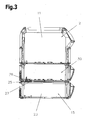
- Fig. 3 shows one opposite Fig. 2 extended embodiment, wherein an intermediate module 30 between the power source 2 and the cooling device 15 is arranged.
- the connector part 26 connected to the power source 2 is the connector 25 arranged on the underside of the intermediate module 30.
- the plug part 26 can be connected to the corresponding components of the current source 2 via conventional lines running internally in the intermediate module 30 and the current source 2.
- the plug part 26 associated plug part 27 which is connected to the cooling device 15, in turn, at the top of the housing 23 of the cooling device 15 is arranged so that when placing the intermediate module 30 on the cooling device 15 automatically contacting the plug part 26, 27 of the connector 25th takes place.
- FIG. 4 and FIG. 5 show a perspective view and a sectional view of an embodiment of a connector part 26 which is connected to the power source 2.
- the plug part 26 contains the corresponding contacts 28, which are connected via conventional lines to the corresponding components of the power source 2.
- at least current-carrying contacts 31 of the plug part 26 can be connected to corresponding switches 32, whereby the current-carrying contacts 31 are automatically deactivated when the plug parts 26, 27 of the plug connection 25 are disconnected.
- the switches 32 are actuated via corresponding actuating elements 34 on the opposite plug part 27, which protrude into a receiving opening 33 provided for this purpose and close the contacts of the switches 32 in the case of connected plug parts 26, 27. This ensures that, when the plug parts 26, 27 are disconnected, the current-carrying contacts 31 of the plug-in part 26 connected to the current source 2 are automatically deactivated.
- the plug parts 26, 27 may be provided a corresponding centering device.
- this centering device is formed by a arranged around the plug member 26 frame member 35 which has inclined inner surfaces 36.
- the frame member 35 fits the corresponding counterpart of the connected to the cooling device 15 connector part 27, as shown in the FIGS. 6 and 7 will be explained.
- the frame element 35 also has a protective effect, since it is the contacts 28 of the plug part 26 preferably surmounted. If the power source 2 is lifted from the cooling device 15 and parked, for example, on the ground, thus ensuring the frame member 35 is a protection of the contacts 28, 31 of the connector part 26 from damage and contamination.
- Fig. 6 and Fig. 7 show a perspective view and a sectional view of a connector 25 with a to be connected to the power source 2 connector part 26 according to the 4 and 5 and a mating male part 27, which is connected to the cooling device 15.
- the plug part 27 also comprises the mentioned actuating element 34, which may be in the form of a pin and projects into the recess 33 of the switch 32 on the plug part 26 and actuates the switches 32 accordingly.
- actuating element 34 which may be in the form of a pin and projects into the recess 33 of the switch 32 on the plug part 26 and actuates the switches 32 accordingly.
- a frame member 35 to the inclined inner surfaces 36 of the male part 26 complementary designed frame member 37 is disposed on the plug part 27, which is equipped with corresponding obliquely extending outer surfaces 38.
- each two switches 32 are arranged one above the other on the plug part 26, wherein the one switch 32 is actuated by the arranged on the opposite plug part 27 actuator 34 and via an internal mechanism, the confirmation is forwarded to the switch 32 disposed above.
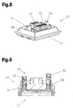
- the 8 and 9 show a further embodiment of a connector 25th Fig. 8 shows a perspective view of the connector to be connected to the cooling device 15 27, wherein with respect to the in the Fig. 4 to 7 illustrated embodiment, two actuating element 34 are arranged.
- 27 corresponding to the plug part 26 arranged switch 32 is actuated by the actuating elements 34 on the plug part.
- the plug parts 26, 27 can also be connected in a floating manner to the housing 11 of the power source 2 or housing 23 of the cooling device 15, with certain lateral displacements being permitted. As a result, tolerances can be compensated and damage to the connector parts 26, 27 of the connector 25 can be prevented.
- the show 10 and 11 a further embodiment of the connector parts 26 and 27 in a perspective view.
- a lid 39 is provided, through which the plug part 26 can be covered and protected when the power source 2 is separated from the cooling device 15. It is advantageous if the lid 39 can be locked in the open position, so that the lid 39 is not hindering when plugging the power source 2 and the cooling device 15.
- the plug part 26 according to Fig. 10 also differs from the embodiments described above in that two switches 32 are arranged on one side of the plug part 26.
- the two switches 32 are connected in series with the current-carrying contacts 31 of the plug part 26, a separation of the current-carrying contacts 31 of the plug part 26 can be achieved by the power supply, for example, if a switch 32 blocked or its contacts are fused.
- the safety can be further increased by the series connection of at least two switches 32.
- Fig. 11 shows the plug part 26 according to Fig. 10 associated plug part 27 which is connected to the cooling device 15.
- the switch 32 on the plug part 26 according to Fig. 10 are two actuators 34 for actuating the switch 32 on the connector part 27 is arranged.
- the present invention enables the simple docking of the cooling device 15 to the power source 2 of a welding machine 1, without the need for elaborate and dangerous connection work to be carried out by appropriate specialist personnel.
- Appropriate Measures and constructions of the connector parts 26, 27 provided a contact of live parts is prevented at the separate from the cooling device 15 power source 2. It can also be prevented by appropriate mechanical and / or electrical precautions that connected to the power source 2 plug part 26 of the connector 25 comes into contact with conductive surfaces and thereby short circuits and damage to the power source 2 occur.
Landscapes
- Engineering & Computer Science (AREA)
- Physics & Mathematics (AREA)
- Mechanical Engineering (AREA)
- Plasma & Fusion (AREA)
- Optics & Photonics (AREA)
- Connector Housings Or Holding Contact Members (AREA)
- Arc Welding Control (AREA)
Description
- Die Erfindung betrifft ein Schweißgerät, mit einer in einem Gehäuse angeordneten Stromquelle und einer in einem Gehäuse angeordneten Kühleinrichtung zum Kühlen eines Schweißbrenners, wobei zwischen der Stromquelle und der Kühleinrichtung eine elektrische Verbindung vorgesehen ist, wobei die elektrische Verbindung zwischen der Stromquelle und der Kühleinrichtung durch eine Steckverbindung mit zumindest zwei Steckerteilen mit entsprechenden Kontakten gebildet ist, wobei zumindest ein Steckerteil der Steckverbindung mit der Stromquelle und zumindest ein Steckerteil der Steckverbindung mit der Kühleinrichtung verbunden ist, sodass bei Anordnung der Stromquelle an der Kühleinrichtung die Steckerteile der Steckverbindung automatisch verbunden sind.
- Schweißgeräte der gegenständlichen Art sind für verschiedene Schweißverfahren wie z.B. MIG/MAG-Schweißverfahren, WIG/TIG-Schweißverfahren, Elektroden-Schweißverfahren, Doppeldraht-Tandem-Schweißverfahren, Plasma- oder Lötverfahren usw. ausgelegt. Üblicherweise ist eine Kühleinrichtung zum Kühlen des Schweißbrenners vorgesehen, die im Falle einer Flüssigkeitskühlung einen Behälter für die Kühlflüssigkeit aufweist, welche zu den zu kühlenden Komponenten geführt wird. Zur Versorgung der Komponenten der Kühleinrichtung mit elektrischer Energie und zur Steuerung der Kühleinrichtung ist eine entsprechende elektrische Verbindung zwischen der Stromquelle des Schweißgeräts und der Kühleinrichtung erforderlich. Üblicherweise wird diese elektrische Verbindung durch entsprechende Kabel realisiert, welche von entsprechend geschultem Fachpersonal mit den entsprechenden Komponenten in der Stromquelle und der Kühleinrichtung verbunden werden. Zu diesem Zweck ist es erforderlich die Gehäuse der Stromquelle und der Kühleinrichtung zu öffnen und die notwendigen Verbindungen herzustellen. Dies stellt einen erhöhten Arbeitsaufwand und auch ein Sicherheitsrisiko für das Personal dar. Vor einer entsprechenden Manipulation an der Stromquelle des Schweißgeräts ist daher üblicherweise eine Abschaltung der Spannungsversorgung aus Sicherheitsgründen vorgeschrieben.
- Im Falle einer Umrüstung der Kühleinrichtung, beispielsweise von Wasserkühlung auf Gaskühlung oder im Falle der Verwendung des Schweißgeräts ohne Kühlung, ist ein Wechsel oder eine Demontage der Kühleinrichtung und somit der entsprechenden elektrischen Verbindung notwendig. Bei Schweißgeräten des Standes der Technik stellt dies einen relativ zeitaufwändigen Prozess dar, der üblicherweise nur von entsprechend geschultem Person durchgeführt werden kann.
- Die
US 5,189,277 A beschreibt ein Schweißgerät mit einem Leistungsteil, welches durch Übereinanderstapeln erweitert werden kann. Über Steckverbindungen an der Unterseite und Oberseite der Module wird eine elektrische Verbindung zwischen den Modulen gewährleistet. - Die
US 4,839,499 A beschreibt ein System zur Versorgung verschiedener Schneidbrenner mit elektrischer Energie, wobei Kontakte deaktiviert werden, wenn sich das Gerät in einem Zustand befindet, in dem diese Kontakte nicht gesichert sind. - Die Aufgabe der vorliegenden Erfindung besteht daher in der Schaffung eines Schweißgeräts, welches den oben genannten Nachteil vermeidet und eine Verbindung der Stromquelle mit der Kühleinrichtung oder Demontage der Stromquelle von der Kühleinrichtung vereinfacht und auch eine Durchführung durch nicht speziell geschultes Personal ohne Risiko zulässt.
- Gelöst wird die erfindungsgemäße Aufgabe durch ein oben genanntes Schweißgerät bei'dem zumindest stromführende Kontakte des zumindest einen mit der Stromquelle verbundenen Steckerteils bei Trennung der zumindest zwei Steckerteile der Steckverbindung deaktiviert sind, in dem zumindest die stromführenden Kontakte des zumindest einen mit der Stromquelle verbundenen Steckerteils mit jeweils zwei übereinander angeordneten und in Serie geschalteten Schaltern verbunden sind, und ein Schalter der in Serie geschalteten Schalter durch zumindest ein am zumindest einen an der Oberseite des Gehäuses der Kühleinrichtung angeordneten Steckerteil angeordnetes Betätigungselement bei Verbindung der Steckerteile der Steckverbindung betätigbar ist, welche Betätigung des einen Schalters an den darüber angeordneten Schalter weiterleitbar ist. Durch die Steckverbindung werden somit die entsprechenden Komponenten der Stromquelle und Kühleinrichtung automatisch miteinander verbunden, ohne dass die Gehäuse der Stromquelle und der Kühleinrichtung geöffnet und die Leitungen angeschlossen werden müssen. Dadurch kann die Herstellung oder Trennung der Verbindung beschleunigt und auch durch nicht speziell geschultes Fachpersonal vorgenommen werden. Unter der Voraussetzung einer entsprechenden Gestaltung der Steckerteile der Steckverbindung ist auch keine Abschaltung der Stromquelle oder Trennung der Stromquelle von der Spannungsversorgung vor der Herstellung oder Trennung der elektrischen Verbindung zwingend erforderlich ohne dass es für die Benutzer des Schweißgeräts zu Sicherheitseinbußen kommt. Durch die Deaktivierung zumindest stromführender Kontakte des Steckerteils der Steckverbindung wird sichergestellt, dass auch bei nicht abgeschalteter oder von der Spannungsversorgung getrennter Stromquelle und Trennung der Stromquelle von der Kühleinrichtung keine Gefährdung für den Benutzer stattfinden kann. Dadurch wird auch verhindert, dass beispielsweise beim Abstellen der Stromquelle mit an der Unterseite angeordnetem Steckerteil auf einem elektrisch leitenden Grund, beispielsweise einem feuchten Boden, ein Kurzschluss auftreten kann. Durch eine derartige Konstruktion wird sichergestellt, dass bei Trennung der Stromquelle oder des Zwischenmoduls von der Kühleinrichtung allenfalls stromführende Kontakte des mit der Stromquelle verbundenen Steckerteils sicher deaktiviert werden. Das Betätigungselement kann beispielsweise durch einen Zapfen oder dgl. gebildet sein, der in eine entsprechende Aufnahmeöffnung am Steckerteil, der mit der Stromquelle verbunden ist, einführbar ist, sodass der entsprechende Schalter geschlossen bzw. geöffnet werden kann. Die Sicherheit kann dadurch erhöht werden, dass jeder stromführende Kontakt mit zwei oder mehr in Serie geschalteten Schaltern verbunden wird. Dadurch kann mit hoher Wahrscheinlichkeit sichergestellt werden, dass der stromführende Kontakt beim Abheben der Stromquelle von der Kühleinrichtung stromlos ist, auch wenn beispielsweise ein Schalter aufgrund eines mechanischen Problems oder zusammengeschmolzener Kontakte geschlossen bleibt.
- Vorteilhafterweise ist der zumindest eine mit der Stromquelle verbundene Steckerteil an der Unterseite des Gehäuses der Stromquelle und der zumindest eine mit der Kühleinrichtung verbundene Steckerteil der Steckverbindung an der Oberseite des Gehäuses der Kühleinrichtung angeordnet, sodass bei Anordnung der Stromquelle auf der Kühleinrichtung die Steckerteile der Steckverbindung automatisch verbunden sind. Dies stellt eine bevorzugte Ausführungsform dar, durch welche es bei der üblichen Anordnung der Stromquelle auf der Kühleinrichtung bzw. dem Kühlmodul automatisch zur Herstellung der notwendigen elektrischen Verbindung kommt.
- Alternativ dazu kann der mit der Stromquelle verbundene Steckerteil auch an der Unterseite eines zwischen der Stromquelle und der Kühleinrichtung anordenbaren Zwischenmoduls und der zumindest eine mit der Kühleinrichtung verbundene Steckerteil der Steckverbindung an der Oberseite des Gehäuses der Kühleinrichtung angeordnet sein, sodass bei Anordnung des Zwischenmoduls auf der Kühleinrichtung die Steckerteile der Steckverbindung automatisch verbunden sind. Diese Ausführungsvariante, bei welcher ein Zwischenmodul zwischen der Stromquelle und der Kühleinrichtung vorgesehen ist, eignet sich insbesondere für die nachträgliche Umrüstung vorhandener Stromquellen, indem die Stromquelle mit dem Zwischenmodul verbunden wird und eine elektrische Verbindung zwischen der Stromquelle und dem an der Unterseite des Zwischenmoduls angeordnet Steckerteil der Steckverbindung hergestellt wird. Selbstverständlich kann zwischen der Stromquelle und dem Zwischenmodul ebenfalls eine Steckverbindung angeordnet werden in der selben Art, wie es zwischen der Stromquelle und der Kühleinrichtung ohne Anordnung eines Zwischenmoduls der Falls ist.
- Um eine sichere Verbindung der Steckerteile der Steckverbindung ohne Beschädigung der Kontakte zu gewährleisten, kann zumindest eine Vorrichtung zur Zentrierung der Steckerteile vorgesehen sein. Die entsprechend gestaltete Zentriervorrichtung gewährleistet somit ein ordnungsgemäßes Verbinden der Steckerteile der Steckverbindung.
- Die Zentriervorrichtung kann durch ein um den zumindest einen Steckerteil angeordnetes Rahmenelement mit schrägen Innenflächen und ein um den zumindest einen weiteren Steckerteil angeordnetes weiteres Rahmenelement mit zu den schrägen Innenflächen korrespondierend ausgebildeten schrägen Außenflächen gebildet sein. Abgesehen von der Zentrierwirkung bilden derartige Rahmenelemente auch einen Schutz für den jeweiligen Steckerteil. Wenn das Rahmenelement den Steckerteil überragt, wird somit bei einem Absetzen beispielsweise der Stromquelle sichergestellt, dass der Steckerteil nicht auf dem Untergrund aufliegt und verschmutzt oder beschädigt wird. Der Form und Gestaltung der Zentriervorrichtung bzw. Rahmenelemente ist keine Grenze gesetzt.
- Wenn die Rahmenelemente von den durch sie umgebenden Steckerteilen getrennt angeordnet sind, kann eine sogenannte schwimmende Lagerung des Steckers im jeweiligen Gehäuse der Komponente des Schweißgeräts realisiert werden. Dabei ist der Steckerteil gegenüber dem Rahmenelement in bestimmten Grenzen verschieblich gelagert, wodurch Toleranzen ausgeglichen werden können.
- Alternativ dazu kann das Rahmenelement auch mit dem jeweiligen durch ihn umgebenden Steckerteil einstückig hergestellt sein, wodurch eine Verschiebung des Steckerteils im Bezug auf dar Rahmenelement nicht möglich ist, sofern der Steckerteil fest im jeweiligen Gehäuse moniert ist. Allerdings kann auch in diesem Fall eine schwimmende Lagerung des Steckerteils im jeweiligen Gehäuse der Komponente des Schweißgeräts dadurch erzielt werden, dass der Steckerteil zusammen mit dem Rahmenelement verschieblich mit dem Gehäuse verbunden wird.
- Um eine Verschmutzung, zumindest des mit der Stromquelle verbundenen zumindest einen Steckerteils zu verhindern und auch Berührung der elektrischen Kontakte zu vermeiden, kann ein entsprechender Deckel angeordnet sein. Dabei ist es von Vorteil, wenn der Deckel in der geöffneten Stellung arretierbar ist, so dass der Deckel beim Anordnen der Stromquelle auf der Kühleinrichtung nicht hinderlich ist.
- Von Vorteil ist es, wenn ein solcher Deckel vorzugsweise automatisch bei Verbindung der Steckerteile der Steckverbindung vom jeweiligen Steckerteil wegbewegbar ist.
- Um Fehlkontaktierungen der Steckerteile der Stromquelle bzw. des Zwischenmoduls und der Kühleinrichtung zu vermeiden, ist es von Vorteil, wenn die Steckerteile außermittig an der Unterseite des Gehäuses der Stromquelle oder der Unterseite des Zwischenmodul und der Oberseite des Gehäuses der Kühleinrichtung angeordnet sind. Durch die außermittige Anordnung der Steckerteile wird bei bündiger Anordnung der Komponenten des Schweißgeräts übereinander nur die gewünschte Verbindung der Steckerteile ermöglicht.
- Um eine optimale Verbindung der Komponenten des Schweißgeräts zu ermöglichen, können an der Unterseite des Gehäuses der Stromquelle und bzw. oder an der Unterseite des Zwischenmoduls Verbindungselemente und an der Oberseite des Gehäuses der Kühleinrichtung und allenfalls an der Oberseite des Zwischenmodul entsprechende Aufnahmeelemente zur Aufnahme der Verbindungselemente vorgesehen sein. Beispielsweise können an der Unterseite der Stromquelle vorzugsweise an den Ecken Füße angeordnet sein, welche in entsprechende Löcher an der Oberseite des Gehäuses der Kühleinrichtung passen. Dadurch wird auch die Verbindung der Steckerteile unterstützt und ein nachträgliches seitliches Verschieben der Stromquelle gegenüber der Kühleinrichtung verhindert.
- Weiters können Verriegelungselemente zur Verriegelung der Verbindung der Stromquelle mit der Kühleinrichtung und allenfalls dem Zwischenmodul vorgesehen sein. Derartige Verriegelungselemente können beispielsweise durch Verbindungsbolzen, Schrauben oder dgl. gebildet werden.
- Der zumindest eine mit der Stromquelle verbundene Steckerteil der Steckverbindung ist vorzugsweise durch eine Buchse mit zurückversetzten Kontakten und der zumindest eine mit der Kühleinrichtung verbundene Steckerteil durch einen zur Buchse passenden Stecker gebildet. Durch die Ausbildung des mit der Stromquelle verbundenen Steckerteils als Buchse wird eine Berührung stromführender Kontakte wirkungsvoll verhindert.
- Die vorliegende Erfindung wird anhand der beigefügten Zeichnungen näher erläutert.
- Darin zeigen:
-
Fig. 1 eine schematische Darstellung eines Schweißgeräts; -
Fig. 2 eine teilweise geschnittene Seitenansicht auf eine auf einer Kühleinrichtung angeordnete Stromquelle mit der erfindungsgemäßen Verbindung; -
Fig. 3 eine teilweise geschnittene Seitenansicht auf eine auf einer Kühleinrichtung angeordneten Stromquelle mit einem dazwischen angeordneten Zwischenmodul; -
Fig. 4 eine perspektivische Ansicht einer Ausführungsform eines an der Unterseite des Gehäuses der Stromquelle anzuordnenden Steckerteils der erfindungsgemäßen Steckverbindung; -
Fig. 5 ein Schnittbild durch den Steckerteil gemäßFig. 4 ; -
Fig. 6 eine perspektivische Ansicht einer eine Steckverbindung mit einem an der Unterseite des Gehäuses der Stromquelle oder des Zwischenmoduls anzuordnenden Steckerteils gemäßFig. 4 und 5 und einem zugehörigen an der Oberseite des Gehäuses der Kühleinrichtung anzuordnenden Steckerteil; -
Fig. 7 ein Schnittbild durch die Steckverbindung gemäßFig. 6 ; -
Fig. 8 eine perspektivische Ansicht einer weitere Ausführungsform eines mit der Kühleinrichtung zu verbindenden Steckerteils der Steckverbindung; -
Fig. 9 ein Schnittbild durch eine Steckverbindung mit einem Steckerteil gemäßFig. 8 und dem zugehörigen Steckerteil, der an der Unterseite der Stromquelle bzw. einem Zwischenmodul anzuordnen ist; -
Fig. 10 eine weitere Ausführungsform eines mit der Stromquelle bzw. einem Zwischenmodul zu verbindenden Steckerteil; und -
Fig. 11 eine perspektivische Ansicht des zum Steckerteil gemäßFig. 10 zugehörigen Steckerteils, der mit der Kühleinrichtung zu verbinden ist. -
Fig. 1 zeigt ein Schweißgerät 1 für verschiedenste Prozesse bzw. Verfahren, wie z.B. MIG/MAG-Schweißen bzw. WIG/TIG-Schweißen oder Elektroden-Schweißverfahren, Doppeldraht/Tandem-Schweißverfahren, Plasma- oder Lötverfahren usw.. Das Schweißgerät 1 umfasst eine Stromquelle 2 mit einem darin angeordneten Leistungsteil 3, einer Steuervorrichtung 4 und weiteren nicht dargestellten Komponenten und Leitungen, wie beispielsweise einem Umschaltglied, Steuerventilen, usw.. Die Stromquelle 2 und deren Komponenten sind in einem entsprechenden Gehäuse 11 angeordnet. Die Steuervorrichtung 4 ist beispielsweise mit einem Steuerventil verbunden, welches in einer Versorgungsleitung für ein Schutzgas, wie beispielsweise CO2, Helium oder Argon und dergl., zwischen einem Gasspeicher 6 und einem Schweißbrenner 7 angeordnet ist. Zudem kann über die Steuervorrichtung 4 noch ein Drahtvorschubgerät 8, welches für das MIG/MAG-Schweißen üblich ist, angesteuert werden, wobei über eine Versorgungsleitung ein Zusatzwerkstoff bzw. ein Schweißdraht 9 von einer Vorratstrommel 10 bzw. einer Drahtrolle in den Bereich des Schweißbrenners 7 zugeführt wird. Selbstverständlich kann das Drahtvorschubgerät 8, im Schweißgerät 1, insbesondere im Gehäuse 11 der Stromquelle 2, integriert und nicht, wie inFig. 1 dargestellt, als Zusatzgerät auf einem Fahrwagen 12 positioniert sein. Weiters kann das Drahtvorschubgerät 8 auch direkt auf das Schweißgerät 2 aufgesetzt werden, indem das Gehäuse 11 der Stromquelle 2 an der Oberseite zur Aufnahme des Drahtvorschubgeräts 8 ausgebildet ist. In diesem Fall kann der Fahrwagen 12 auch entfallen. - Das Drahtvorschubgerät 8 kann den Schweißdraht 9 auch außerhalb des Schweißbrenners 7 an die Prozessstelle zuführen, wobei im Schweißbrenner 7 bevorzugt eine nicht abschmelzende Elektrode angeordnet ist, wie dies beim WIG/TIG-Schweißen üblich ist.
- Der Strom zum Aufbauen eines Lichtbogens 13 zwischen der Elektrode bzw. dem Schweißdraht 9 und einem Werkstück 14 wird über eine Schweißleitung (nicht dargestellt) vom Leistungsteil 3 der Stromquelle 2, dem Schweißbrenner 7, insbesondere der Elektrode bzw. dem Schweißdraht 9, zugeführt. Das zu verschweißende Werkstück 14 ist über eine weitere Schweißleitung für das weitere Potential, insbesondere das Masse-Kabel, mit der Stromquelle 2 verbunden, sodass über den Lichtbogen 13 ein Stromkreis aufgebaut werden kann.
- Zum Kühlen des Schweißbrenners 7 kann dieser über eine Kühleinrichtung 15 unter Zwischenschaltung allfälliger Komponenten, wie beispielsweise einem Strömungswächter, mit einem Flüssigkeitsbehälter, insbesondere einem Wasserbehälter 16 mit einer Füllstandsanzeige 17, verbunden werden. Die Kühleinrichtung 15 und deren Komponenten sind in einem entsprechenden Gehäuse 23 angeordnet. Die einzelnen Komponenten der Schweißanlage, also die Stromquelle 2, das Drahtvorschubgerät 8 und die Kühleinrichtung 15, sind dabei derart ausgebildet, dass sie sicher übereinander gestapelt bzw. aufeinander gestellt werden können.
- Das Schweißgerät 1, insbesondere die Stromquelle 2, weist weiters eine Ein- und/oder Ausgabevorrichtung 18 auf, über die die unterschiedlichsten Schweißparameter, Betriebsarten oder Schweißprogramme des Schweißgerätes 1 eingestellt bzw. aufgerufen und angezeigt werden können. Dabei werden die über die Ein- und/oder Ausgabevorrichtung 18 eingestellten Schweißparameter, Betriebsarten oder Schweißprogramme an die Steuervorrichtung 4 weitergeleitet und von dieser werden anschließend die einzelnen Komponenten des Schweißgerätes 1 angesteuert bzw. entsprechende Sollwerte für die Regelung oder Steuerung vorgegeben. Bei Verwendung eines entsprechenden Schweißbrenners 7 mit einer Schweißbrenner-Ein- und/oder Ausgabevorrichtung 19 können Einstellvorgänge auch über den Schweißbrenner 7 vorgenommen werden können. Bevorzugt ist dabei der Schweißbrenner 7 über einen Datenbus, insbesondere einen seriellen Datenbus, mit dem Schweißgerät 1, insbesondere der Stromquelle 2 oder dem Drahtvorschubgerät 8 verbunden. Zum Starten des Schweißprozesses weist der Schweißbrenner 7 meist einen Startschalter (nicht dargestellt) auf, sodass durch Betätigen des Startschalters der Lichtbogen 13 gezündet werden kann. Um gegen die große Hitzeeinstrahlung vom Lichtbogen 13 geschützt zu werden, ist es möglich, dass der Schweißbrenner 7 mit einem Hitzeschutzschild 20 ausgestattet wird.
- Weiters ist in dem dargestellten Ausführungsbeispiel der Schweißbrenner 7 über ein Schlauchpaket 21 mit dem Schweißgerät 1 verbunden, wobei das Schlauchpaket 21 über einem Knickschutz 22 am Schweißbrenner 7 befestigt ist. In dem Schlauchpaket 21 sind die einzelnen Leitungen, wie beispielsweise die Versorgungsleitung bzw. Leitungen für den Schweißdraht 9, für das Gas 5, für den Kühlkreislauf, für die Datenübertragung, usw., vom
- Schweißgerät 1 zum Schweißbrenner 7 angeordnet, wogegen das Masse-Kabel bevorzugt extra an der Stromquelle 2 angeschlossen wird.
- Grundsätzlich ist zu erwähnen, dass für die unterschiedlichen Schweißverfahren bzw. Schweißgeräte 1, wie beispielsweise WIG-Geräte oder MIG/MAG-Geräte oder Plasmageräte, nicht alle zuvor benannten Komponenten verwendet bzw. eingesetzt werden müssen. Hierzu ist es beispielsweise möglich, dass der Schweißbrenner 7 als luftgekühlter Schweißbrenner 7 ausgeführt werden kann, sodass beispielsweise das Kühleinrichtung 15 entfallen kann. Man kann also sagen, dass das Schweißgerät 1 zumindest durch die Stromquelle 2, das Drahtvorschubgerät 8 und das Kühleinrichtung 15 gebildet wird, wobei diese auch in einem gemeinsamen Gehäuse 11 angeordnet sein kann.
-
Fig. 2 zeigt eine schematische, teilweise geschnittene bzw. geöffnete Seitenansicht einer Stromquelle 2, welche auf einer zugehörigen Kühleinrichtung 15 angeordnet ist. Erfindungsgemäß ist der mit der Stromquelle 2 verbundene Steckerteil 26 der Steckverbindung 25 an der Unterseite des Gehäuses 11 der Stromquelle 2 angeordnet und der zugehörige mit der Kühleinrichtung 15 verbundene Steckerteil 27 an der Oberseite des Gehäuses 23 der Kühleinrichtung 15 platziert. Beim gebrauchsgemäßen Anordnen der Stromquelle 2 über der Kühleinrichtung 15 werden die Steckerteile 26, 27 der Steckverbindung 25 automatisch kontaktiert und somit die erforderliche elektrische Verbindung zwischen der Stromquelle 2 und der Kühleinrichtung 15 hergestellt. Die Kontakte der Steckerteile 26, 27 können verschiedenartig ausgebildet sein und elektrische Energie zum Betreiben einer Pumpe in der Kühleinrichtung 15 und auch Steuersignale von der Stromquelle 2 zur Kühleinrichtung 15 oder Sensorsignale von der Kühleinrichtung 15 zur Stromquelle 2 übertragen. Die Kontakte können auch durch optische Sende- und Empfangseinrichtungen für das Übertragen und Empfang optischer Signale ausgebildet sein. -
Fig. 3 zeigt eine gegenüberFig. 2 erweiterte Ausführungsform, wobei ein Zwischenmodul 30 zwischen der Stromquelle 2 und der Kühleinrichtung 15 angeordnet ist. In diesem Fall ist der mit der Stromquelle 2 verbundene Steckerteil 26 der Steckverbindung 25 an der Unterseite des Zwischenmoduls 30 angeordnet. Der Steckerteil 26 kann über herkömmliche intern im Zwischenmodul 30 und der Stromquelle 2 verlaufende Leitungen mit den entsprechenden Komponenten der Stromquelle 2 verbunden werden. Der zum Steckerteil 26 zugehörige Steckerteil 27, welcher mit der Kühleinrichtung 15 verbunden ist, ist wiederum an der Oberseite des Gehäuses 23 der Kühleinrichtung 15 angeordnet, sodass bei Platzierung des Zwischenmoduls 30 über der Kühleinrichtung 15 automatisch eine Kontaktierung der Steckerteil 26, 27 der Steckverbindung 25 stattfindet. -
Fig. 4 und Fig. 5 zeigen eine perspektivische Ansicht und ein Schnittbild einer Ausführungsform eines Steckerteils 26, welcher mit der Stromquelle 2 verbunden wird. Der Steckerteil 26 enthält die entsprechenden Kontakte 28, welche über herkömmliche Leitungen mit den entsprechenden Komponenten der Stromquelle 2 verbunden werden. Um eine Berührung stromführender Teile des Steckerteils 26 zu verhindern, können zumindest stromführende Kontakte 31 des Steckerteils 26 mit entsprechenden Schaltern 32 verbunden sein, wodurch bei Trennung der Steckerteile 26, 27 der Steckverbindung 25 automatisch die stromführenden Kontakte 31 deaktiviert werden. Die Schalter 32 werden über entsprechende Betätigungselemente 34 am gegenüberliegenden Steckerteil 27 betätigt, welche in eine dafür vorgesehene Aufnahmeöffnung 33 ragen und bei verbundenen Steckerteilen 26, 27 die Kontakte der Schalter 32 schließen. Dadurch wird gewährleistet, dass bei einer Trennung der Steckerteile 26, 27 automatisch die stromführenden Kontakte 31 des mit der Stromquelle 2 verbundenen Steckerteils 26 deaktiviert werden. - Zur Zentrierung der Steckerteile 26, 27 kann eine entsprechende Zentriervorrichtung vorgesehen sein. Bei der dargestellten Ausführungsform des Steckerteils 26 gemäß den
Figuren 4 und 5 ist diese Zentriervorrichtung durch ein um den Steckerteil 26 angeordnetes Rahmenelement 35 gebildet, welches schräg verlaufende Innenflächen 36 aufweist. In dieses Rahmenelement 35 passt das entsprechende Gegenstück des mit der Kühleinrichtung 15 verbundenen Steckerteils 27, wie anhand derFiguren 6 und 7 erläutert werden wird. Zusätzlich zur Zentrierwirkung hat das Rahmenelement 35 auch eine Schutzwirkung, da es die Kontakte 28 des Steckerteils 26 vorzugsweise überragt. Wird die Stromquelle 2 von der Kühleinrichtung 15 abgehoben und beispielsweise am Boden abgestellt, gewährleistet somit das Rahmenelement 35 einen Schutz der Kontakte 28, 31 des Steckerteils 26 vor Beschädigung und Verschmutzung. -
Fig. 6 und Fig. 7 zeigen eine perspektivische Ansicht und ein Schnittbild einer Steckverbindung 25 mit einem mit der Stromquelle 2 zu verbindenden Steckerteil 26 gemäß denFig. 4 und 5 und einem dazu passenden Steckerteil 27, der mit der Kühleinrichtung 15 verbunden wird. Der Steckerteil 27 umfasst auch das erwähnte Betätigungselement 34, des in Form eines Zapfens ausgebildet sein kann und in die Ausnehmung 33 der Schalter 32 am Steckerteil 26 ragt und die Schalter 32 entsprechend betätigt. Zur Zentrierung der Steckerteile 26, 27 der Steckverbindung 25 ist ein zum Rahmenelement 35 mit den schräg verlaufenden Innenflächen 36 des Steckerteils 26 komplementär gestaltetes Rahmenelement 37 am Steckerteil 27 angeordnet, das mit entsprechend schräg verlaufenden Außenflächen 38 ausgestattet ist. Durch diese Zentriervorrichtung wird das Zusammenstecken der Steckerteil 26, 27 der Steckverbindung 25 erleichtert. Natürlich können die Rahmenelemente 35, 37 bzw. generell die Zentriervorrichtungen auch anders ausgestaltet sein. Bei der Ausführungsvariante der Steckverbindung 25 gemäß denFig. 4 bis 7 sind jeweils zwei Schalter 32 übereinander am Steckerteil 26 angeordnet, wobei der eine Schalter 32 durch das am gegenüberliegenden Steckerteil 27 angeordnete Betätigungselement 34 betätigt wird und über einen internen Mechanismus die Bestätigung an den darüber angeordnet Schalter 32 weitergeleitet wird. - Die
Fig. 8 und 9 zeigen eine weitere Ausführungsform einer Steckverbindung 25.Fig. 8 zeigt eine perspektivische Ansicht des mit der Kühleinrichtung 15 zu verbindenden Steckerteils 27, wobei gegenüber der in denFig. 4 bis 7 dargestellten Ausführungsvariante zwei Betätigungselement 34 angeordnet sind. Wie in der Schnittbilddarstellung der Steckverbindung 25 gemäßFig. 9 erkennbar ist, werden durch die Betätigungselemente 34 am Steckerteil 27 entsprechende am Steckerteil 26 angeordnete Schalter 32 betätigt. Dadurch wird bei der Trennung der Steckverbindung 25 gewährleistet, dass zumindest die stromführenden Kontakte 31 am Steckerteil 26 von den stromführenden Komponenten der Stromquelle 2 getrennt werden. - Die Steckerteile 26, 27 können auch schwimmend mit dem Gehäuse 11 der Stromquelle 2 bzw. Gehäuse 23 der Kühleinrichtung 15 verbunden werden, wobei gewisse seitliche Verschiebungen zugelassen werden. Dadurch können Toleranzen ausgeglichen und Beschädigungen der Steckerteile 26, 27 der Steckverbindung 25 verhindert werden.
- Schließlich zeigen die
Fig. 10 und 11 eine weitere Ausführungsform der Steckerteile 26 und 27 in perspektivischer Ansicht. Beim Steckerteil 26 gemäßFig. 10 , der mit der Stromquelle 2 verbunden wird, ist ein Deckel 39 vorgesehen, durch welchen der Steckerteil 26 abgedeckt und geschützt werden kann, wenn die Stromquelle 2 von der Kühleinrichtung 15 getrennt ist. Es ist von Vorteil, wenn der Deckel 39 in der offenen Position arretierbar ist, so dass der Deckel 39 beim Zusammenstecken der Stromquelle 2 und der Kühleinrichtung 15 nicht hinderlich ist. Der Steckerteil 26 gemäßFig. 10 unterscheidet sich von den zuvor beschriebenen Ausführungsformen auch dadurch, dass zwei Schalter 32 auf einer Seite des Steckerteils 26 angeordnet sind. Wenn die beiden Schalter 32 in Serie mit den stromführenden Kontakten 31 des Steckerteils 26 verbunden werden, kann auch dann eine Trennung der stromführenden Kontakte 31 des Steckerteils 26 von der Stromversorgung erzielt werden, wenn beispielsweise ein Schalter 32 blockiert oder dessen Kontakte verschmolzen sind. Somit kann durch die Serienschaltung zumindest zweier Schalter 32 die Sicherheit noch weiter erhöht werden. -
Fig. 11 zeigt den zum Steckerteil 26 gemäßFig. 10 zugehörigen Steckerteil 27 der mit der Kühleinrichtung 15 verbunden wird. Entsprechend der Anordnung der Schalter 32 am Steckerteil 26 gemäßFig. 10 sind zwei Betätigungselemente 34 zur Betätigung der Schalter 32 am Steckerteil 27 angeordnet. - Die vorliegende Erfindung ermöglicht das einfache Andocken der Kühleinrichtung 15 an der Stromquelle 2 eines Schweißgeräts 1, ohne dass aufwändige und gefährliche Verbindungsarbeiten durch entsprechendes Fachpersonal vorgenommen werden müssen. Entsprechende Maßnahmen und Konstruktionen der Steckerteile 26, 27 vorausgesetzt, wird auch eine Berührung spannungsführender Teile an der von der Kühleinrichtung 15 getrennten Stromquelle 2 verhindert. Ebenfalls kann durch entsprechende mechanische und/oder elektrische Vorkehrungen verhindert werden, dass der mit der Stromquelle 2 verbundene Steckerteil 26 der Steckverbindung 25 mit leitenden Oberflächen in Verbindung kommt und dadurch Kurzschlüsse und Beschädigungen an der Stromquelle 2 auftreten.
Claims (13)
- Schweißgerät (1), mit einer in einem Gehäuse (11) angeordneten Stromquelle (2) und einer in einem Gehäuse (23) angeordneten Kühleinrichtung (15) zum Kühlen eines Schweißbrenners (7), wobei zwischen der Stromquelle (2) und der Kühleinrichtung (15) eine elektrische Verbindung (24) vorgesehen ist, und die elektrische Verbindung (24) zwischen der Stromquelle (2) und der Kühlenrichtung (15) durch eine Steckverbindung (25) mit zumindest zwei Steckerteilen (26, 27) mit entsprechenden Kontakten (28, 29) gebildet ist, wobei zumindest ein Steckerteil (26) der Steckverbindung (25) mit der Stromquelle (2) und zumindest ein Steckerteil (27) der Steckverbindung (25) mit der Kühleinrichtung (15) verbunden ist, sodass bei Anordnung der Stromquelle (2) an der Kühleinrichtung (15) die Steckerteile (26, 27) der Steckverbindung (25) automatisch verbunden sind, dadurch gekennzeichnet, dass zumindest stromführende Kontakte (31) des zumindest einen mit der Stromquelle (2) verbundenen Steckerteils (26) bei Trennung der zumindest zwei Steckerteile (26, 27) der Steckverbindung (25) deaktiviert sind, indem zumindest die stromführenden Kontakte (31) des zumindest einen mit der Stromquelle (2) verbundenen Steckerteils (26) mit jeweils zwei übereinander angeordneten und in Serie geschalteten Schaltern (32) verbunden sind, und ein Schalter (32) der in Serie geschalteten Schalter (32) durch zumindest ein am zumindest einen an der Oberseite des Gehäuses (23) der Kühleinrichtung (15) angeordneten Steckerteil (27) angeordnetes Betätigungselement (34) bei Verbindung der Steckerteile (26, 27) der Steckverbindung (25) betätigbar ist, welche Betätigung des einen Schalters (32) an den darüber angeordneten Schalter (32) weiterleitbar ist.
- Schweißgerät (1) nach Anspruch 1, dadurch gekennzeichnet, dass der zumindest eine mit der Stromquelle (2) verbundene Steckerteil (26) an der Unterseite des Gehäuses (11) der Stromquelle (2) und der zumindest eine mit der Kühleinrichtung (15) verbundene Steckerteil (27) der Steckverbindung (25) an der Oberseite des Gehäuses (23) der Kühleinrichtung (15) angeordnet ist, sodass bei Anordnung der Stromquelle (2) auf der Kühleinrichtung (15) die Steckerteile (26, 27) der Steckverbindung (25) automatisch verbunden sind.
- Schweißgerät (1) nach Anspruch 1, dadurch gekennzeichnet, dass der zumindest eine mit der Stromquelle (2) verbundene Steckerteil (26) an der Unterseite eines zwischen der Stromquelle (2) und der Kühleinrichtung (15) anordenbaren Zwischenmoduls (30) und der zumindest eine mit der Kühleinrichtung (15) verbundene Steckerteil (27) der Steckverbindung (25) an der Oberseite des Gehäuses (23) der Kühleinrichtung (15) angeordnet ist, sodass bei Anordnung des Zwischenmoduls (30) auf der Kühleinrichtung (15) die Steckerteile (26, 27) der Steckverbindung (25) automatisch verbunden sind.
- Schweißgerät (1) nach einem der Ansprüche 1 bis 3, dadurch gekennzeichnet, dass zumindest eine Vorrichtung zur Zentrierung der Steckerteile (26, 27) der Steckverbindung (25) vorgesehen ist.
- Schweißgerät (1) nach Anspruch 4, dadurch gekennzeichnet, dass die Zentriervorrichtung durch ein um den zumindest einen Steckerteil (26) angeordnetes Rahmenelement (35) mit schrägen Innenflächen (36) und ein um den zumindest einen weiteren Steckerteil (27) angeordnetes weiteres Rahmenelement (37) mit zu den schrägen Innenflächen (36) korresepondierend ausgebildeten schrägen Außenflächen (38) gebildet ist.
- Schweißgerät (1) nach Anspruch 5, dadurch gekennzeichnet, dass die Rahmenelemente (35, 37) von den durch sie umgebenden Steckerteilen (26, 27) getrennt angeordnet sind.
- Schweißgerät (1) nach Anspruch 5, dadurch gekennzeichnet, dass die Rahmenelemente (35, 37) mit den durch sie umgebenden Steckerteilen (26, 27) einstückig gebildet sind.
- Schweißgerät (1) nach einem der Ansprüche 1 bis 7, dadurch gekennzeichnet, dass zumindest an dem mit der Stromquelle (2) verbundenen zumindest einen Steckerteil (26) ein Deckel (39) angeordnet ist.
- Schweißgerät (1) nach Anspruch 8, dadurch gekennzeichnet, dass der Deckel vorzugsweise automatisch bei Verbindung der Steckerteile (26, 27) der Steckverbindung (25) vom zumindest einen Steckerteil (26) wegbewegbar ist.
- Schweißgerät (1) nach einem der Ansprüche 1 bis 9, dadurch gekennzeichnet, dass die Steckerteile (26, 27) außermittig an der Unterseite des Gehäuses (11) der Stromquelle (2) oder der Unterseite des Zwischenmoduls (30) und der Oberseite des Gehäuses (23) der Kühleinrichtung (15) angeordnet sind.
- Schweißgerät (1) nach einem der Ansprüche 1 bis 10, dadurch gekennzeichnet, dass an der Unterseite des Gehäuses (11) der Stromquelle (2) und bzw. oder an der Unterseite des Zwischenmoduls (30) Verbindungselemente und an der Oberseite des Gehäuses (23) der Kühleinrichtung (15) und allenfalls an der Oberseite des Zwischenmoduls (30) entsprechende Aufnahmeelemente zur Aufnahme der Verbindungselemente vorgesehen sind.
- Schweißgerät (1) nach einem der Ansprüche 1 bis 11, dadurch gekennzeichnet, dass Verriegelungselemente zur Verriegelung der Verbindung der Stromquelle (2) mit der Kühleinrichtung (15) und allenfalls dem Zwischenmodul (30), beispielsweise Verbindungsbolzen, Schrauben oder dgl., vorgesehen sind.
- Schweißgerät (1) nach einem der Ansprüche 1 bis 12, dadurch gekennzeichnet, dass der zumindest eine mit der Stromquelle (2) verbundene Steckerteil (26) durch eine Buchse mit zurückversetzten Kontakten (28) und der zumindest eine mit der Kühleinrichtung (15) verbundene Steckerteil (27) durch einen zur Buchse passenden Stecker gebildet ist.
Applications Claiming Priority (2)
| Application Number | Priority Date | Filing Date | Title |
|---|---|---|---|
| AT6902011A AT510560B1 (de) | 2011-05-16 | 2011-05-16 | Schweissgerät |
| PCT/AT2012/000101 WO2012155160A1 (de) | 2011-05-16 | 2012-04-12 | SCHWEIßGERÄT |
Publications (2)
| Publication Number | Publication Date |
|---|---|
| EP2673103A1 EP2673103A1 (de) | 2013-12-18 |
| EP2673103B1 true EP2673103B1 (de) | 2015-10-28 |
Family
ID=46017727
Family Applications (1)
| Application Number | Title | Priority Date | Filing Date |
|---|---|---|---|
| EP12717145.2A Active EP2673103B1 (de) | 2011-05-16 | 2012-04-12 | SCHWEIßGERÄT |
Country Status (3)
| Country | Link |
|---|---|
| EP (1) | EP2673103B1 (de) |
| AT (1) | AT510560B1 (de) |
| WO (1) | WO2012155160A1 (de) |
Families Citing this family (5)
| Publication number | Priority date | Publication date | Assignee | Title |
|---|---|---|---|---|
| US10046411B2 (en) * | 2012-09-07 | 2018-08-14 | Illinois Tool Works Inc. | Modular welding system |
| CN106975863A (zh) * | 2017-03-30 | 2017-07-25 | 成都振中电气有限公司 | 焊接烟尘遮挡装置 |
| IT201800020563A1 (it) * | 2018-12-20 | 2020-06-20 | Jasic Tech Europe S R L | Sistema di saldatura di tipo modulabile |
| EP3745571A1 (de) * | 2019-05-28 | 2020-12-02 | Fronius International GmbH | Inverterstromquelle |
| CN112008307B (zh) * | 2020-09-08 | 2022-03-01 | 智迈德股份有限公司 | 一种智慧工厂多轴向移动工业焊接机器人 |
Family Cites Families (2)
| Publication number | Priority date | Publication date | Assignee | Title |
|---|---|---|---|---|
| US4839499A (en) * | 1988-06-13 | 1989-06-13 | Cyclomatic Industries, Inc. | System for supplying power to different cutting torches |
| US5189277A (en) * | 1991-04-08 | 1993-02-23 | Thermal Dynamics Corporation | Modular, stackable plasma cutting apparatus |
-
2011
- 2011-05-16 AT AT6902011A patent/AT510560B1/de not_active IP Right Cessation
-
2012
- 2012-04-12 WO PCT/AT2012/000101 patent/WO2012155160A1/de not_active Ceased
- 2012-04-12 EP EP12717145.2A patent/EP2673103B1/de active Active
Also Published As
| Publication number | Publication date |
|---|---|
| AT510560B1 (de) | 2012-05-15 |
| AT510560A4 (de) | 2012-05-15 |
| EP2673103A1 (de) | 2013-12-18 |
| WO2012155160A1 (de) | 2012-11-22 |
Similar Documents
| Publication | Publication Date | Title |
|---|---|---|
| EP2427296B1 (de) | SCHWEISSGERÄT MIT EINER KUPPLUNGSVORRICHTUNG UND EINEM STECKELEMENT FÜR EINEN SCHWEIßBRENNER | |
| EP2673103B1 (de) | SCHWEIßGERÄT | |
| US8338752B2 (en) | Wire feeder having changeable housing | |
| EP1341636B1 (de) | Verfahren zum verbinden mehrerer schweissgeräte sowie schweissgerät hierfür | |
| EP1711300B1 (de) | Schweissbrenner mit einem brennergehäuse und antrieb zur schweissdrahtförderung | |
| EP2475492B1 (de) | Schlauchpaket und kupplungsvorrichtung für eine schweissvorrichtung | |
| EP2603345B1 (de) | Brennerkörper mit einem befestigungssystem ; wig-schweissbrenner mit einem solchen brennerkörper | |
| EP1173903B1 (de) | Steckverbindung für wassergekühlte, stromführende leitungen an werkzeugen | |
| EP2800648A1 (de) | Steckerteil und buchsenteil zur lösbaren verbindung eines rohrbogens eines wassergekühlten schweissbrenners sowie verbindungseinrichtung | |
| WO2010135752A2 (de) | BRENNERWECHSELMODUL, SCHWEIßBRENNER, ROHRBOGEN, BRENNERHALTERUNG, SCHLAUCHPAKET FÜR EINEN SCHWEISSBRENNER, AUFNAHMEMODUL, BRENNERWECHSELSYSTEM UND VERFAHREN ZUM AUTOMATISCHEN WECHSELN EINES ROHRBOGENS ODER EINER BRENNERHALTERUNG EINES SCHWEISSBRENNERS | |
| DE102015221339B4 (de) | Gehäuse einer Traktionsbatterie eines elektrisch antreibbaren Fahrzeugs, Gehäuseoberschale für ein derartiges Gehäuse, Traktionsbatterie mit einem derartigen Gehäuse, elektrisch antreibbares Fahrzeug mit einer derartigen Traktionsbatterie und Verfahren zum Montieren eines Gehäuses einer Traktionsbatterie eines elektrisch antreibbaren Fahrzeugs | |
| EP1549453B1 (de) | Abschaltbox für eine roboteranlage | |
| EP2358496A1 (de) | Vorrichtung zum elektrochemischen bearbeiten von werkstücken | |
| EP1884307A1 (de) | Elektrische Stromquelle | |
| EP3691822B1 (de) | Schweissstromquellengehäuse | |
| DE202016008883U1 (de) | Kraftstoffsystemverbesserungen mit Hochdruckpumpe für Schweißgeneratoren | |
| AT512822B1 (de) | Steckelement für einen Schweißbrenner | |
| AT512825B1 (de) | Stromkupplung für einen Schweißbrenner | |
| DE29819336U1 (de) | Oszillatoranordnung für Hochleistungs-Mittelfrequenzgeneratoren | |
| AT512824A1 (de) | Kupplung für ein Schlauchpaket eines Schweißbrenners | |
| AT512823A1 (de) | Motorplatte für eine Schweißanlage | |
| WO2005057994A1 (de) | Plasmaspritzvorrichtung | |
| AT7856U1 (de) | Abschaltbox für eine roboteranlage und roboteranlage mit einer abschaltbox | |
| DE202004018684U1 (de) | Abschaltbox für eine Roboteranlage und Roboteranlage mit einer Abschaltbox |
Legal Events
| Date | Code | Title | Description |
|---|---|---|---|
| PUAI | Public reference made under article 153(3) epc to a published international application that has entered the european phase |
Free format text: ORIGINAL CODE: 0009012 |
|
| 17P | Request for examination filed |
Effective date: 20130913 |
|
| AK | Designated contracting states |
Kind code of ref document: A1 Designated state(s): AL AT BE BG CH CY CZ DE DK EE ES FI FR GB GR HR HU IE IS IT LI LT LU LV MC MK MT NL NO PL PT RO RS SE SI SK SM TR |
|
| DAX | Request for extension of the european patent (deleted) | ||
| GRAP | Despatch of communication of intention to grant a patent |
Free format text: ORIGINAL CODE: EPIDOSNIGR1 |
|
| INTG | Intention to grant announced |
Effective date: 20150714 |
|
| GRAS | Grant fee paid |
Free format text: ORIGINAL CODE: EPIDOSNIGR3 |
|
| GRAA | (expected) grant |
Free format text: ORIGINAL CODE: 0009210 |
|
| AK | Designated contracting states |
Kind code of ref document: B1 Designated state(s): AL AT BE BG CH CY CZ DE DK EE ES FI FR GB GR HR HU IE IS IT LI LT LU LV MC MK MT NL NO PL PT RO RS SE SI SK SM TR |
|
| REG | Reference to a national code |
Ref country code: GB Ref legal event code: FG4D Free format text: NOT ENGLISH |
|
| REG | Reference to a national code |
Ref country code: CH Ref legal event code: EP |
|
| REG | Reference to a national code |
Ref country code: AT Ref legal event code: REF Ref document number: 757650 Country of ref document: AT Kind code of ref document: T Effective date: 20151115 |
|
| REG | Reference to a national code |
Ref country code: IE Ref legal event code: FG4D Free format text: LANGUAGE OF EP DOCUMENT: GERMAN |
|
| REG | Reference to a national code |
Ref country code: DE Ref legal event code: R096 Ref document number: 502012005095 Country of ref document: DE |
|
| REG | Reference to a national code |
Ref country code: LT Ref legal event code: MG4D |
|
| REG | Reference to a national code |
Ref country code: NL Ref legal event code: MP Effective date: 20151028 |
|
| REG | Reference to a national code |
Ref country code: FR Ref legal event code: PLFP Year of fee payment: 5 |
|
| PG25 | Lapsed in a contracting state [announced via postgrant information from national office to epo] |
Ref country code: NO Free format text: LAPSE BECAUSE OF FAILURE TO SUBMIT A TRANSLATION OF THE DESCRIPTION OR TO PAY THE FEE WITHIN THE PRESCRIBED TIME-LIMIT Effective date: 20160128 Ref country code: LT Free format text: LAPSE BECAUSE OF FAILURE TO SUBMIT A TRANSLATION OF THE DESCRIPTION OR TO PAY THE FEE WITHIN THE PRESCRIBED TIME-LIMIT Effective date: 20151028 Ref country code: IS Free format text: LAPSE BECAUSE OF FAILURE TO SUBMIT A TRANSLATION OF THE DESCRIPTION OR TO PAY THE FEE WITHIN THE PRESCRIBED TIME-LIMIT Effective date: 20160228 Ref country code: ES Free format text: LAPSE BECAUSE OF FAILURE TO SUBMIT A TRANSLATION OF THE DESCRIPTION OR TO PAY THE FEE WITHIN THE PRESCRIBED TIME-LIMIT Effective date: 20151028 Ref country code: HR Free format text: LAPSE BECAUSE OF FAILURE TO SUBMIT A TRANSLATION OF THE DESCRIPTION OR TO PAY THE FEE WITHIN THE PRESCRIBED TIME-LIMIT Effective date: 20151028 Ref country code: NL Free format text: LAPSE BECAUSE OF FAILURE TO SUBMIT A TRANSLATION OF THE DESCRIPTION OR TO PAY THE FEE WITHIN THE PRESCRIBED TIME-LIMIT Effective date: 20151028 |
|
| PG25 | Lapsed in a contracting state [announced via postgrant information from national office to epo] |
Ref country code: PL Free format text: LAPSE BECAUSE OF FAILURE TO SUBMIT A TRANSLATION OF THE DESCRIPTION OR TO PAY THE FEE WITHIN THE PRESCRIBED TIME-LIMIT Effective date: 20151028 Ref country code: GR Free format text: LAPSE BECAUSE OF FAILURE TO SUBMIT A TRANSLATION OF THE DESCRIPTION OR TO PAY THE FEE WITHIN THE PRESCRIBED TIME-LIMIT Effective date: 20160129 Ref country code: SE Free format text: LAPSE BECAUSE OF FAILURE TO SUBMIT A TRANSLATION OF THE DESCRIPTION OR TO PAY THE FEE WITHIN THE PRESCRIBED TIME-LIMIT Effective date: 20151028 Ref country code: FI Free format text: LAPSE BECAUSE OF FAILURE TO SUBMIT A TRANSLATION OF THE DESCRIPTION OR TO PAY THE FEE WITHIN THE PRESCRIBED TIME-LIMIT Effective date: 20151028 Ref country code: RS Free format text: LAPSE BECAUSE OF FAILURE TO SUBMIT A TRANSLATION OF THE DESCRIPTION OR TO PAY THE FEE WITHIN THE PRESCRIBED TIME-LIMIT Effective date: 20151028 Ref country code: PT Free format text: LAPSE BECAUSE OF FAILURE TO SUBMIT A TRANSLATION OF THE DESCRIPTION OR TO PAY THE FEE WITHIN THE PRESCRIBED TIME-LIMIT Effective date: 20160229 Ref country code: LV Free format text: LAPSE BECAUSE OF FAILURE TO SUBMIT A TRANSLATION OF THE DESCRIPTION OR TO PAY THE FEE WITHIN THE PRESCRIBED TIME-LIMIT Effective date: 20151028 |
|
| PG25 | Lapsed in a contracting state [announced via postgrant information from national office to epo] |
Ref country code: CZ Free format text: LAPSE BECAUSE OF FAILURE TO SUBMIT A TRANSLATION OF THE DESCRIPTION OR TO PAY THE FEE WITHIN THE PRESCRIBED TIME-LIMIT Effective date: 20151028 |
|
| REG | Reference to a national code |
Ref country code: DE Ref legal event code: R097 Ref document number: 502012005095 Country of ref document: DE |
|
| PG25 | Lapsed in a contracting state [announced via postgrant information from national office to epo] |
Ref country code: DK Free format text: LAPSE BECAUSE OF FAILURE TO SUBMIT A TRANSLATION OF THE DESCRIPTION OR TO PAY THE FEE WITHIN THE PRESCRIBED TIME-LIMIT Effective date: 20151028 Ref country code: SK Free format text: LAPSE BECAUSE OF FAILURE TO SUBMIT A TRANSLATION OF THE DESCRIPTION OR TO PAY THE FEE WITHIN THE PRESCRIBED TIME-LIMIT Effective date: 20151028 Ref country code: SM Free format text: LAPSE BECAUSE OF FAILURE TO SUBMIT A TRANSLATION OF THE DESCRIPTION OR TO PAY THE FEE WITHIN THE PRESCRIBED TIME-LIMIT Effective date: 20151028 Ref country code: BE Free format text: LAPSE BECAUSE OF NON-PAYMENT OF DUE FEES Effective date: 20160430 Ref country code: RO Free format text: LAPSE BECAUSE OF FAILURE TO SUBMIT A TRANSLATION OF THE DESCRIPTION OR TO PAY THE FEE WITHIN THE PRESCRIBED TIME-LIMIT Effective date: 20151028 Ref country code: EE Free format text: LAPSE BECAUSE OF FAILURE TO SUBMIT A TRANSLATION OF THE DESCRIPTION OR TO PAY THE FEE WITHIN THE PRESCRIBED TIME-LIMIT Effective date: 20151028 |
|
| PLBE | No opposition filed within time limit |
Free format text: ORIGINAL CODE: 0009261 |
|
| STAA | Information on the status of an ep patent application or granted ep patent |
Free format text: STATUS: NO OPPOSITION FILED WITHIN TIME LIMIT |
|
| 26N | No opposition filed |
Effective date: 20160729 |
|
| PG25 | Lapsed in a contracting state [announced via postgrant information from national office to epo] |
Ref country code: SI Free format text: LAPSE BECAUSE OF FAILURE TO SUBMIT A TRANSLATION OF THE DESCRIPTION OR TO PAY THE FEE WITHIN THE PRESCRIBED TIME-LIMIT Effective date: 20151028 |
|
| REG | Reference to a national code |
Ref country code: CH Ref legal event code: PL |
|
| PG25 | Lapsed in a contracting state [announced via postgrant information from national office to epo] |
Ref country code: LU Free format text: LAPSE BECAUSE OF FAILURE TO SUBMIT A TRANSLATION OF THE DESCRIPTION OR TO PAY THE FEE WITHIN THE PRESCRIBED TIME-LIMIT Effective date: 20160412 |
|
| REG | Reference to a national code |
Ref country code: IE Ref legal event code: MM4A |
|
| PG25 | Lapsed in a contracting state [announced via postgrant information from national office to epo] |
Ref country code: CH Free format text: LAPSE BECAUSE OF NON-PAYMENT OF DUE FEES Effective date: 20160430 Ref country code: LI Free format text: LAPSE BECAUSE OF NON-PAYMENT OF DUE FEES Effective date: 20160430 |
|
| REG | Reference to a national code |
Ref country code: FR Ref legal event code: PLFP Year of fee payment: 6 |
|
| PG25 | Lapsed in a contracting state [announced via postgrant information from national office to epo] |
Ref country code: IE Free format text: LAPSE BECAUSE OF NON-PAYMENT OF DUE FEES Effective date: 20160412 |
|
| REG | Reference to a national code |
Ref country code: FR Ref legal event code: PLFP Year of fee payment: 7 |
|
| PG25 | Lapsed in a contracting state [announced via postgrant information from national office to epo] |
Ref country code: HU Free format text: LAPSE BECAUSE OF FAILURE TO SUBMIT A TRANSLATION OF THE DESCRIPTION OR TO PAY THE FEE WITHIN THE PRESCRIBED TIME-LIMIT; INVALID AB INITIO Effective date: 20120412 Ref country code: CY Free format text: LAPSE BECAUSE OF FAILURE TO SUBMIT A TRANSLATION OF THE DESCRIPTION OR TO PAY THE FEE WITHIN THE PRESCRIBED TIME-LIMIT Effective date: 20151028 |
|
| REG | Reference to a national code |
Ref country code: AT Ref legal event code: MM01 Ref document number: 757650 Country of ref document: AT Kind code of ref document: T Effective date: 20170412 |
|
| PG25 | Lapsed in a contracting state [announced via postgrant information from national office to epo] |
Ref country code: MT Free format text: LAPSE BECAUSE OF FAILURE TO SUBMIT A TRANSLATION OF THE DESCRIPTION OR TO PAY THE FEE WITHIN THE PRESCRIBED TIME-LIMIT Effective date: 20151028 Ref country code: MC Free format text: LAPSE BECAUSE OF FAILURE TO SUBMIT A TRANSLATION OF THE DESCRIPTION OR TO PAY THE FEE WITHIN THE PRESCRIBED TIME-LIMIT Effective date: 20151028 Ref country code: TR Free format text: LAPSE BECAUSE OF FAILURE TO SUBMIT A TRANSLATION OF THE DESCRIPTION OR TO PAY THE FEE WITHIN THE PRESCRIBED TIME-LIMIT Effective date: 20151028 Ref country code: MK Free format text: LAPSE BECAUSE OF FAILURE TO SUBMIT A TRANSLATION OF THE DESCRIPTION OR TO PAY THE FEE WITHIN THE PRESCRIBED TIME-LIMIT Effective date: 20151028 |
|
| PG25 | Lapsed in a contracting state [announced via postgrant information from national office to epo] |
Ref country code: BG Free format text: LAPSE BECAUSE OF FAILURE TO SUBMIT A TRANSLATION OF THE DESCRIPTION OR TO PAY THE FEE WITHIN THE PRESCRIBED TIME-LIMIT Effective date: 20151028 |
|
| PG25 | Lapsed in a contracting state [announced via postgrant information from national office to epo] |
Ref country code: AT Free format text: LAPSE BECAUSE OF NON-PAYMENT OF DUE FEES Effective date: 20170412 |
|
| PG25 | Lapsed in a contracting state [announced via postgrant information from national office to epo] |
Ref country code: AL Free format text: LAPSE BECAUSE OF FAILURE TO SUBMIT A TRANSLATION OF THE DESCRIPTION OR TO PAY THE FEE WITHIN THE PRESCRIBED TIME-LIMIT Effective date: 20151028 |
|
| P01 | Opt-out of the competence of the unified patent court (upc) registered |
Effective date: 20230516 |
|
| REG | Reference to a national code |
Ref country code: DE Ref legal event code: R082 Ref document number: 502012005095 Country of ref document: DE Representative=s name: BRATOVIC, NINO, DR. RER. NAT., DE |
|
| PGFP | Annual fee paid to national office [announced via postgrant information from national office to epo] |
Ref country code: DE Payment date: 20250428 Year of fee payment: 14 |
|
| PGFP | Annual fee paid to national office [announced via postgrant information from national office to epo] |
Ref country code: GB Payment date: 20250422 Year of fee payment: 14 |
|
| PGFP | Annual fee paid to national office [announced via postgrant information from national office to epo] |
Ref country code: IT Payment date: 20250422 Year of fee payment: 14 |
|
| PGFP | Annual fee paid to national office [announced via postgrant information from national office to epo] |
Ref country code: FR Payment date: 20250424 Year of fee payment: 14 |