EP2673224B1 - Transportvorrichtung mit erkennungsfunktion - Google Patents
Transportvorrichtung mit erkennungsfunktion Download PDFInfo
- Publication number
- EP2673224B1 EP2673224B1 EP12702827.2A EP12702827A EP2673224B1 EP 2673224 B1 EP2673224 B1 EP 2673224B1 EP 12702827 A EP12702827 A EP 12702827A EP 2673224 B1 EP2673224 B1 EP 2673224B1
- Authority
- EP
- European Patent Office
- Prior art keywords
- sensor
- marking devices
- rotor
- transfer section
- multiplicity
- Prior art date
- Legal status (The legal status is an assumption and is not a legal conclusion. Google has not performed a legal analysis and makes no representation as to the accuracy of the status listed.)
- Not-in-force
Links
- 238000001514 detection method Methods 0.000 claims description 12
- 238000004806 packaging method and process Methods 0.000 claims description 3
- BGPVFRJUHWVFKM-UHFFFAOYSA-N N1=C2C=CC=CC2=[N+]([O-])C1(CC1)CCC21N=C1C=CC=CC1=[N+]2[O-] Chemical compound N1=C2C=CC=CC2=[N+]([O-])C1(CC1)CCC21N=C1C=CC=CC1=[N+]2[O-] BGPVFRJUHWVFKM-UHFFFAOYSA-N 0.000 description 1
- 238000011109 contamination Methods 0.000 description 1
- 230000001419 dependent effect Effects 0.000 description 1
- 238000011161 development Methods 0.000 description 1
- 230000018109 developmental process Effects 0.000 description 1
- 230000004069 differentiation Effects 0.000 description 1
- 238000006073 displacement reaction Methods 0.000 description 1
- 238000012544 monitoring process Methods 0.000 description 1
- 230000002093 peripheral effect Effects 0.000 description 1
Images
Classifications
-
- B—PERFORMING OPERATIONS; TRANSPORTING
- B65—CONVEYING; PACKING; STORING; HANDLING THIN OR FILAMENTARY MATERIAL
- B65G—TRANSPORT OR STORAGE DEVICES, e.g. CONVEYORS FOR LOADING OR TIPPING, SHOP CONVEYOR SYSTEMS OR PNEUMATIC TUBE CONVEYORS
- B65G43/00—Control devices, e.g. for safety, warning or fault-correcting
- B65G43/08—Control devices operated by article or material being fed, conveyed or discharged
-
- B—PERFORMING OPERATIONS; TRANSPORTING
- B65—CONVEYING; PACKING; STORING; HANDLING THIN OR FILAMENTARY MATERIAL
- B65G—TRANSPORT OR STORAGE DEVICES, e.g. CONVEYORS FOR LOADING OR TIPPING, SHOP CONVEYOR SYSTEMS OR PNEUMATIC TUBE CONVEYORS
- B65G54/00—Non-mechanical conveyors not otherwise provided for
- B65G54/02—Non-mechanical conveyors not otherwise provided for electrostatic, electric, or magnetic
-
- B—PERFORMING OPERATIONS; TRANSPORTING
- B65—CONVEYING; PACKING; STORING; HANDLING THIN OR FILAMENTARY MATERIAL
- B65G—TRANSPORT OR STORAGE DEVICES, e.g. CONVEYORS FOR LOADING OR TIPPING, SHOP CONVEYOR SYSTEMS OR PNEUMATIC TUBE CONVEYORS
- B65G2203/00—Indexing code relating to control or detection of the articles or the load carriers during conveying
- B65G2203/04—Detection means
- B65G2203/042—Sensors
- B65G2203/046—RFID
Definitions
- the present invention relates to a transport device for transporting products, in particular for loading packaging machines, in which a recognition and tracking of runners is possible.
- a peripheral transport device which has an improved drive concept.
- This known transport device comprises a circulating transport path, at least one rotor and an electromagnetic drive with a plurality of stationary coil elements and a rotor arranged on the permanent magnet.
- monitoring of the travelers may be difficult.
- To control the electromagnetic drive it is necessary to know where the respective rotor is located. It is also desirable to track a runner and thus the product transported through him over the entire transfer distance.
- such a system should be as simple and secure as possible.
- Recognition device is not susceptible to contamination and it is also higher speeds greater than 4 m / s possible.
- the detection device is wear-free. This is achieved in that the recognition device comprises at least one sensor fixedly arranged on the transfer path and an individual marking device, which can be detected by the sensor.
- the marking device is in each case arranged on a rotor and designed individually. Thus, all runners can be clearly identified on the transfer route at any time, whereby a tracking of the transported product is possible.
- the transport device according to the invention is characterized in that each runner has at least two different individual marking devices. This can provide redundancy for secure capture.
- a plurality of sensors is arranged on the transfer path.
- the sensors each have mutually equal distances.
- a multiple detection of the rotor can be made possible. Due to the large number of data collected also a very accurate positioning of the runners is possible.
- the transport device comprises a position detection device for detecting a position of a runner on the transfer line.
- the position detection device is connected to the recognition device according to the invention, so that not only can be detected at which positions are runners, but can be accurately determined at which position which runner is, in particular, if the runners are located between two sensors ,
- the recognition device comprises a sensor as an RFID sensor and the marking device is an RFID element. In this way, a particularly inexpensive recognition device can be provided.
- the marking device is designed such that additional additional optional data can be stored and / or changed and / or deleted and / or read out.
- the sensor of the recognition device is a Hall sensor and the individual marking device is a permanent magnet.
- This recognition device according to the invention can also be provided very simply and inexpensively.
- the senor of the detection device is an incremental encoder sensor and the individual marking device comprises a plurality of magnetic strips of permanent magnets.
- the permanent magnets preferably have different magnet strengths and / or different polarities for differentiation. In this way, an individual identification of each runner can be made possible in each case.
- a signal of the incremental encoder sensor is also supplied to the position detection device. Since a recognition device with an incremental encoder sensor and magnetic strip also represents a very accurate displacement measuring system with an accuracy of up to 10 ⁇ m, this information can also be used specifically for determining the exact position of the rotor. As a result, for example, an already existing position detection system can be even more accurate.
- the recognition device comprises a barcode reader as a sensor and a barcode element as an individual marking device.
- This recognition device can be provided in a particularly simple and cost-effective manner.
- the invention is preferably used on circumferentially closed transfer paths.
- the routing of the transfer sections can be arbitrary, that is, comprise straight and curved sections in any arrangement.
- the transport device of the invention is used in conjunction with a batch of packaging machines.
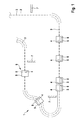
- the transport device 1 comprises a transfer line 2 and an electromagnetic drive.
- the electromagnetic drive comprises a plurality of stationary coil elements 3, which are arranged on the transfer path 2, and a plurality of permanent magnets 4, wherein in each case a permanent magnet 4 is arranged on a rotor 5.
- the individual coil elements 3 can each be individually controlled and energized to move the rotor 5 along the transfer path 2.
- the transfer section 2 can be closed linearly or circumferentially.
- the transport device 1 further comprises an individual recognition device 6, which comprises a plurality of stationary sensors 7 and a plurality of individual marking devices 8.
- the identification device 6 may comprise different sensors 7 and marking devices 8, for example RFID sensors and RFID elements, Hall sensors and permanent magnets, incremental encoder sensors and magnetic strips, or barcode sensors and barcode elements. All the sensors and marking devices according to the invention have in common that a hardware-based solution of the recognition is realized. Here, 5 purely passive elements are used on the runners, which no Need energy supply, so that the runners are simple and inexpensive.
- a possibly necessary reference travel of the rotor 5 in combination with a position detection system which detects positions of the runners on the transfer section 2, be abbreviated.
- a position detection system which detects positions of the runners on the transfer section 2
- the position detection system still reports the same positions of the rotor 5 as before switching off, it can be assumed that the runners have not been moved manually in the meantime.
- This can now be additionally verified according to the invention by a short reference run is performed, namely, until a runner 5 of one of Sensors 7 is detected and uniquely identified.
- the detected identification of the rotor 5 now agrees with the identification stored at this position before the system is switched off, the reference travel can be ended and unambiguous conditions prevail in the transport device.
- the detected identification does not match the identification stored before switching off, this means that during the switched-off state one or more runners 5 have been manually displaced.
- a longer reference journey is necessary until all runners are clearly identified.
Landscapes
- Control Of Conveyors (AREA)
- Controlling Sheets Or Webs (AREA)
Description
- Die vorliegende Erfindung betrifft eine Transportvorrichtung zum Transport von Produkten, insbesondere zur Beschickung von Verpackungsmaschinen, bei der eine Erkennung und Verfolgung von Läufern möglich ist.
- Aus der
DE 102009002606 A1 ist eine umlaufende Transportvorrichtung bekannt, welche ein verbessertes Antriebskonzept aufweist. Diese bekannte Transportvorrichtung umfasst eine umlaufende Transportstrecke, wenigstens einen Läufer und einen elektromagnetischen Antrieb mit einer Vielzahl von ortsfesten Spulenelementen und einen am Läufer angeordneten Permanentmagnet. Wenn bei derartigen Transportvorrichtungen eine relativ lange Transportstrecke vorhanden ist, auf der eine Vielzahl von Läufern bewegt wird, kann eine Überwachung der Läufer schwierig sein. Zur Steuerung des elektromagnetischen Antriebs ist es jedoch notwendig zu wissen, wo sich der jeweilige Läufer befindet. Auch ist eine Verfolgung eines Läufers und damit des durch ihn transportierten Produkts über die gesamte Transferstrecke wünschenswert. Ein derartiges System sollte jedoch möglichst einfach und sicher sein. - Weiterhin sind aus der
US 6876896 B1 und derUS 2003/0230941 A1 Transportvorrichtungen gemäß dem Oberbegriff des Anspruchs 1 bekannt. - Bei der Transportvorrichtung mit den Merkmalen des Anspruchs 1 ist eine einfache und kostengünstige Erkennung von Läufern auf einer Transferstrecke möglich. Insbesondere können zur Erkennung der Läufer dabei rein passive Elemente ohne Energieversorgung auf den Läufern verwendet werden. Die
- Erkennungsvorrichtung ist dabei unanfällig gegenüber Verschmutzung und es sind auch höhere Geschwindigkeiten von größer als 4 m/s möglich. Darüber hinaus ist die Erkennungsvorrichtung verschleißfrei. Dies wird dadurch erreicht, dass die Erkennungsvorrichtung wenigstens einen ortsfest an der Transferstrecke angeordneten Sensor und eine individuelle Markierungseinrichtung umfasst, welche vom Sensor erfassbar ist. Die Markierungseinrichtung ist dabei jeweils an einem Läufer angeordnet und individuell ausgestaltet. Somit können alle Läufer auf der Transferstrecke jederzeit eindeutig erkannt werden, wodurch auch eine Nachverfolgung des transportierten Produkts möglich ist.
- Die erfindungsgemäße Transportvorrichtung wird dadurch gekennzeichnet, dass jeder Läufer wenigstens zwei unterschiedliche individuelle Markierungseinrichtungen aufweist. Hierdurch kann eine Redundanz für eine sichere Erfassung bereitgestellt werden.
- Die Unteransprüche zeigen bevorzugte Weiterbildungen der Erfindung.
- Vorzugsweise ist eine Vielzahl von Sensoren an der Transferstrecke angeordnet. Besonders bevorzugt weisen die Sensoren dabei jeweils zueinander gleiche Abstände auf. Hierdurch kann eine mehrfache Erfassung des Läufers ermöglicht werden. Durch die Vielzahl der erhobenen Daten ist ferner auch eine sehr genaue Positionsbestimmung der Läufer möglich.
- Weiter bevorzugt umfasst die Transportvorrichtung eine Positionserfassungsvorrichtung zur Erfassung einer Position eines Läufers auf der Transferstrecke. Besonders bevorzugt ist die Positionserfassungsvorrichtung mit der erfindungsgemäßen Erkennungsvorrichtung verbunden, so dass nicht nur erfasst werden kann, an welchen Positionen sich Läufer befinden, sondern exakt bestimmt werden kann, an welcher Position sich welcher Läufer befindet, insbesondere, wenn sich die Läufer zwischen zwei Sensoren befinden.
- Gemäß einem bevorzugten Ausführungsbeispiel der Erfindung umfasst die Erkennungsvorrichtung als Sensor einen RFID-Sensor und die Markierungseinrichtung ist ein RFID-Element. Hierdurch kann eine besonders kostengünstige Erkennungsvorrichtung bereitgestellt werden.
- Vorzugsweise ist die Markierungseinrichtung derart ausgebildet, dass zusätzliche weitere optionale Daten gespeichert und/oder geändert und/oder gelöscht und/oder ausgelesen werden können.
- Gemäß einer alternativen Ausgestaltung der Erfindung ist der Sensor der Erkennungsvorrichtung ein Hall-Sensor und die individuelle Markierungseinrichtung ist ein Permanentmagnet. Diese erfindungsgemäße Erkennungsvorrichtung kann ebenfalls sehr einfach und kostengünstig bereitgestellt werden.
- Gemäß einer noch weiteren bevorzugten Alternative der Erfindung ist der Sensor der Erkennungseinrichtung ein Inkrementalgeber-Sensor und die individuelle Markierungseinrichtung umfasst mehrere Magnetstreifen von Permanentmagneten.
- Bei den Erkennungseinrichtungen, welche als individuelle Markierungseinrichtungen Permanentmagnete verwenden, sei angemerkt, dass die Permanentmagnete zur Unterscheidung vorzugsweise unterschiedliche Magnetstärken und/oder unterschiedliche Polungen aufweisen. Hierdurch kann jeweils eine individuelle Kennzeichnung jedes Läufers ermöglicht werden.
- Besonders bevorzugt wird ein Signal des Inkrementalgeber-Sensors auch der Positionserfassungsvorrichtung zugeführt. Da eine Erkennungsvorrichtung mit einem Inkrementalgeber-Sensor und Magnetstreifen auch ein sehr genaues Wegmesssystem mit einer Genauigkeit bis zu 10 µm darstellt, kann diese Information auch gezielt zur Bestimmung der exakten Position des Läufers verwendet werden. Hierdurch kann beispielsweise ein bereits vorhandenes Positionserfassungssystem noch genauer werden.
- Gemäß einer weiteren bevorzugten Ausgestaltung der Erfindung umfasst die erfindungsgemäße Erkennungseinrichtung einen Barcode-Leser als Sensor und ein Barcode-Element als individuelle Markierungseinrichtung. Auch diese Erkennungseinrichtung kann besonders einfach und kostengünstig bereitgestellt werden.
- Die Erfindung wird bevorzugt auf umlaufend geschlossenen Transferstrecken verwendet. Die Streckenführung der Transferstrecken kann dabei beliebig sein, d.h., gerade und kurvige Abschnitte in beliebiger Anordnung umfassen. Besonders bevorzugt wird die Transportvorrichtung der Erfindung in Verbindung mit einer Beschickung von Verpackungsmaschinen verwendet.
- Nachfolgend wird unter Bezugnahme auf die begleitende Zeichnung ein Ausführungsbeispiel der Erfindung im Detail beschrieben. In der Zeichnung ist:
- Figur 1
- eine schematische Darstellung einer Transportvorrichtung gemäß einem bevorzugten Ausführungsbeispiel der Erfindung.
- Wie aus
Figur 1 ersichtlich ist, umfasst die Transportvorrichtung 1 eine Transferstrecke 2 und einen elektromagnetischen Antrieb. Der elektromagnetische Antrieb umfasst eine Vielzahl von ortsfesten Spulenelementen 3, welche an der Transferstrecke 2 angeordnet sind, und eine Vielzahl von Permanentmagneten 4, wobei jeweils ein Permanentmagnet 4 an einem Läufer 5 angeordnet ist. Dabei können die einzelnen Spulenelemente 3 jeweils individuell voneinander angesteuert und bestromt werden, um die Läufer 5 entlang der Transferstrecke 2 zu bewegen. Die Transferstrecke 2 kann dabei linienförmig oder umlaufend geschlossen sein. - Die Transportvorrichtung 1 umfasst ferner eine individuelle Erkennungseinrichtung 6, welche eine Vielzahl von ortsfesten Sensoren 7 und eine Vielzahl von individuellen Markierungseinrichtungen 8 umfasst. Die Erkennungseinrichtung 6 kann dabei unterschiedlichen Sensoren 7 und Markierungseinrichtungen 8 umfassen, beispielsweise RFID-Sensoren und RFID-Elemente, Hall-Sensoren und Permanentmagnete, Inkrementalgeber-Sensoren und Magnetstreifen, oder Barcode-Sensoren und Barcode-Elemente. Allen erfindungsgemäßen Sensoren und Markierungseinrichtungen ist dabei gemeinsam, dass eine hardwarebasierte Lösung der Erkennung realisiert ist. Hierbei werden an den Läufern 5 rein passive Elemente verwendet, welche keine Energieversorgung benötigen, so dass die Läufer einfach und kostengünstig aufgebaut sind.
- Insbesondere bei der Verwendung von RFID-Sensoren und RFID-Elementen können neben der Erfassung der individuellen Markierung auch die RFID-Elemente auf den Läufern 5 während des Vorbeibewegens aktiv beschrieben und nicht nur ausgelesen werden. Auch wäre eine Speicherung eines weiteren Merkmals auf dem RFID-Element möglich. Beispielsweise könnte nicht nur die Läufer-Identifikation auf dem RFID-Element vorhanden sein, sondern ebenfalls ein weiteres Datum, welches beispielsweise für die Produktion auf dem RFID-Element gespeichert und an anderer Stelle ausgelesen und/oder abgeändert werden kann.
- Auch ist es erfindungsgemäß möglich, beispielsweise fehlerhafte Läufer 5 zu erfassen und schon vor einem eventuell auftretenden Fehler vorbeugend auszutauschen. Hierbei werden die Läufer 5 alle mit einem exakt gleichen Bewegungsprofil über eine definierte Messstrecke bewegt. In der Steuereinheit ist ein bestimmtes Profil für eine Bestromung des elektromagnetischen Antriebs hinterlegt, welches beispielsweise bei einer Inbetriebnahme ermittelt und abgespeichert wurde. Durch einen kontinuierlichen Vergleich des hinterlegten Profils mit den aktuell gemessenen Stromwerten in definierten Zeitintervallen können Rückschlüsse darauf gezogen werden, ob ein Läufer 5 einen erhöhten Strombedarf aufweist. Dies könnte beispielsweise auf ein mechanisches Problem, z.B. eine verschlissene Läuferführung, hindeuten. Erfindungsgemäß kann nun dieser Läufer 5 eindeutig bestimmt werden und gegebenenfalls ersetzt werden.
- Auch kann beispielsweise nach einem kompletten Abschalten der Transportvorrichtung eine möglicherweise notwendig Referenzfahrt der Läufer 5 in Kombination mit einem Positionserfassungssystem, welches Positionen der Läufer auf der Transferstrecke 2 erfasst, abgekürzt werden. Wenn beispielsweise nach einem Wiedereinschalten das Positionserfassungssystem noch dieselben Positionen der Läufer 5 meldet wie vor dem Ausschalten, kann angenommen werden, dass die Läufer zwischenzeitlich nicht manuell verschoben wurden. Dies kann nun erfindungsgemäß noch zusätzlich verifiziert werden, indem ein kurzer Referenzlauf ausgeführt wird, nämlich so lange, bis ein Läufer 5 von einem der Sensoren 7 detektiert wird und eindeutig identifiziert wird. Stimmt nun die detektierte Identifikation des Läufers 5 noch mit der vor dem Ausschalten des Systems gespeicherten Identifikation an dieser Position überein, kann die Referenzfahrt beendet werden und in der Transportvorrichtung herrschen eindeutige Verhältnisse. Stimmt die detektierte Identifikation jedoch nicht mit der vor dem Ausschalten gespeicherten Identifikation überein, bedeutet dies, dass während des ausgeschaltet Zustands ein oder mehrere Läufer 5 von Hand verschoben wurden. Hier ist dann eine längere Referenzfahrt notwendig, bis alle Läufer eindeutig identifiziert sind.
Claims (9)
- Transportvorrichtung zum Transport von Produkten, insbesondere zur Beschickung von Verpackungsmaschinen, umfassend:- eine Transferstrecke (2),- einen elektromagnetischen Antrieb mit einer Vielzahl von Spulenelementen (3) und einer Vielzahl von Permanentmagneten (4), wobei die Spulenelemente (3) ortsfest an der Transferstrecke (2) angeordnet sind,- eine Vielzahl von Läufern (5), welche verfahrbar an der Transferstrecke (2) angeordnet sind, wobei wenigstens jeweils ein Permanentmagnet (4) des elektromagnetischen Antriebs an einem Läufer (5) angeordnet ist,- wenigstens einen Sensor (7), welcher ortsfest an der Transferstrecke (2) angeordnet ist, und- individuelle Markierungseinrichtungen (8), welche mittels des Sensors erfassbar sind und welche zueinander jeweils unterschiedlich sind,- wobei jeweils wenigstens einer der Markierungseinrichtungen (8) an einem Läufer (5) angeordnet ist,
dadurch gekennzeichnet, dass- jeder Läufer (5) wenigstens zwei unterschiedliche, individuelle Markierungseinrichtungen (8) umfasst. - Vorrichtung nach Anspruch 1, dadurch gekennzeichnet, dass die Vorrichtung eine Vielzahl von Sensoren (7) umfasst.
- Vorrichtung nach einem der vorhergehenden Ansprüche, ferner umfassend eine Positionserfassungsvorrichtung, um eine Position der Läufer (5) auf der Transferstrecke (2) zu erfassen.
- Vorrichtung nach einem der vorhergehenden Ansprüche, dadurch gekennzeichnet, dass die individuelle Markierungseinreichung (8) derart ausgebildet ist, dass zusätzliche Daten und/oder Informationen speicherbar und/oder änderbar und/oder löschbar und/oder auslesbar sind.
- Vorrichtung nach einem der vorhergehenden Ansprüche, dadurch gekennzeichnet, dass der Sensor (7) ein RFID-Sensor ist und eine der Markierungseinrichtungen (8) ein RFID-Element ist.
- Vorrichtung nach einem der Ansprüche 1 bis 5, dadurch gekennzeichnet, dass der Sensor (7) ein Hall-Sensor ist und eine der Markierungseinrichtungen (8) ein Permanentmagnet ist.
- Vorrichtung nach einem der Ansprüche 1 bis 6, dadurch gekennzeichnet, dass der Sensor (7) ein Inkrementalgeber-Sensor ist und eine der Markierungseinrichtungen (8) streifenartige Permanentmagnete umfasst.
- Vorrichtung nach Anspruch 6 oder 7, dadurch gekennzeichnet, dass die Permanentmagnete unterschiedliche Magnetstärken und/oder unterschiedliche Polungen aufweisen.
- Vorrichtung nach einem der Ansprüche 1 bis 8, dadurch gekennzeichnet, dass der Sensor (7) ein Barcode-Leser ist und eine der Markierungseinrichtungen (8) ein Barcode-Element, insbesondere ein Aufdruck oder ein Aufkleber, ist.
Applications Claiming Priority (2)
| Application Number | Priority Date | Filing Date | Title |
|---|---|---|---|
| DE102011003682A DE102011003682A1 (de) | 2011-02-07 | 2011-02-07 | Transportvorrichtung mit Erkennungsfunktion |
| PCT/EP2012/052019 WO2012107431A1 (de) | 2011-02-07 | 2012-02-07 | Transportvorrichtung mit erkennungsfunktion |
Publications (2)
| Publication Number | Publication Date |
|---|---|
| EP2673224A1 EP2673224A1 (de) | 2013-12-18 |
| EP2673224B1 true EP2673224B1 (de) | 2015-01-14 |
Family
ID=45567016
Family Applications (1)
| Application Number | Title | Priority Date | Filing Date |
|---|---|---|---|
| EP12702827.2A Not-in-force EP2673224B1 (de) | 2011-02-07 | 2012-02-07 | Transportvorrichtung mit erkennungsfunktion |
Country Status (5)
| Country | Link |
|---|---|
| US (1) | US20130313072A1 (de) |
| EP (1) | EP2673224B1 (de) |
| CN (1) | CN103354797B (de) |
| DE (1) | DE102011003682A1 (de) |
| WO (1) | WO2012107431A1 (de) |
Cited By (8)
| Publication number | Priority date | Publication date | Assignee | Title |
|---|---|---|---|---|
| US10737403B2 (en) | 2014-04-25 | 2020-08-11 | Weber Maschinenbau Gmbh Breidenbach | Autonomously electromagnetic transport carrier of food portions |
| US11713147B2 (en) | 2019-07-30 | 2023-08-01 | Anheuser-Busch Inbev S.A. | Article picking and treating apparatus |
| US12110141B2 (en) | 2019-07-30 | 2024-10-08 | Anheuser-Busch Inbev S.A. | Packaging apparatus |
| US12162236B2 (en) | 2019-07-30 | 2024-12-10 | Anheuser-Busch Inbev S.A. | Shaping tool for secondary packages |
| US12269629B2 (en) | 2019-07-30 | 2025-04-08 | Anheuser-Busch Inbev S.A. | Packaging apparatus for secondary packages |
| US12286318B2 (en) | 2019-07-30 | 2025-04-29 | Anheuser-Busch Inbev S.A. | Denesting apparatus |
| US12415684B2 (en) | 2021-03-03 | 2025-09-16 | Provisur Technologies, Inc. | Belt conveyor for conveying foodstuff products |
| US12466100B2 (en) | 2021-03-03 | 2025-11-11 | Provisur Technologies, Inc. | Food-processing system |
Families Citing this family (29)
| Publication number | Priority date | Publication date | Assignee | Title |
|---|---|---|---|---|
| EP2746201B1 (de) * | 2012-12-21 | 2015-09-30 | Robert Bosch Gmbh | Vorrichtung und Verfahren zur Förderung von Trägern in einer Maschine |
| DE102013218403A1 (de) * | 2013-09-13 | 2015-03-19 | Krones Ag | Vorrichtung und Verfahren zum Transport von Behältern in einer Behälterbehandlungsanlage |
| US9649640B2 (en) * | 2014-04-16 | 2017-05-16 | Flsmidth A/S | Methods and apparatus for the continuous monitoring of wear in flotation circuits |
| DE102014108299B4 (de) * | 2014-06-12 | 2023-04-27 | Airbus Operations Gmbh | Vorrichtung und Verfahren zur Positionserfassung einer beweglichen Transporteinheit |
| EP3016136B1 (de) * | 2014-10-27 | 2021-07-21 | Robert Bosch GmbH | Transportsystem mit magnetisch angetriebenen Transportelementen und entsprechendes Transportverfahren |
| DE102014117200A1 (de) | 2014-11-24 | 2016-05-25 | Beckhoff Automation Gmbh | Positionserfassungssystem |
| US9611107B2 (en) | 2014-12-08 | 2017-04-04 | Rockwell Automation Technologies, Inc. | Linear drive transport system and method |
| CN105469011B (zh) * | 2014-12-10 | 2018-09-28 | 张丽玉 | 磁条码、磁条码识别装置与其使用方法及磁条码充磁装置 |
| FR3030051A1 (fr) * | 2014-12-12 | 2016-06-17 | Commissariat Energie Atomique | Procede et systeme de localisation d'un objet instrumente transporte le long d'un parcours par une machine de convoi |
| CN105057219B (zh) | 2015-07-22 | 2018-11-27 | 杭州亚美利嘉科技有限公司 | 包裹分捡系统及方法 |
| CN105472903A (zh) * | 2015-12-14 | 2016-04-06 | 天津华迈科技有限公司 | 一种smt贴片输送组件 |
| DE102016102372A1 (de) * | 2016-02-11 | 2017-08-17 | Inotec Gmbh Maschinenentwicklung Und Vertrieb | Vorrichtung zum Trennen von einzelnen über Drehstellen voneinander getrennten Würsten |
| FR3051717A1 (fr) * | 2016-05-27 | 2017-12-01 | Mgi Digital Tech | Dispositif et procede de transport de substrats dans une machine d'impression |
| AT518733B1 (de) * | 2016-05-31 | 2018-05-15 | B & R Ind Automation Gmbh | Verfahren zum Betreiben eines Langstatorlinearmotors |
| AT518734B1 (de) | 2016-05-31 | 2018-05-15 | B & R Ind Automation Gmbh | Verfahren zum Betreiben eines Langstatorlinearmotors |
| DE102016111357A1 (de) * | 2016-06-10 | 2017-12-14 | Weber Maschinenbau Gmbh Breidenbach | Vorrichtung zum Transport von Objekten |
| CN107160397B (zh) | 2017-06-09 | 2023-07-18 | 浙江立镖机器人有限公司 | 机器人行走的模块地标、地标及其机器人 |
| US10906748B2 (en) * | 2017-08-09 | 2021-02-02 | Rockwell Automation Technologies, Inc. | Method and apparatus for identifying a mover on a closed track |
| EP4270241A3 (de) | 2017-08-15 | 2024-01-17 | Tompkins Robotics, Inc. | Sortiersystem und -verfahren mit mobilen sortierplattformen |
| US10899542B2 (en) | 2017-08-15 | 2021-01-26 | Tompkins International | Mobile sorter platforms and method for sorting articles |
| DE102018118814B4 (de) * | 2018-08-02 | 2024-07-18 | Beckhoff Automation Gmbh | Verfahren zum Identifizieren eines Schlittens eines linearen Transportsystems |
| EP3653428A1 (de) * | 2018-11-19 | 2020-05-20 | B&R Industrial Automation GmbH | Verfahren zum sicheren überwachen der funktion eines langstatorlinearmotors |
| CN113460709A (zh) * | 2020-03-30 | 2021-10-01 | 住友重机械工业株式会社 | 线性马达输送系统及其运用方法 |
| JP2021160841A (ja) * | 2020-03-30 | 2021-10-11 | 住友重機械工業株式会社 | リニアモータ搬送システム |
| DE102020205002A1 (de) * | 2020-04-21 | 2021-10-21 | Robert Bosch Gesellschaft mit beschränkter Haftung | Transportsystem |
| EP3926424A1 (de) * | 2020-06-18 | 2021-12-22 | Beckhoff Automation GmbH | Verfahren zum betreiben eines planarantriebssystems und planarantriebssystem |
| CN113351506B (zh) * | 2021-08-04 | 2022-05-03 | 常州微亿智造科技有限公司 | 手机后盖高速检测设备 |
| DE102021122721A1 (de) * | 2021-09-02 | 2023-03-02 | Homag Gmbh | Fördervorrichtung mit unabhängig bewegbaren Nocken zur Zuführung und/oder Ausrichtung von Werkstücken |
| EP4560329A1 (de) * | 2023-11-21 | 2025-05-28 | Schneider Electric Industries Sas | Systemüberwachungsverfahren und -vorrichtung in einem mehrträgersystem, mehrträgersystem |
Family Cites Families (23)
| Publication number | Priority date | Publication date | Assignee | Title |
|---|---|---|---|---|
| DE19524485A1 (de) * | 1995-07-05 | 1997-01-09 | Kumeth Siegmund | Transportsystem |
| DE19532281A1 (de) * | 1995-09-01 | 1997-03-06 | Guehring Egon | Transfersystem |
| US5980193A (en) * | 1996-09-18 | 1999-11-09 | Magnetic Bearing Technologies, Inc. | Magnetically levitated robot and method of increasing levitation force |
| US6191507B1 (en) * | 1997-05-02 | 2001-02-20 | Ats Automation Tooling Systems Inc. | Modular conveyor system having multiple moving elements under independent control |
| ES2149659B1 (es) * | 1997-05-30 | 2001-03-16 | Investronica Sist S S A | Sistema aereo para transporte, almacenamiento, clasificacion y control de productos ligeros. |
| JPH1159901A (ja) * | 1997-08-11 | 1999-03-02 | Murata Mach Ltd | キャリヤー移動装置 |
| US6876896B1 (en) * | 1999-04-26 | 2005-04-05 | Ab Tetrapak | Variable motion system and method |
| US7134258B2 (en) * | 2001-12-05 | 2006-11-14 | R.A. Jones & Co. Inc. | Packaging apparatus and methods |
| EP1547230B1 (de) * | 2002-06-05 | 2017-03-22 | Jacobs Automation, Inc. | Gesteuertes bewegungssystem |
| US7380654B2 (en) * | 2002-07-26 | 2008-06-03 | Abbott Laboratories | Conveyor track drive |
| NL1024150C2 (nl) * | 2003-08-22 | 2005-02-23 | Stork Pmt | Inrichting en werkwijze voor het verwerken van slachtdieren en/of delen daarvan voorzien van een transportsysteem. |
| US7478749B2 (en) * | 2004-05-17 | 2009-01-20 | Thermal Solutions, Inc. | Food preparation system |
| EP1635443A1 (de) * | 2004-09-10 | 2006-03-15 | Motor Operate Systems B.V. | Modulare Schienen- und Führungssektionen für einen Linearmotor |
| DE102007014876B4 (de) * | 2007-03-26 | 2010-04-08 | Kba-Metronic Aktiengesellschaft | Transportsystem |
| ITMI20072254A1 (it) * | 2007-11-30 | 2009-06-01 | Dachi S R L | "impianto di identificazione, trasporto ed indirizzamento automatico di campioni di materiale biologico" |
| WO2009148942A2 (en) * | 2008-06-03 | 2009-12-10 | Teradyne, Inc. | Processing storage devices |
| EP2182627B1 (de) * | 2008-10-31 | 2012-02-01 | Robert Bosch GmbH | Verfahren und Vorrichtung zur Steuerung eines linearen Bewegungssystems |
| NL2002441C2 (nl) * | 2009-01-22 | 2010-07-26 | Stork Pmt | Transportsysteem. |
| DE102009002606A1 (de) | 2009-04-23 | 2010-10-28 | Robert Bosch Gmbh | Umlaufende Transportvorrichtung mit verbessertem Antriebskonzept |
| EP2439772B1 (de) * | 2009-06-02 | 2015-04-08 | Murata Machinery, Ltd. | Fördersystem mit endlosantriebsmedium und förderverfahren |
| DE102009033183A1 (de) * | 2009-07-13 | 2011-01-27 | Ief Werner Gmbh | Transportsystem für eine Produktionsanlage |
| DE102009041483A1 (de) * | 2009-09-14 | 2011-03-31 | Siemens Aktiengesellschaft | Lagegebersystem |
| DE202009015916U1 (de) * | 2009-11-23 | 2010-03-11 | Noell Mobile Systems Gmbh | Sensorsystem für Förderanlagen mit Linear-Synchronmotoren-Antrieb und Förderanlage |
-
2011
- 2011-02-07 DE DE102011003682A patent/DE102011003682A1/de not_active Withdrawn
-
2012
- 2012-02-07 WO PCT/EP2012/052019 patent/WO2012107431A1/de not_active Ceased
- 2012-02-07 CN CN201280007700.2A patent/CN103354797B/zh not_active Expired - Fee Related
- 2012-02-07 EP EP12702827.2A patent/EP2673224B1/de not_active Not-in-force
- 2012-02-07 US US13/984,280 patent/US20130313072A1/en not_active Abandoned
Cited By (8)
| Publication number | Priority date | Publication date | Assignee | Title |
|---|---|---|---|---|
| US10737403B2 (en) | 2014-04-25 | 2020-08-11 | Weber Maschinenbau Gmbh Breidenbach | Autonomously electromagnetic transport carrier of food portions |
| US11713147B2 (en) | 2019-07-30 | 2023-08-01 | Anheuser-Busch Inbev S.A. | Article picking and treating apparatus |
| US12110141B2 (en) | 2019-07-30 | 2024-10-08 | Anheuser-Busch Inbev S.A. | Packaging apparatus |
| US12162236B2 (en) | 2019-07-30 | 2024-12-10 | Anheuser-Busch Inbev S.A. | Shaping tool for secondary packages |
| US12269629B2 (en) | 2019-07-30 | 2025-04-08 | Anheuser-Busch Inbev S.A. | Packaging apparatus for secondary packages |
| US12286318B2 (en) | 2019-07-30 | 2025-04-29 | Anheuser-Busch Inbev S.A. | Denesting apparatus |
| US12415684B2 (en) | 2021-03-03 | 2025-09-16 | Provisur Technologies, Inc. | Belt conveyor for conveying foodstuff products |
| US12466100B2 (en) | 2021-03-03 | 2025-11-11 | Provisur Technologies, Inc. | Food-processing system |
Also Published As
| Publication number | Publication date |
|---|---|
| CN103354797B (zh) | 2016-05-18 |
| WO2012107431A1 (de) | 2012-08-16 |
| US20130313072A1 (en) | 2013-11-28 |
| CN103354797A (zh) | 2013-10-16 |
| DE102011003682A1 (de) | 2012-08-09 |
| EP2673224A1 (de) | 2013-12-18 |
Similar Documents
| Publication | Publication Date | Title |
|---|---|---|
| EP2673224B1 (de) | Transportvorrichtung mit erkennungsfunktion | |
| EP3376166B1 (de) | Verfahren zur bestimmung der absolutposition eines läufers eines linearmotors | |
| DE102008006305B4 (de) | Verfahren und System | |
| EP2831549B1 (de) | Positionserfassungsvorrichtung und verfahren zum erfassen einer position eines beweglichen elements einer antriebsvorrichtung | |
| EP2533018B1 (de) | Lineares Wegmesssystem | |
| EP3955436A1 (de) | Linearmotorsystem und betriebsverfahren für ein solches | |
| EP2672276B1 (de) | Verwendung einer elektromagnetischen Geschwindigkeitsänderungsvorrichtung, wie Linearmotor oder/und Wirbelstrombremse, zur Geschwindigkeitsmessung | |
| DE102009020183B4 (de) | Bewegungsfahrzeugsystem und Verfahren zum Erfassen der Position eines Bewegungsfahrzeugs | |
| WO2011134823A2 (de) | Inkrementelles multipositions-erfassungssystem für ein umlaufendes elektromagnetisches transfersystem | |
| EP2568582B1 (de) | Elektrische Maschine | |
| DE102010041837B4 (de) | Verfahren und Vorrichtung zur Steuerung von Transportmitteln in einem Materialtransportsystem einer Rollendruckmaschine | |
| EP2568261A2 (de) | Positions-/Wegmesssystem | |
| WO2020104454A1 (de) | Verfahren zum sicheren überwachen der funktion einer elektromagnetischen transporteinrichtung | |
| DE102010028017A1 (de) | Bewegtfahrzeugsystem und Verfahren zum Erfassen einer Position eines sich bewegenden Fahrzeugs | |
| DE102017119300A1 (de) | Vorrichtung und Verfahren zur Ermittlung des Verschleisszustandes einer Kette | |
| EP3325211B1 (de) | Werkstückträger mit einem codeelement für eine fertigungsanlage | |
| EP2159549A1 (de) | Vorrichtung zur Messung der Relativposition zwischen einer Massverkörperung und einem Lesekopf | |
| WO2006134007A2 (de) | Fördersystem, insbesondere flughafengepäckfördersystem | |
| EP2869035B1 (de) | Positionsmesssystem und Regelungsverfahren für verkettete Linearmotoren | |
| EP2325039A2 (de) | Sensorsystem für Förderanlagen mit Linear-Synchron-Antrieb und Förderanlage | |
| EP2430401B1 (de) | Positionserfassungsanordnung für ein umlaufendes transfersystem | |
| DE10320759B4 (de) | Transportsystem mit Gebern zur Lageerfassung in einer bedruckstoffverarbeitenden Maschine | |
| CH703919A1 (de) | Verfahren zum Betrieb einer Transportvorrichtung sowie Transportvorrichtung zur Durchführung des Verfahrens. | |
| DE102018203409A1 (de) | Linearbewegungsvorrichtung und Verfahren | |
| DE102016206905B4 (de) | Linearantriebssystem und Verfahren zur Ermittlung von zwei Positionen zweier Messelemente, die längs eines Bewegungswegs eines Linearantriebssystems bewegt werden |
Legal Events
| Date | Code | Title | Description |
|---|---|---|---|
| PUAI | Public reference made under article 153(3) epc to a published international application that has entered the european phase |
Free format text: ORIGINAL CODE: 0009012 |
|
| 17P | Request for examination filed |
Effective date: 20130909 |
|
| AK | Designated contracting states |
Kind code of ref document: A1 Designated state(s): AL AT BE BG CH CY CZ DE DK EE ES FI FR GB GR HR HU IE IS IT LI LT LU LV MC MK MT NL NO PL PT RO RS SE SI SK SM TR |
|
| DAX | Request for extension of the european patent (deleted) | ||
| GRAP | Despatch of communication of intention to grant a patent |
Free format text: ORIGINAL CODE: EPIDOSNIGR1 |
|
| INTG | Intention to grant announced |
Effective date: 20141007 |
|
| GRAS | Grant fee paid |
Free format text: ORIGINAL CODE: EPIDOSNIGR3 |
|
| GRAA | (expected) grant |
Free format text: ORIGINAL CODE: 0009210 |
|
| AK | Designated contracting states |
Kind code of ref document: B1 Designated state(s): AL AT BE BG CH CY CZ DE DK EE ES FI FR GB GR HR HU IE IS IT LI LT LU LV MC MK MT NL NO PL PT RO RS SE SI SK SM TR |
|
| REG | Reference to a national code |
Ref country code: GB Ref legal event code: FG4D Free format text: NOT ENGLISH |
|
| REG | Reference to a national code |
Ref country code: CH Ref legal event code: EP |
|
| REG | Reference to a national code |
Ref country code: IE Ref legal event code: FG4D Free format text: LANGUAGE OF EP DOCUMENT: GERMAN |
|
| REG | Reference to a national code |
Ref country code: AT Ref legal event code: REF Ref document number: 706915 Country of ref document: AT Kind code of ref document: T Effective date: 20150215 |
|
| REG | Reference to a national code |
Ref country code: DE Ref legal event code: R096 Ref document number: 502012002108 Country of ref document: DE Effective date: 20150226 |
|
| REG | Reference to a national code |
Ref country code: NL Ref legal event code: VDEP Effective date: 20150114 |
|
| REG | Reference to a national code |
Ref country code: LT Ref legal event code: MG4D |
|
| PG25 | Lapsed in a contracting state [announced via postgrant information from national office to epo] |
Ref country code: BE Free format text: LAPSE BECAUSE OF NON-PAYMENT OF DUE FEES Effective date: 20150228 |
|
| PG25 | Lapsed in a contracting state [announced via postgrant information from national office to epo] |
Ref country code: SE Free format text: LAPSE BECAUSE OF FAILURE TO SUBMIT A TRANSLATION OF THE DESCRIPTION OR TO PAY THE FEE WITHIN THE PRESCRIBED TIME-LIMIT Effective date: 20150114 Ref country code: LT Free format text: LAPSE BECAUSE OF FAILURE TO SUBMIT A TRANSLATION OF THE DESCRIPTION OR TO PAY THE FEE WITHIN THE PRESCRIBED TIME-LIMIT Effective date: 20150114 Ref country code: NO Free format text: LAPSE BECAUSE OF FAILURE TO SUBMIT A TRANSLATION OF THE DESCRIPTION OR TO PAY THE FEE WITHIN THE PRESCRIBED TIME-LIMIT Effective date: 20150414 Ref country code: BG Free format text: LAPSE BECAUSE OF FAILURE TO SUBMIT A TRANSLATION OF THE DESCRIPTION OR TO PAY THE FEE WITHIN THE PRESCRIBED TIME-LIMIT Effective date: 20150414 Ref country code: HR Free format text: LAPSE BECAUSE OF FAILURE TO SUBMIT A TRANSLATION OF THE DESCRIPTION OR TO PAY THE FEE WITHIN THE PRESCRIBED TIME-LIMIT Effective date: 20150114 Ref country code: ES Free format text: LAPSE BECAUSE OF FAILURE TO SUBMIT A TRANSLATION OF THE DESCRIPTION OR TO PAY THE FEE WITHIN THE PRESCRIBED TIME-LIMIT Effective date: 20150114 Ref country code: FI Free format text: LAPSE BECAUSE OF FAILURE TO SUBMIT A TRANSLATION OF THE DESCRIPTION OR TO PAY THE FEE WITHIN THE PRESCRIBED TIME-LIMIT Effective date: 20150114 |
|
| PG25 | Lapsed in a contracting state [announced via postgrant information from national office to epo] |
Ref country code: GR Free format text: LAPSE BECAUSE OF FAILURE TO SUBMIT A TRANSLATION OF THE DESCRIPTION OR TO PAY THE FEE WITHIN THE PRESCRIBED TIME-LIMIT Effective date: 20150415 Ref country code: LV Free format text: LAPSE BECAUSE OF FAILURE TO SUBMIT A TRANSLATION OF THE DESCRIPTION OR TO PAY THE FEE WITHIN THE PRESCRIBED TIME-LIMIT Effective date: 20150114 Ref country code: NL Free format text: LAPSE BECAUSE OF FAILURE TO SUBMIT A TRANSLATION OF THE DESCRIPTION OR TO PAY THE FEE WITHIN THE PRESCRIBED TIME-LIMIT Effective date: 20150114 Ref country code: PL Free format text: LAPSE BECAUSE OF FAILURE TO SUBMIT A TRANSLATION OF THE DESCRIPTION OR TO PAY THE FEE WITHIN THE PRESCRIBED TIME-LIMIT Effective date: 20150114 Ref country code: RS Free format text: LAPSE BECAUSE OF FAILURE TO SUBMIT A TRANSLATION OF THE DESCRIPTION OR TO PAY THE FEE WITHIN THE PRESCRIBED TIME-LIMIT Effective date: 20150114 Ref country code: IS Free format text: LAPSE BECAUSE OF FAILURE TO SUBMIT A TRANSLATION OF THE DESCRIPTION OR TO PAY THE FEE WITHIN THE PRESCRIBED TIME-LIMIT Effective date: 20150514 |
|
| REG | Reference to a national code |
Ref country code: DE Ref legal event code: R097 Ref document number: 502012002108 Country of ref document: DE |
|
| PG25 | Lapsed in a contracting state [announced via postgrant information from national office to epo] |
Ref country code: SK Free format text: LAPSE BECAUSE OF FAILURE TO SUBMIT A TRANSLATION OF THE DESCRIPTION OR TO PAY THE FEE WITHIN THE PRESCRIBED TIME-LIMIT Effective date: 20150114 Ref country code: RO Free format text: LAPSE BECAUSE OF FAILURE TO SUBMIT A TRANSLATION OF THE DESCRIPTION OR TO PAY THE FEE WITHIN THE PRESCRIBED TIME-LIMIT Effective date: 20150114 Ref country code: EE Free format text: LAPSE BECAUSE OF FAILURE TO SUBMIT A TRANSLATION OF THE DESCRIPTION OR TO PAY THE FEE WITHIN THE PRESCRIBED TIME-LIMIT Effective date: 20150114 Ref country code: DK Free format text: LAPSE BECAUSE OF FAILURE TO SUBMIT A TRANSLATION OF THE DESCRIPTION OR TO PAY THE FEE WITHIN THE PRESCRIBED TIME-LIMIT Effective date: 20150114 Ref country code: MC Free format text: LAPSE BECAUSE OF FAILURE TO SUBMIT A TRANSLATION OF THE DESCRIPTION OR TO PAY THE FEE WITHIN THE PRESCRIBED TIME-LIMIT Effective date: 20150114 Ref country code: CZ Free format text: LAPSE BECAUSE OF FAILURE TO SUBMIT A TRANSLATION OF THE DESCRIPTION OR TO PAY THE FEE WITHIN THE PRESCRIBED TIME-LIMIT Effective date: 20150114 |
|
| REG | Reference to a national code |
Ref country code: IE Ref legal event code: MM4A |
|
| PLBE | No opposition filed within time limit |
Free format text: ORIGINAL CODE: 0009261 |
|
| STAA | Information on the status of an ep patent application or granted ep patent |
Free format text: STATUS: NO OPPOSITION FILED WITHIN TIME LIMIT |
|
| 26N | No opposition filed |
Effective date: 20151015 |
|
| PG25 | Lapsed in a contracting state [announced via postgrant information from national office to epo] |
Ref country code: IE Free format text: LAPSE BECAUSE OF NON-PAYMENT OF DUE FEES Effective date: 20150207 |
|
| REG | Reference to a national code |
Ref country code: FR Ref legal event code: PLFP Year of fee payment: 5 |
|
| PG25 | Lapsed in a contracting state [announced via postgrant information from national office to epo] |
Ref country code: SI Free format text: LAPSE BECAUSE OF FAILURE TO SUBMIT A TRANSLATION OF THE DESCRIPTION OR TO PAY THE FEE WITHIN THE PRESCRIBED TIME-LIMIT Effective date: 20150114 |
|
| GBPC | Gb: european patent ceased through non-payment of renewal fee |
Effective date: 20160207 |
|
| PG25 | Lapsed in a contracting state [announced via postgrant information from national office to epo] |
Ref country code: MT Free format text: LAPSE BECAUSE OF FAILURE TO SUBMIT A TRANSLATION OF THE DESCRIPTION OR TO PAY THE FEE WITHIN THE PRESCRIBED TIME-LIMIT Effective date: 20150114 |
|
| PG25 | Lapsed in a contracting state [announced via postgrant information from national office to epo] |
Ref country code: GB Free format text: LAPSE BECAUSE OF NON-PAYMENT OF DUE FEES Effective date: 20160207 |
|
| REG | Reference to a national code |
Ref country code: FR Ref legal event code: PLFP Year of fee payment: 6 |
|
| PG25 | Lapsed in a contracting state [announced via postgrant information from national office to epo] |
Ref country code: HU Free format text: LAPSE BECAUSE OF FAILURE TO SUBMIT A TRANSLATION OF THE DESCRIPTION OR TO PAY THE FEE WITHIN THE PRESCRIBED TIME-LIMIT; INVALID AB INITIO Effective date: 20120207 Ref country code: SM Free format text: LAPSE BECAUSE OF FAILURE TO SUBMIT A TRANSLATION OF THE DESCRIPTION OR TO PAY THE FEE WITHIN THE PRESCRIBED TIME-LIMIT Effective date: 20150114 |
|
| PG25 | Lapsed in a contracting state [announced via postgrant information from national office to epo] |
Ref country code: CY Free format text: LAPSE BECAUSE OF FAILURE TO SUBMIT A TRANSLATION OF THE DESCRIPTION OR TO PAY THE FEE WITHIN THE PRESCRIBED TIME-LIMIT Effective date: 20150114 |
|
| PG25 | Lapsed in a contracting state [announced via postgrant information from national office to epo] |
Ref country code: PT Free format text: LAPSE BECAUSE OF FAILURE TO SUBMIT A TRANSLATION OF THE DESCRIPTION OR TO PAY THE FEE WITHIN THE PRESCRIBED TIME-LIMIT Effective date: 20150514 |
|
| PG25 | Lapsed in a contracting state [announced via postgrant information from national office to epo] |
Ref country code: TR Free format text: LAPSE BECAUSE OF FAILURE TO SUBMIT A TRANSLATION OF THE DESCRIPTION OR TO PAY THE FEE WITHIN THE PRESCRIBED TIME-LIMIT Effective date: 20150114 |
|
| PG25 | Lapsed in a contracting state [announced via postgrant information from national office to epo] |
Ref country code: LU Free format text: LAPSE BECAUSE OF NON-PAYMENT OF DUE FEES Effective date: 20150207 |
|
| REG | Reference to a national code |
Ref country code: FR Ref legal event code: PLFP Year of fee payment: 7 |
|
| REG | Reference to a national code |
Ref country code: AT Ref legal event code: MM01 Ref document number: 706915 Country of ref document: AT Kind code of ref document: T Effective date: 20170207 |
|
| PG25 | Lapsed in a contracting state [announced via postgrant information from national office to epo] |
Ref country code: AT Free format text: LAPSE BECAUSE OF NON-PAYMENT OF DUE FEES Effective date: 20170207 |
|
| PG25 | Lapsed in a contracting state [announced via postgrant information from national office to epo] |
Ref country code: MK Free format text: LAPSE BECAUSE OF FAILURE TO SUBMIT A TRANSLATION OF THE DESCRIPTION OR TO PAY THE FEE WITHIN THE PRESCRIBED TIME-LIMIT Effective date: 20150114 |
|
| PG25 | Lapsed in a contracting state [announced via postgrant information from national office to epo] |
Ref country code: AL Free format text: LAPSE BECAUSE OF FAILURE TO SUBMIT A TRANSLATION OF THE DESCRIPTION OR TO PAY THE FEE WITHIN THE PRESCRIBED TIME-LIMIT Effective date: 20150114 |
|
| REG | Reference to a national code |
Ref country code: DE Ref legal event code: R082 Ref document number: 502012002108 Country of ref document: DE Representative=s name: DREISS PATENTANWAELTE PARTG MBB, DE Ref country code: DE Ref legal event code: R081 Ref document number: 502012002108 Country of ref document: DE Owner name: SYNTEGON TECHNOLOGY GMBH, DE Free format text: FORMER OWNER: ROBERT BOSCH GMBH, 70469 STUTTGART, DE Ref country code: DE Ref legal event code: R081 Ref document number: 502012002108 Country of ref document: DE Owner name: SYNTEGON TECHNOLOGY GMBH, DE Free format text: FORMER OWNER: ROBERT BOSCH PACKAGING TECHNOLOGY GMBH, 71332 WAIBLINGEN, DE |
|
| REG | Reference to a national code |
Ref country code: CH Ref legal event code: PUE Owner name: SYNTEGON TECHNOLOGY GMBH, DE Free format text: FORMER OWNER: ROBERT BOSCH GMBH, DE |
|
| PGFP | Annual fee paid to national office [announced via postgrant information from national office to epo] |
Ref country code: FR Payment date: 20210218 Year of fee payment: 10 Ref country code: CH Payment date: 20210222 Year of fee payment: 10 Ref country code: IT Payment date: 20210226 Year of fee payment: 10 |
|
| PGFP | Annual fee paid to national office [announced via postgrant information from national office to epo] |
Ref country code: DE Payment date: 20210223 Year of fee payment: 10 |
|
| REG | Reference to a national code |
Ref country code: DE Ref legal event code: R119 Ref document number: 502012002108 Country of ref document: DE |
|
| REG | Reference to a national code |
Ref country code: CH Ref legal event code: PL |
|
| PG25 | Lapsed in a contracting state [announced via postgrant information from national office to epo] |
Ref country code: FR Free format text: LAPSE BECAUSE OF NON-PAYMENT OF DUE FEES Effective date: 20220228 |
|
| PG25 | Lapsed in a contracting state [announced via postgrant information from national office to epo] |
Ref country code: LI Free format text: LAPSE BECAUSE OF NON-PAYMENT OF DUE FEES Effective date: 20220228 Ref country code: DE Free format text: LAPSE BECAUSE OF NON-PAYMENT OF DUE FEES Effective date: 20220901 Ref country code: CH Free format text: LAPSE BECAUSE OF NON-PAYMENT OF DUE FEES Effective date: 20220228 |
|
| PG25 | Lapsed in a contracting state [announced via postgrant information from national office to epo] |
Ref country code: IT Free format text: LAPSE BECAUSE OF NON-PAYMENT OF DUE FEES Effective date: 20220207 |