EP2673445B1 - Système de volets de régulation thermique - Google Patents
Système de volets de régulation thermique Download PDFInfo
- Publication number
- EP2673445B1 EP2673445B1 EP12702257.2A EP12702257A EP2673445B1 EP 2673445 B1 EP2673445 B1 EP 2673445B1 EP 12702257 A EP12702257 A EP 12702257A EP 2673445 B1 EP2673445 B1 EP 2673445B1
- Authority
- EP
- European Patent Office
- Prior art keywords
- shutters
- shutter
- shutter system
- seal
- blades
- Prior art date
- Legal status (The legal status is an assumption and is not a legal conclusion. Google has not performed a legal analysis and makes no representation as to the accuracy of the status listed.)
- Active
Links
Images



Classifications
-
- E—FIXED CONSTRUCTIONS
- E06—DOORS, WINDOWS, SHUTTERS, OR ROLLER BLINDS IN GENERAL; LADDERS
- E06B—FIXED OR MOVABLE CLOSURES FOR OPENINGS IN BUILDINGS, VEHICLES, FENCES OR LIKE ENCLOSURES IN GENERAL, e.g. DOORS, WINDOWS, BLINDS, GATES
- E06B9/00—Screening or protective devices for wall or similar openings, with or without operating or securing mechanisms; Closures of similar construction
- E06B9/24—Screens or other constructions affording protection against light, especially against sunshine; Similar screens for privacy or appearance; Slat blinds
- E06B9/26—Lamellar or like blinds, e.g. venetian blinds
- E06B9/28—Lamellar or like blinds, e.g. venetian blinds with horizontal lamellae, e.g. non-liftable
- E06B9/30—Lamellar or like blinds, e.g. venetian blinds with horizontal lamellae, e.g. non-liftable liftable
- E06B9/302—Lamellar or like blinds, e.g. venetian blinds with horizontal lamellae, e.g. non-liftable liftable without ladder-tape, e.g. with lazy-tongs, with screw spindle
-
- E—FIXED CONSTRUCTIONS
- E05—LOCKS; KEYS; WINDOW OR DOOR FITTINGS; SAFES
- E05F—DEVICES FOR MOVING WINGS INTO OPEN OR CLOSED POSITION; CHECKS FOR WINGS; WING FITTINGS NOT OTHERWISE PROVIDED FOR, CONCERNED WITH THE FUNCTIONING OF THE WING
- E05F15/00—Power-operated mechanisms for wings
- E05F15/70—Power-operated mechanisms for wings with automatic actuation
-
- E—FIXED CONSTRUCTIONS
- E06—DOORS, WINDOWS, SHUTTERS, OR ROLLER BLINDS IN GENERAL; LADDERS
- E06B—FIXED OR MOVABLE CLOSURES FOR OPENINGS IN BUILDINGS, VEHICLES, FENCES OR LIKE ENCLOSURES IN GENERAL, e.g. DOORS, WINDOWS, BLINDS, GATES
- E06B7/00—Special arrangements or measures in connection with doors or windows
- E06B7/02—Special arrangements or measures in connection with doors or windows for providing ventilation, e.g. through double windows; Arrangement of ventilation roses
- E06B7/08—Louvre doors, windows or grilles
- E06B7/084—Louvre doors, windows or grilles with rotatable lamellae
- E06B7/086—Louvre doors, windows or grilles with rotatable lamellae interconnected for concurrent movement
- E06B7/094—Louvre doors, windows or grilles with rotatable lamellae interconnected for concurrent movement operable in sequence; characterised by additional independent movement
Definitions
- the present invention relates to a thermal shutter system, for example for windows.
- WO2009/100861 discloses a louver rotating mechanism for louvers of a sectional covering for architectural openings which is adapted to rotate the louvers between an open position and a closed position. In the open position, the louvers are in generally parallel planes, and in the closed position, the louvers are generally in a common plane.
- the rotating mechanism includes a slot and gate system.
- DE202006018968 relates to a louver window for installation in facades and comprising lamellar elements in vertical or inclined surfaces and which open by turning in the longitudinal axis thereof.
- a thermal shutter system comprising a plurality of elongate shutters, the shutters being mounted for rotation about the elongate direction thereof and being mounted for movement in a direction substantially perpendicular to the elongate direction, wherein the system further includes a pick and place drive mechanism constructed to move each shutter independently of the other shutter or shutters, the pick and place drive mechanism including a sensor constructed to uniquely identify each shutter of the system.
- the shutters may be arranged in pairs of subsidiary shutters positioned end-to-end.
- the subsidiary shutters of each pair may be mounted for independent rotation, but simultaneous movement perpendicular to the elongate direction.
- the shutters may be mounted within a frame.
- the frame may incorporate a seal for sealing against a surface to which the frame is secured.
- a seal such as a brush seal or an elastomeric seal, may be provided between the shutters and the frame and/or between adjacent shutters.
- the shutters may be mounted for rotation about an axis positioned adjacent to a longitudinal edge of the shutter.
- the axis may be positioned within the shutter.
- the shutters may be arranged in planes offset from the axis about which they are rotatable.
- the shutters may be rotatable to two alternative closed configurations, one in which the ends of the shutters abut against a seal and another in which the ends of the shutters are spaced from the seal.
- the shutters may be substantially rectangular.
- the shutter blades may be opaque, translucent or transparent.
- the shutters may be made of or filled with a thermal insulation material. However, if used primarily as a sun shade it is not necessary for the shutter blades to be made of or filled with a thermal insulation material. If desired, the shutter blades may be provided, at least on one face thereof, with a solar panel so as to generate all or part of the energy required for the thermal shutter system to function.
- At least one face of at least one of the shutters may be made of or provided with a reflective material.
- the shutters may be mounted on a plurality of linear members, for example extending within the frame.
- the shutters may be mounted for rotation and for movement relative to the linear members.
- the sensor may be an optical sensor adapted to recognise a visual code, such as a unique identification code, provided on each shutter.
- Means may be provided for recording the elevation and degree of rotation of each shutter.
- Such means may include a mechanism for controlling the elevation and degree of rotation of each shutter.
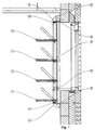
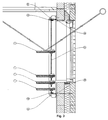
- the thermal shutter system shown in Figures 1 to 4 is provided over an internal face of an opening, such as a window, in a building and comprises a plurality of shutter blades 1 which are mounted within a frame 3.
- the frame 3 may be secured to an internal face of a building by way of a seal 9 in order to make the shutter system relatively air-tight.
- the thermal shutter system may be provided externally of a building. For example, in hot climates it may be preferable to mount the thermal shutter system externally of a building in order that it can act as a solar shade and decrease the cooling load within the building.
- the shutter blades 1 are substantially rectangular and are each mounted so as to be pivotable about a substantially horizontal axis positioned adjacent to a longitudinal edge, but within, the blade. However, it will be apparent that other pivotal mounting arrangements are possible. It will also be apparent that the shutter blades could have other configurations, such as curved, and that the pivot axes of the shutter blades could be upright rather than horizontal. The following description, however, relates to the pivot axes of the shutter blades 1 being in a horizontal configuration. Figure 1 shows the blades in several alternative positions, namely, substantially horizontal, substantially vertical and inclined to both the horizontal and the vertical.
- the shutter blades 1 are made of or filled with a thermal insulation material in order to provide thermal efficiency.
- the shutter blades may incorporate one or more vacuum insulating panels (VIPs).
- VIPs vacuum insulating panels
- the shutter blades may be opaque, translucent or transparent. If used primarily as a sun shade it is not necessary for the shutter blades to be made of or filled with a thermal insulation material. If desired, the shutter blades may be provided, at least on one face thereof, with a solar panel so as to generate all or part of the energy required for the thermal shutter system to function.
- the shutter blades 1 are mounted on a plurality of upright members 5 in such a manner that the blades are pivotable about the horizontal axis and such that the blades are movable upwardly and downwardly relative to the upright members.
- the blades may be movable upwardly and downwardly and may be pivoted by a number of different drive mechanisms.
- one or more of the upright members may be threaded and may engage with a threaded member supporting a blade such that rotation of the upright member 5 by an electric motor 7 directly causes the blade to move upwardly or downwardly.
- a belt drive may be provided extending between upper and lower regions of the frame 3 and engaging with one or more of the blades such that operation of the belt drive causes the blade or blades to move upwardly or downwardly.
- each blade may be provided with its own drive mechanism, including at least one motor and at least one gearbox for each blade, which drive mechanism is operable independently of the drive mechanism(s) for the other blade or blades.
- a pick and place mechanism 13 is provided which is movable upwardly and downwardly and is capable of engaging any one of the shutter blades 1 to move the blade to a desired location. This alternative is illustrated for information only.
- a seal 11 such as a brush seal or an elastomeric seal, may be provided on the frame 3 between the frame and at least the uppermost and lowermost edges of the shutter blades 1 and corresponding seals may be provided between adjacent shutter blades. Balanced movement of the shutter blades may be achieved by synchronising the gearboxes and motors, for example by electronic or mechanical means.
- each blade may have a set of one or more gearboxes and one or more driving motors for moving and/or rotating the blade, but such gearboxes may engage or disengage from one or more common drives and/or a pick and place mechanism if desired.
- the blades may be moved to an upright configuration in which the thermal shutter system is closed so as to function as a thermally insulating barrier between the interior of a building and the window covered by the shutter system. Such an arrangement reduces heat loss and air leakage from the building and eliminates glare.
- Intermediate configurations may be employed to determine the amount of light entering the building and the manner in which that light is distributed within the building.
- the blades may be moved to a generally horizontal configuration and one or more of the blades may be used as a light shelf.
- a number of the blades may be stacked at the bottom (as shown) and/or the top of the frame 3 with one or more of the blades positioned to reflect light into the building in such a way as to reduce glare.
- At least the reflecting face of one or more of the blades may be made of or provided with a suitable reflective material. A reflecting face is also useful when the shutter blades are being used as a thermal barrier.
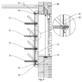
- the thermal shutter system shown in Figure 4 is similar to that shown in Figures 1 and 2 except that a motor and gearbox assembly 15 is mounted on the upright member 5 between the upright member and a shutter blade.
- the thermal shutter system may be operated manually or may be operated by way of a control panel, for example providing a number of pre-programmed settings in addition to manual and/or user-defined settings.
- the control system may additionally identify, memorise and adjust the position of the shutter blades based on the time of day and/or the time of the year and the desired functions.
- Each blade may be provided with a unique identification which enables the blade to be recognised for repositioning.
- identification may be effected by an optical device which is provided on a common driving system and which identifies each blade by its identification, such as a unique identification code.
- the elevation and degree of rotation of each blade may be recognised and recorded by one or more local and/or common positioning sensors.
- the thermal shutter system can function as a solar shade, as a light shelf and also as a security screen (for example, when a building is unoccupied).
- the system is able to reduce energy consumption for heating and/or for cooling a building and is also able to reduce energy consumption for lighting by functioning as a light shelf and reducing the need for artificial lighting.
- the system is also able to reduce glare, for example reducing glare in one part of a building while maintaining natural lighting in another part.
- the system is also able to provide security for a building, for example acting as a secondary security device when windows are left open for ventilation.
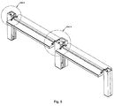
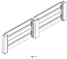
- the thermal shutter system shown in Figures 5 to 11 is similar to that of Figures 1 to 4 , but is in the form of a symmetrical internal shutter system.
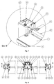
- the thermal shutter system of Figures 5 to 11 includes a primary gearbox 31 between two sets of blades 1, and two secondary gearboxes 33 at the sides of the system, the gearboxes being synchronised by means of a lateral shaft 35 which is covered with a protective sleeve 37.
- Several pairs of blades 1 are provided, the blades being positioned in an end-to-end relationship and being filled with suitable thermal insulating material, such as vacuum insulating panels (VIPs).
- VIPs vacuum insulating panels
- Seals 11 may be provided between the ends of the half-blades and the frame to provide a seal between the frame and the blades when the half-blades are in an upright configuration as shown in Figures 10 and 11 . This helps to make the shutter system relatively air-tight (and weatherproof if used externally).
- the gearboxes 31, 33 are movably supported on primary 41 or secondary 43 guide tracks forming part of the frame and which may be secured to walls of the building or to a secondary supporting structure.
- the rear of the primary guide track 41, facing the window of the building, is insulated and provided with a cover 45 of low thermal conduction material to reduce thermal bridging.
- the fronts of the guide tracks may be provided with covers 61 where the speed of movement of the components of the system is sufficiently fast to present risk of injury when inadvertently touched.
- Electrical wiring and electric/electrical equipment for the shutter system is located within the primary guide track 41.
- Three electric motors are associated with each primary gearbox 31, with a primary motor 47 being provided to effect simultaneous rise and fall of the half-blades and a secondary motor 49 being provided to effect independent rotation of each half-blade.
- the gearboxes 31, 33 are mounted on three leadscrews, two right-hand leadscrews 27 at the sides and one left-hand leadscrew in the centre (or vice versa).
- the blades 1 are fixed to the gearboxes by means of spiders 29 with the result that the blades are located in a plane offset from the axis about which they are rotatable.
- a worm 51 and wheel 53 mechanism is used for rotating the blades 1, while bevel gears 55 and pinions 57 and leadscrew nuts 63 are used, together with the synchronising shafts 35 to effect rise and fall of the blades.
- leadscrew nuts 63 are attached to the bevel gears 55.
- the gears 55 may be made in such a way as to act as, or to accommodate, a leadscrew nut within the gear.
- the synchronising shafts 35 are connected to the gearboxes 31, 33 by way of couplings 59.
- the blades 1 can be placed in different configurations (first and second closed configurations), enabling the fully deployed (closed) shutters to act in two different modes. These are a thermally insulating mode as shown in Figure 10 and a ventilating mode as shown in Figure 11 .
- a thermally insulating mode as shown in Figure 10
- a ventilating mode as shown in Figure 11 .
- the ends of the blades 1 contact the seals 11, while in Figure 11 the blades have been rotated through 180 degrees and, while closed, there is a space between the ends of the blades and the frame. In either case, the security of a building incorporating the thermal shutter system is not compromised when the building is not occupied.
Landscapes
- Engineering & Computer Science (AREA)
- Structural Engineering (AREA)
- Civil Engineering (AREA)
- Architecture (AREA)
- Operating, Guiding And Securing Of Roll- Type Closing Members (AREA)
- Blinds (AREA)
- Specific Sealing Or Ventilating Devices For Doors And Windows (AREA)
- Air-Flow Control Members (AREA)
Claims (15)
- Système de volets d'isolation thermique comprenant une pluralité de volets allongés (1), les volets étant montés pour pivoter autour de la direction de leur longueur et étant montés pour se déplacer dans une direction essentiellement perpendiculaire à la direction de leur longueur, caractérisé en ce que le système comprend en outre un mécanisme d'entraînement preneur-placeur (31, 33, 47, 49) construit pour déplacer chaque volet indépendamment de l'autre ou des autres volets, le mécanisme d'entraînement preneur-placeur comprenant un capteur construit pour identifier spécifiquement chaque volet (1) du système.
- Système de volets selon la revendication 1, dans lequel les volets (1) sont agencés en paires de volets auxiliaires positionnés bout-à-bout, les volets auxiliaires (1) de chaque paire étant montés facultativement pour pivoter indépendamment, mais pour se déplacer simultanément perpendiculairement à la direction de la longueur.
- Système de volets selon l'une quelconque des revendications précédentes, dans lequel les volets (1) sont montés à l'intérieur d'un cadre (3), le cadre (3) comprenant facultativement un joint pour assurer l'étanchéité contre une surface à laquelle le cadre est fixé.
- Système de volets selon la revendication 3, dans lequel un joint (11) est prévu entre les volets (1) et le cadre (3) et/ou entre des volets contigus, le joint (11) étant sélectionné, par exemple, entre un joint à brosse et un joint élastomère.
- Système de volets selon l'une quelconque des revendications précédentes, dans lequel les volets (1) sont montés pour pivoter autour d'un axe positionné à proximité d'un bord longitudinal du volet.
- Système de volets selon la revendication 5, dans lequel l'axe est positionné à l'intérieur du volet (1).
- Système de volets selon l'une quelconque des revendications 1 à 5, dans lequel les volets (1) sont agencés dans des plans décalés par rapport à l'axe autour duquel ils peuvent pivoter, les volets (1) pouvant facultativement pivoter jusqu'à deux configurations fermées alternatives, une dans laquelle les extrémités des volets butent contre un joint (11) et une autre dans laquelle les extrémités des volets sont espacés du joint.
- Système de volets selon l'une quelconque des revendications précédentes, dans lequel les volets (1) sont essentiellement rectangulaires.
- Système de volets selon l'une quelconque des revendications précédentes, dans lequel les volets (1) sont opaques, translucides ou transparents.
- Système de volets selon l'une quelconque des revendications précédentes, dans lequel les volets (1) sont constitués ou remplis d'un matériau d'isolation thermique.
- Système de volets selon l'une quelconque des revendications précédentes, dans lequel les volets (1) sont munis d'un panneau solaire sur au moins une de leurs faces.
- Système de volets selon l'une quelconque des revendications précédentes, dans lequel au moins une face d'au moins un des volets (1) est constituée ou munie d'un matériau réfléchissant.
- Système de volets selon l'une quelconque des revendications précédentes, dans lequel les volets (1) sont montés sur une pluralité d'éléments linéaires (27), les éléments linéaires (27) s'étendant facultativement dans le cadre (3), et les volets (1) étant facultativement montés pour pivoter ou se déplacer par rapport aux éléments linéaires (27).
- Système de volets selon l'une quelconque des revendications précédentes, dans lequel le capteur est constitué d'un capteur optique adapté pour reconnaître un code visuel, tel qu'un code d'identification unique, prévu sur chaque volet (1).
- Système de volets selon l'une quelconque des revendications précédentes, dans lequel un moyen est prévu pour enregistrer l'élévation et le degré de rotation de chaque volet (1), le moyen d'enregistrement comprenant facultativement un mécanisme pour commander l'élévation et le degré de rotation de chaque volet (1).
Applications Claiming Priority (2)
| Application Number | Priority Date | Filing Date | Title |
|---|---|---|---|
| GBGB1102111.0A GB201102111D0 (en) | 2011-02-08 | 2011-02-08 | Thermal shutter system |
| PCT/EP2012/051803 WO2012107350A1 (fr) | 2011-02-08 | 2012-02-02 | Système de volets de régulation thermique |
Publications (2)
| Publication Number | Publication Date |
|---|---|
| EP2673445A1 EP2673445A1 (fr) | 2013-12-18 |
| EP2673445B1 true EP2673445B1 (fr) | 2016-06-15 |
Family
ID=43836344
Family Applications (1)
| Application Number | Title | Priority Date | Filing Date |
|---|---|---|---|
| EP12702257.2A Active EP2673445B1 (fr) | 2011-02-08 | 2012-02-02 | Système de volets de régulation thermique |
Country Status (5)
| Country | Link |
|---|---|
| US (1) | US9410365B2 (fr) |
| EP (1) | EP2673445B1 (fr) |
| CN (1) | CN103443382B (fr) |
| GB (1) | GB201102111D0 (fr) |
| WO (1) | WO2012107350A1 (fr) |
Families Citing this family (10)
| Publication number | Priority date | Publication date | Assignee | Title |
|---|---|---|---|---|
| GB201102111D0 (en) * | 2011-02-08 | 2011-03-23 | Wjp Holdings Ltd | Thermal shutter system |
| FR3027334B1 (fr) | 2014-10-15 | 2017-02-24 | Biossun | Installation pour couvrir et decouvrir une surface a l'aide de lames orientables automotrices |
| BE1022563B1 (nl) * | 2014-10-16 | 2016-06-02 | Renson Sunprotection Screens Nv | Lamelleninrichting |
| AU2016204260B2 (en) | 2015-06-25 | 2021-04-08 | Hunter Douglas Inc. | Shutter assembly with motorized louver drive system |
| FR3049976B1 (fr) * | 2016-04-12 | 2022-08-05 | Biossun | Installation pour couvrir et decouvrir une surface a l'aide de lames orientables automotrices attelees |
| FR3075838B1 (fr) * | 2017-12-27 | 2020-02-28 | Biossun | Installation a lames orientables independamment les unes des autres |
| IT201800002930A1 (it) * | 2018-02-22 | 2019-08-22 | Roberto Montelatici | Tenda alla veneziana con vetri pirolitici |
| CN108952532B (zh) * | 2018-08-27 | 2023-09-26 | 李红生 | 一种电动智能控制滑块运行的方法和百叶片的结构 |
| US11603704B2 (en) * | 2019-05-16 | 2023-03-14 | Imam Abdulrahman Bin Faisal University | System and method for controlling solar powered smart windows |
| US12385256B1 (en) * | 2023-06-09 | 2025-08-12 | Diego M. Bazan | Environmentally friendly automatic shade actuating system |
Family Cites Families (17)
| Publication number | Priority date | Publication date | Assignee | Title |
|---|---|---|---|---|
| US2232372A (en) * | 1938-08-03 | 1941-02-18 | Charles L Dierker | Folding garage door |
| US2861836A (en) * | 1954-08-23 | 1958-11-25 | Goeggel John | Retractable motor vehicle top |
| GB885992A (en) * | 1959-08-18 | 1962-01-03 | Screen Master Light Engineerin | Improvements relating to venetian-type windows |
| US3810330A (en) * | 1972-09-05 | 1974-05-14 | American Standard Inc | Movable panel system |
| SE394177B (sv) * | 1975-02-04 | 1977-06-13 | L Anderson | Jalusianordning |
| US4279240A (en) * | 1979-12-04 | 1981-07-21 | Artusy Bobby L | Self-regulating solar window device |
| US6014839A (en) * | 1997-12-05 | 2000-01-18 | Bryan Ruggles | Electronic actuator for architectural shutters |
| US20030098133A1 (en) * | 2001-11-29 | 2003-05-29 | Newell Window Furnishings, Inc. | Architectural opening covering having automatic positioning capability |
| US7681620B2 (en) * | 2003-01-30 | 2010-03-23 | Parma Shutter Technologies Ltd | Stacking mechanism |
| US7111952B2 (en) * | 2003-03-24 | 2006-09-26 | Lutron Electronics Co., Inc. | System to control daylight and artificial illumination and sun glare in a space |
| CN2677562Y (zh) * | 2004-02-19 | 2005-02-09 | 赵明桥 | 百页安全窗 |
| US7617857B2 (en) * | 2006-02-02 | 2009-11-17 | Brad Froese | Illuminated window blind assembly |
| NZ574903A (en) * | 2006-07-14 | 2011-12-22 | Jillian Jolly | Louvre assembly with screw thread provided in louvre central bore for grub screw and spring loaded mounting pin |
| DE202006018968U1 (de) | 2006-12-15 | 2007-03-29 | Fenster-Keller Gmbh+Co. Fenster+Fassaden Kg | Verstellbares Lamellenfenster |
| PT2245254E (pt) | 2008-02-15 | 2011-11-04 | Hunter Douglas Ind Bv | Mecanismo de rotação de persianas |
| CN101787844B (zh) * | 2010-01-19 | 2012-07-04 | 中国建筑设计研究院 | 移动式保温隔热百叶窗及其自动控制方法 |
| GB201102111D0 (en) * | 2011-02-08 | 2011-03-23 | Wjp Holdings Ltd | Thermal shutter system |
-
2011
- 2011-02-08 GB GBGB1102111.0A patent/GB201102111D0/en not_active Ceased
-
2012
- 2012-02-02 CN CN201280014796.5A patent/CN103443382B/zh not_active Expired - Fee Related
- 2012-02-02 EP EP12702257.2A patent/EP2673445B1/fr active Active
- 2012-02-02 WO PCT/EP2012/051803 patent/WO2012107350A1/fr not_active Ceased
- 2012-02-02 US US13/261,706 patent/US9410365B2/en not_active Expired - Fee Related
Non-Patent Citations (1)
| Title |
|---|
| None * |
Also Published As
| Publication number | Publication date |
|---|---|
| CN103443382B (zh) | 2015-12-23 |
| GB201102111D0 (en) | 2011-03-23 |
| WO2012107350A1 (fr) | 2012-08-16 |
| EP2673445A1 (fr) | 2013-12-18 |
| US9410365B2 (en) | 2016-08-09 |
| US20140000164A1 (en) | 2014-01-02 |
| CN103443382A (zh) | 2013-12-11 |
Similar Documents
| Publication | Publication Date | Title |
|---|---|---|
| US9410365B2 (en) | Thermal shutter system | |
| US10214958B2 (en) | Customizable glass wall system | |
| CN103717819B (zh) | 用于建筑物的孔口或建筑物的表面部的覆盖装置以及用于这种覆盖装置的驱动系统 | |
| KR101586399B1 (ko) | 햇빛 차단 및 빗물 유입 방지용 루버가 구비된 창호 | |
| US20130056159A1 (en) | Louvre vane system | |
| US10947777B2 (en) | Customizable glass wall system with partitioned film | |
| KR101136866B1 (ko) | 이중 개폐 기능을 가지는 블라인드 창호 | |
| KR20110057373A (ko) | 에너지 절약형 다기능 블라인드 창호 | |
| KR20140053922A (ko) | 가변 회전 천창시스템 | |
| CN109518854A (zh) | 多功能单元式玻璃幕墙 | |
| KR20150131709A (ko) | 투광형 박막 태양전지 모듈을 구비한 회전형 이중외피 시스템 | |
| KR101170061B1 (ko) | 전동 슬라이드 갤러리 창을 포함한 구조물 | |
| KR101173175B1 (ko) | 이중 개폐 시스템 블라인드 창호 | |
| US8820010B2 (en) | Jalousie window with daylighting and shading shelf | |
| JP3745873B2 (ja) | ルーバー入り複層ガラス | |
| JP3268037B2 (ja) | 複層型ルーバー | |
| KR101707479B1 (ko) | 단열 창호 | |
| EP2989277B1 (fr) | Écran de protection de la vie privée pour fenêtre | |
| JP2013234490A (ja) | 可視光透過性ブラインドとその使用方法 | |
| CN210564275U (zh) | 一种电动调节式窗帘 | |
| JP2012184862A (ja) | 建物 | |
| CN111075329B (zh) | 一种通风性良好的窗户 | |
| JPH0765445B2 (ja) | 採光装置 | |
| KR101774001B1 (ko) | 햇빛 차단 시스템이 부착된 단열복합창 | |
| JP2007092350A (ja) | ルーバ装置 |
Legal Events
| Date | Code | Title | Description |
|---|---|---|---|
| PUAI | Public reference made under article 153(3) epc to a published international application that has entered the european phase |
Free format text: ORIGINAL CODE: 0009012 |
|
| 17P | Request for examination filed |
Effective date: 20130904 |
|
| AK | Designated contracting states |
Kind code of ref document: A1 Designated state(s): AL AT BE BG CH CY CZ DE DK EE ES FI FR GB GR HR HU IE IS IT LI LT LU LV MC MK MT NL NO PL PT RO RS SE SI SK SM TR |
|
| DAX | Request for extension of the european patent (deleted) | ||
| GRAP | Despatch of communication of intention to grant a patent |
Free format text: ORIGINAL CODE: EPIDOSNIGR1 |
|
| INTG | Intention to grant announced |
Effective date: 20160210 |
|
| GRAS | Grant fee paid |
Free format text: ORIGINAL CODE: EPIDOSNIGR3 |
|
| GRAA | (expected) grant |
Free format text: ORIGINAL CODE: 0009210 |
|
| AK | Designated contracting states |
Kind code of ref document: B1 Designated state(s): AL AT BE BG CH CY CZ DE DK EE ES FI FR GB GR HR HU IE IS IT LI LT LU LV MC MK MT NL NO PL PT RO RS SE SI SK SM TR |
|
| REG | Reference to a national code |
Ref country code: CH Ref legal event code: EP Ref country code: GB Ref legal event code: FG4D |
|
| REG | Reference to a national code |
Ref country code: IE Ref legal event code: FG4D |
|
| REG | Reference to a national code |
Ref country code: AT Ref legal event code: REF Ref document number: 806614 Country of ref document: AT Kind code of ref document: T Effective date: 20160715 |
|
| REG | Reference to a national code |
Ref country code: DE Ref legal event code: R096 Ref document number: 602012019539 Country of ref document: DE |
|
| REG | Reference to a national code |
Ref country code: LT Ref legal event code: MG4D |
|
| REG | Reference to a national code |
Ref country code: NL Ref legal event code: MP Effective date: 20160615 |
|
| PG25 | Lapsed in a contracting state [announced via postgrant information from national office to epo] |
Ref country code: FI Free format text: LAPSE BECAUSE OF FAILURE TO SUBMIT A TRANSLATION OF THE DESCRIPTION OR TO PAY THE FEE WITHIN THE PRESCRIBED TIME-LIMIT Effective date: 20160615 Ref country code: NO Free format text: LAPSE BECAUSE OF FAILURE TO SUBMIT A TRANSLATION OF THE DESCRIPTION OR TO PAY THE FEE WITHIN THE PRESCRIBED TIME-LIMIT Effective date: 20160915 Ref country code: LT Free format text: LAPSE BECAUSE OF FAILURE TO SUBMIT A TRANSLATION OF THE DESCRIPTION OR TO PAY THE FEE WITHIN THE PRESCRIBED TIME-LIMIT Effective date: 20160615 |
|
| REG | Reference to a national code |
Ref country code: AT Ref legal event code: MK05 Ref document number: 806614 Country of ref document: AT Kind code of ref document: T Effective date: 20160615 |
|
| PG25 | Lapsed in a contracting state [announced via postgrant information from national office to epo] |
Ref country code: SE Free format text: LAPSE BECAUSE OF FAILURE TO SUBMIT A TRANSLATION OF THE DESCRIPTION OR TO PAY THE FEE WITHIN THE PRESCRIBED TIME-LIMIT Effective date: 20160615 Ref country code: LV Free format text: LAPSE BECAUSE OF FAILURE TO SUBMIT A TRANSLATION OF THE DESCRIPTION OR TO PAY THE FEE WITHIN THE PRESCRIBED TIME-LIMIT Effective date: 20160615 Ref country code: NL Free format text: LAPSE BECAUSE OF FAILURE TO SUBMIT A TRANSLATION OF THE DESCRIPTION OR TO PAY THE FEE WITHIN THE PRESCRIBED TIME-LIMIT Effective date: 20160615 Ref country code: GR Free format text: LAPSE BECAUSE OF FAILURE TO SUBMIT A TRANSLATION OF THE DESCRIPTION OR TO PAY THE FEE WITHIN THE PRESCRIBED TIME-LIMIT Effective date: 20160916 Ref country code: HR Free format text: LAPSE BECAUSE OF FAILURE TO SUBMIT A TRANSLATION OF THE DESCRIPTION OR TO PAY THE FEE WITHIN THE PRESCRIBED TIME-LIMIT Effective date: 20160615 Ref country code: RS Free format text: LAPSE BECAUSE OF FAILURE TO SUBMIT A TRANSLATION OF THE DESCRIPTION OR TO PAY THE FEE WITHIN THE PRESCRIBED TIME-LIMIT Effective date: 20160615 |
|
| PG25 | Lapsed in a contracting state [announced via postgrant information from national office to epo] |
Ref country code: IT Free format text: LAPSE BECAUSE OF FAILURE TO SUBMIT A TRANSLATION OF THE DESCRIPTION OR TO PAY THE FEE WITHIN THE PRESCRIBED TIME-LIMIT Effective date: 20160615 Ref country code: RO Free format text: LAPSE BECAUSE OF FAILURE TO SUBMIT A TRANSLATION OF THE DESCRIPTION OR TO PAY THE FEE WITHIN THE PRESCRIBED TIME-LIMIT Effective date: 20160615 Ref country code: IS Free format text: LAPSE BECAUSE OF FAILURE TO SUBMIT A TRANSLATION OF THE DESCRIPTION OR TO PAY THE FEE WITHIN THE PRESCRIBED TIME-LIMIT Effective date: 20161015 Ref country code: EE Free format text: LAPSE BECAUSE OF FAILURE TO SUBMIT A TRANSLATION OF THE DESCRIPTION OR TO PAY THE FEE WITHIN THE PRESCRIBED TIME-LIMIT Effective date: 20160615 Ref country code: CZ Free format text: LAPSE BECAUSE OF FAILURE TO SUBMIT A TRANSLATION OF THE DESCRIPTION OR TO PAY THE FEE WITHIN THE PRESCRIBED TIME-LIMIT Effective date: 20160615 Ref country code: SK Free format text: LAPSE BECAUSE OF FAILURE TO SUBMIT A TRANSLATION OF THE DESCRIPTION OR TO PAY THE FEE WITHIN THE PRESCRIBED TIME-LIMIT Effective date: 20160615 |
|
| PG25 | Lapsed in a contracting state [announced via postgrant information from national office to epo] |
Ref country code: SM Free format text: LAPSE BECAUSE OF FAILURE TO SUBMIT A TRANSLATION OF THE DESCRIPTION OR TO PAY THE FEE WITHIN THE PRESCRIBED TIME-LIMIT Effective date: 20160615 Ref country code: PT Free format text: LAPSE BECAUSE OF FAILURE TO SUBMIT A TRANSLATION OF THE DESCRIPTION OR TO PAY THE FEE WITHIN THE PRESCRIBED TIME-LIMIT Effective date: 20161017 Ref country code: PL Free format text: LAPSE BECAUSE OF FAILURE TO SUBMIT A TRANSLATION OF THE DESCRIPTION OR TO PAY THE FEE WITHIN THE PRESCRIBED TIME-LIMIT Effective date: 20160615 Ref country code: ES Free format text: LAPSE BECAUSE OF FAILURE TO SUBMIT A TRANSLATION OF THE DESCRIPTION OR TO PAY THE FEE WITHIN THE PRESCRIBED TIME-LIMIT Effective date: 20160615 Ref country code: AT Free format text: LAPSE BECAUSE OF FAILURE TO SUBMIT A TRANSLATION OF THE DESCRIPTION OR TO PAY THE FEE WITHIN THE PRESCRIBED TIME-LIMIT Effective date: 20160615 |
|
| REG | Reference to a national code |
Ref country code: DE Ref legal event code: R097 Ref document number: 602012019539 Country of ref document: DE |
|
| PLBE | No opposition filed within time limit |
Free format text: ORIGINAL CODE: 0009261 |
|
| STAA | Information on the status of an ep patent application or granted ep patent |
Free format text: STATUS: NO OPPOSITION FILED WITHIN TIME LIMIT |
|
| 26N | No opposition filed |
Effective date: 20170316 |
|
| PG25 | Lapsed in a contracting state [announced via postgrant information from national office to epo] |
Ref country code: DK Free format text: LAPSE BECAUSE OF FAILURE TO SUBMIT A TRANSLATION OF THE DESCRIPTION OR TO PAY THE FEE WITHIN THE PRESCRIBED TIME-LIMIT Effective date: 20160615 |
|
| PG25 | Lapsed in a contracting state [announced via postgrant information from national office to epo] |
Ref country code: SI Free format text: LAPSE BECAUSE OF FAILURE TO SUBMIT A TRANSLATION OF THE DESCRIPTION OR TO PAY THE FEE WITHIN THE PRESCRIBED TIME-LIMIT Effective date: 20160615 |
|
| PG25 | Lapsed in a contracting state [announced via postgrant information from national office to epo] |
Ref country code: MC Free format text: LAPSE BECAUSE OF FAILURE TO SUBMIT A TRANSLATION OF THE DESCRIPTION OR TO PAY THE FEE WITHIN THE PRESCRIBED TIME-LIMIT Effective date: 20160615 |
|
| REG | Reference to a national code |
Ref country code: CH Ref legal event code: PL |
|
| PG25 | Lapsed in a contracting state [announced via postgrant information from national office to epo] |
Ref country code: CH Free format text: LAPSE BECAUSE OF NON-PAYMENT OF DUE FEES Effective date: 20170228 Ref country code: LI Free format text: LAPSE BECAUSE OF NON-PAYMENT OF DUE FEES Effective date: 20170228 |
|
| REG | Reference to a national code |
Ref country code: IE Ref legal event code: MM4A |
|
| REG | Reference to a national code |
Ref country code: FR Ref legal event code: ST Effective date: 20171031 |
|
| PG25 | Lapsed in a contracting state [announced via postgrant information from national office to epo] |
Ref country code: LU Free format text: LAPSE BECAUSE OF NON-PAYMENT OF DUE FEES Effective date: 20170202 |
|
| PG25 | Lapsed in a contracting state [announced via postgrant information from national office to epo] |
Ref country code: FR Free format text: LAPSE BECAUSE OF NON-PAYMENT OF DUE FEES Effective date: 20170228 |
|
| PG25 | Lapsed in a contracting state [announced via postgrant information from national office to epo] |
Ref country code: IE Free format text: LAPSE BECAUSE OF NON-PAYMENT OF DUE FEES Effective date: 20170202 |
|
| PG25 | Lapsed in a contracting state [announced via postgrant information from national office to epo] |
Ref country code: MT Free format text: LAPSE BECAUSE OF NON-PAYMENT OF DUE FEES Effective date: 20170202 |
|
| PG25 | Lapsed in a contracting state [announced via postgrant information from national office to epo] |
Ref country code: AL Free format text: LAPSE BECAUSE OF FAILURE TO SUBMIT A TRANSLATION OF THE DESCRIPTION OR TO PAY THE FEE WITHIN THE PRESCRIBED TIME-LIMIT Effective date: 20160615 |
|
| PG25 | Lapsed in a contracting state [announced via postgrant information from national office to epo] |
Ref country code: HU Free format text: LAPSE BECAUSE OF FAILURE TO SUBMIT A TRANSLATION OF THE DESCRIPTION OR TO PAY THE FEE WITHIN THE PRESCRIBED TIME-LIMIT; INVALID AB INITIO Effective date: 20120202 |
|
| PG25 | Lapsed in a contracting state [announced via postgrant information from national office to epo] |
Ref country code: BG Free format text: LAPSE BECAUSE OF FAILURE TO SUBMIT A TRANSLATION OF THE DESCRIPTION OR TO PAY THE FEE WITHIN THE PRESCRIBED TIME-LIMIT Effective date: 20160615 |
|
| PG25 | Lapsed in a contracting state [announced via postgrant information from national office to epo] |
Ref country code: CY Free format text: LAPSE BECAUSE OF NON-PAYMENT OF DUE FEES Effective date: 20160615 |
|
| PG25 | Lapsed in a contracting state [announced via postgrant information from national office to epo] |
Ref country code: MK Free format text: LAPSE BECAUSE OF FAILURE TO SUBMIT A TRANSLATION OF THE DESCRIPTION OR TO PAY THE FEE WITHIN THE PRESCRIBED TIME-LIMIT Effective date: 20160615 |
|
| PG25 | Lapsed in a contracting state [announced via postgrant information from national office to epo] |
Ref country code: TR Free format text: LAPSE BECAUSE OF FAILURE TO SUBMIT A TRANSLATION OF THE DESCRIPTION OR TO PAY THE FEE WITHIN THE PRESCRIBED TIME-LIMIT Effective date: 20160615 |
|
| PGFP | Annual fee paid to national office [announced via postgrant information from national office to epo] |
Ref country code: BE Payment date: 20210218 Year of fee payment: 10 |
|
| REG | Reference to a national code |
Ref country code: BE Ref legal event code: MM Effective date: 20220228 |
|
| PG25 | Lapsed in a contracting state [announced via postgrant information from national office to epo] |
Ref country code: BE Free format text: LAPSE BECAUSE OF NON-PAYMENT OF DUE FEES Effective date: 20220228 |
|
| P01 | Opt-out of the competence of the unified patent court (upc) registered |
Effective date: 20230518 |
|
| REG | Reference to a national code |
Ref country code: DE Ref legal event code: R081 Ref document number: 602012019539 Country of ref document: DE Owner name: WJP HOLDINGS 2025 LTD., LICHFIELD, GB Free format text: FORMER OWNER: WJP HOLDINGS LTD., LICHFIELD, STAFFORDSHIRE, GB |
|
| REG | Reference to a national code |
Ref country code: GB Ref legal event code: 732E Free format text: REGISTERED BETWEEN 20260305 AND 20260311 |
|
| PGFP | Annual fee paid to national office [announced via postgrant information from national office to epo] |
Ref country code: GB Payment date: 20260203 Year of fee payment: 15 |
|
| PGFP | Annual fee paid to national office [announced via postgrant information from national office to epo] |
Ref country code: DE Payment date: 20260204 Year of fee payment: 15 |