EP2673466B1 - Appareil et procédé de production et de test de puits - Google Patents
Appareil et procédé de production et de test de puits Download PDFInfo
- Publication number
- EP2673466B1 EP2673466B1 EP12709955.4A EP12709955A EP2673466B1 EP 2673466 B1 EP2673466 B1 EP 2673466B1 EP 12709955 A EP12709955 A EP 12709955A EP 2673466 B1 EP2673466 B1 EP 2673466B1
- Authority
- EP
- European Patent Office
- Prior art keywords
- fluids
- sampling
- conduit
- well
- production
- Prior art date
- Legal status (The legal status is an assumption and is not a legal conclusion. Google has not performed a legal analysis and makes no representation as to the accuracy of the status listed.)
- Active
Links
Images



Classifications
-
- E—FIXED CONSTRUCTIONS
- E21—EARTH OR ROCK DRILLING; MINING
- E21B—EARTH OR ROCK DRILLING; OBTAINING OIL, GAS, WATER, SOLUBLE OR MELTABLE MATERIALS OR A SLURRY OF MINERALS FROM WELLS
- E21B49/00—Testing the nature of borehole walls; Formation testing; Methods or apparatus for obtaining samples of soil or well fluids, specially adapted to earth drilling or wells
- E21B49/08—Obtaining fluid samples or testing fluids, in boreholes or wells
- E21B49/087—Well testing, e.g. testing for reservoir productivity or formation parameters
- E21B49/088—Well testing, e.g. testing for reservoir productivity or formation parameters combined with sampling
-
- E—FIXED CONSTRUCTIONS
- E21—EARTH OR ROCK DRILLING; MINING
- E21B—EARTH OR ROCK DRILLING; OBTAINING OIL, GAS, WATER, SOLUBLE OR MELTABLE MATERIALS OR A SLURRY OF MINERALS FROM WELLS
- E21B47/00—Survey of boreholes or wells
- E21B47/10—Locating fluid leaks, intrusions or movements
-
- E—FIXED CONSTRUCTIONS
- E21—EARTH OR ROCK DRILLING; MINING
- E21B—EARTH OR ROCK DRILLING; OBTAINING OIL, GAS, WATER, SOLUBLE OR MELTABLE MATERIALS OR A SLURRY OF MINERALS FROM WELLS
- E21B49/00—Testing the nature of borehole walls; Formation testing; Methods or apparatus for obtaining samples of soil or well fluids, specially adapted to earth drilling or wells
- E21B49/08—Obtaining fluid samples or testing fluids, in boreholes or wells
- E21B49/086—Withdrawing samples at the surface
Definitions
- the present disclosure relates to apparatus and methods for testing, sampling and/or recovering fluids from a well and/or injecting fluids into a well.
- Embodiments of the disclosure can be used for fluid testing during recovery and injection of fluids, as well as sampling of the fluids. Some embodiments relate especially but not exclusively to recovery and injection, into either the same, or a different well.
- the production fluids wash out the dense completion fluids used to control wellbore pressure during the completion phases of the well construction, and much of the debris and sand is also washed out of the well at this phase.
- the early production fluids are often mixed-phase fluids with a mixture of gasses, liquids and solids. They will often have a high gas content, which must be flared off at the surface.
- the maximum flow rate of the production fluids from the well during well testing is largely determined by the gas content, because flaring is highly exothermic and it is only possible to flare off gasses at a certain rate at the surface.
- the present disclosure relates to apparatus and methods for testing, sampling and/or recovering fluids from a well including one or more of, in various combinations, a flow measurement device, a pressure sensor, a temperature sensor, a sampling device and chamber, a solids or particle separator, filter or knockout device, a conduit or other access to the surface, a data storage module, a physical interface for various components, and wherein the apparatus and methods are locatable and operable completely subsea.
- a well testing device (8) for conducting well test operations on an oil, gas, or water well including a production flowline (20), the device (8) comprising:
- the method is carried out as part of a well test procedure before primary recovery of reservoir fluids commences.
- the separation of particles from the fluid may be carried out using a particle separator. Particles may also be separated by sampling of the fluid on a continuous or intermittent basis.
- the well test system includes a particle detector typically located upstream in the conduit from the particle separator, and configured to detect particles in the fluids flowing from the production flowline to the particle separator.
- the particle detector includes an acoustic transducer such as a vibration sensor, a piezoelectric transducer or some other design of particle detector.
- the particle detector can be an optical sensor, which can optionally be configured to detect the particles by light scattering.
- the particle detector is configured to report the presence of particles in the fluids to a controller such as a data storage module, which can optionally transmit a signal to other components of the well test system or testing device, such as the particle separator.
- the controller or data storage module may control other components such that, for example, when particles are detected in the conduit the particle detector sends a signal to the controller which in turn initiates appropriate action in the downstream particle separator to remove the particles from the fluids as they pass through the particle separator.
- the particle detector can detect and report quantitative and/or qualitative aspects of the particles such as, for example, particle density, concentration, and particle size.
- the data reported from the detector can be used to signal the separator to increase speed, decrease speed, start and stop, or other similar actions.
- the testing device includes a measurement device such as, for example, a flow meter, or alternatively a multiphase flow meter.
- the fluids are measured in the measurement device before being sampled.
- the flow meter is coupled into the conduit between the production flowline and the sampling device.
- the measurement device may be upstream from the particle separator, but in some embodiments components of the measurement device can be disposed in discrete locations in the conduit to detect characteristics of the fluids at different points in the conduit, including (optionally) positions that are upstream from the particle separator.
- the well test system includes temperature and/or pressure measurement devices, gauges or sensors to determine the temperature and/or pressure of the production fluids and/or the sampled fluids (or any particular phase of either fluid).
- the sampling device is coupled across a device for creating a pressure differential.
- the device for creating a pressure differential may be a flow restriction in a valve or the like.
- the device for creating a pressure differential may be adjustable so that the pressure differential across the device can be increased or decreased.
- the device includes a choke device configured to restrict the flow of fluids through the choke device, so that a pressure differential is created across the choke device.
- the device includes a venturi device or a similar device for passively generating the pressure differential as a result of fluid flowing through the device.
- the sampling device is coupled to an inlet side of the pressure device and to an outlet side of the pressure device, such that the pressure differential generated by the pressure device (for example, by the flow restriction of a valve) is applied across the sampling device also.
- the pressure differential across the sampling device facilitates the sampling procedure, as it drives the production fluids into the sampling device to flow around the restriction of the valve or other device.
- the sampling device includes a sampling chamber to collect sampled fluids.
- the sampling chamber (and/or optionally the sampling device as a whole) may be detachable from the well test system or testing device and can be isolated from them.
- valves that may be ROV operated enable the isolation of the sampling chamber at a subsea wellhead.
- the ROV may remove and/or replace the sampling chamber.
- the ROV can optionally transport the full sampling chamber containing the sampled fluids to the surface for analysis.
- the sampling device (and optionally the sampling chamber) includes temperature, pressure and other gauges or sensors adapted to monitor and optionally record the temperature, pressure and other conditions of the sampled fluids in the chamber so that the same conditions can be recreated at the surface during analysis.
- the sampling device may include a bypass loop so that the sampling chamber can be bypassed by fluids in the conduit. This allows flushing of the line to remove hydrocarbons before and after recovery of the sampling chamber.
- the conduit may have a stab connector upstream of the sampling device to permit flushing operations by an ROV at the subsea location of the system.
- the flushing stab connector can be isolated by means of ROV operated valves.
- the sampling device can also optionally be configured to collect a sample using a flow through method.
- the particle separator includes a sand filter adapted to separate sand and other particulate matter suspended in the production fluids, and typically has a container for receiving and containing the separated sand or other particles.
- the container (or the particle separator as a whole) can be detachable from the system or testing device to be removed and replaced for maintenance and/or emptying of the container.
- the particle separator is a static helical separator that guides the fluids in a helical path to generate centrifugal forces in the fluid that tend to separate the solids from the liquids.
- a rotary centrifugal separator is used.
- a strainer type separator is used. The particular configuration and type of separator employed will depend upon such factors as the process conditions, the material to be separated from the fluid, the amount of particles to be removed, and the upper limit on the particle content of the downstream fluid.
- the conduit passes through or includes a choke body in the wellhead, such as in the christmas tree at the wellhead.
- the choke body may be located in a branch of the tree, such as in a lateral branch of the tree, or a production or an annulus wing branch connected to a production bore or an annulus bore respectively.
- the choke body may be the production choke body.
- "choke body” means the housing which remains after a choke has been removed from the housing.
- the choke may be a choke of a tree, or a choke of any other kind of manifold.
- the conduit is formed by dividing the central conduit of the choke body using a fluid diverter assembly as described in published application WO/2005/047646 , which is incorporated herein by reference.
- the diverter assembly may be located in a branch of the tree in series with a choke.
- the diverter assembly may be located between the choke and the production wing valve or between the choke and the branch outlet.
- Further alternative embodiments include a diverter assembly located in pipework coupled to the tree, allowing the diverter assembly to be used in addition to a choke, instead of replacing the choke. Passing the conduit through a branch of a tree means that the tree cap does not have to be removed to fit the conduit. Embodiments of the disclosure can therefore be easily retro-fitted to existing trees.
- Embodiments of the disclosure provide that fluids can be diverted from their usual path between the well bore and the outlet of the wing branch.
- the fluids may be produced fluids being recovered and travelling from the well bore to the outlet of a tree.
- the fluids may be injection fluids travelling in the reverse direction into the well bore.
- As the choke is standard equipment, there are well known and safe techniques of removing and replacing the choke as it wears out. The same tried and tested techniques can be used to remove the choke from the choke body and to clamp the diverter assembly onto the choke body, without the risk of leaking well fluids into the ocean. This enables new pipe work to be connected to the choke body and hence enables safe re-routing of the produced fluids, without having to undertake the considerable risk of disconnecting and reconnecting any of the existing pipes (e.g., the outlet header).
- the diverter assembly provides a barrier to separate an outlet from an inlet.
- the barrier may separate a branch outlet from a production bore of a tree.
- the barrier includes a plug, which may be located inside the choke body (or other part of the manifold branch) to block the branch outlet.
- the plug is attached to the housing by a stem which extends axially through the internal passage of the housing.
- the diverter assembly provides for diverting fluids from a first portion of a first flowpath to a second flowpath, and for diverting the fluids from a second flowpath to a second portion of the first flowpath.
- at least a part of the first flowpath comprises a branch of the tree.
- the testing device is landed on a well tree, for example the christmas tree, and optionally has stab or other connectors to connect into ports on the tree adapted to make up the conduit.
- the conduit may connect into a fluid diverter assembly located in the body of the production choke of the tree, which can be divided into two (or more) separate portions as described in the published application WO/2005/047646 (e.g., into a bore and annulus). The conduit therefore connects into existing conduits in the tree for export of production fluids from the well and delivery into the production flowline.
- hydraulic control lines, production fluid export conduits and/or electrical connectors can connect to jumpers or other types of connector between the testing device and the tree, enabling the testing device to be controlled or configured by existing tree control lines from the surface, or locally from ROV interaction with the tree.
- the data storage module of the testing device may couple to control modules on the tree.
- the device for creating a pressure differential includes a choke valve connected in series in the conduit between the sampling device and the production flowline inlet.
- the testing device incorporates motion dampers to absorb kinetic energy in the testing device as it lands on the tree.
- the testing device or the tree incorporate guide members to guide the testing device onto the tree in a particular configuration so that the appropriate connectors are made up during the landing process.
- the production fluids are returned to the production fluids outlet of the tree for export from the well by the normal mechanism of the production fluid flowline.
- recovering fluids to the surface or topside facilities for testing and sampling can be avoided.
- some or all of the fluids can be diverted from the production fluid flowline and recovered from the conduit before sampling with the testing device at the wellhead, and diverted to the surface to a sampling circuit on a rig or a ship, after which they can optionally be flared off, recovered, or returned to the production fluid outlet at the wellhead, typically downstream of the device for creating a pressure differential.
- the well test system or testing device may incorporate a surface bypass line connecting to a tapping point on the conduit, typically located between the measuring device and the sampling device (which may be removed by an ROV during the export process), thereby creating a bypass loop for the fluids from the measuring device to the surface sampling device and back into the testing device between, for example, the choke device and the inlet to the production fluids flowline.
- the surface bypass line can be used to inject fluids into the production flowline into the conduit upstream of the testing or sampling device.
- the method is for recovering fluids from a well, and includes the final step of diverting fluids to an outlet of the production fluid flowline for recovery therefrom.
- the method is for injecting fluids into a well. Further, the fluids may be passed in either direction through the conduit.
- the diverter assembly includes a separator to provide two separate regions within the diverter assembly, and the method may include the step of passing fluids through one or both of these regions.
- fluids are passed through the first and the second regions in the same direction.
- fluids are passed through the first and the second regions in opposite directions.
- the fluids are passed through one of the first and second regions and subsequently at least a proportion of these fluids are then passed through the other of the first and the second regions.
- the method includes the step of processing the fluids in a processing apparatus before passing the fluids back to the conduit.
- the diverter assembly may block a passage in the tree between a bore of the tree and its respective outlet.
- Certain embodiments provide the advantage that fluids can be diverted (e.g., recovered or injected into the well, or even diverted from another route, bypassing the well completely) without having to remove and replace any pipes already attached to the manifold branch outlet (e.g., a production wing branch outlet).
- manifold branch outlet e.g., a production wing branch outlet
- any use of any form of the terms “connect,” “engage,” “couple,” “attach,” or any other term describing an interaction between elements is not meant to limit the interaction to direct interaction between the elements and may also include indirect interaction between the elements described.
- Reference to up or down will be made for purposes of description with “up,” “upper,” “upwardly,” or “downstream” meaning toward the surface of the well and with “down,” “lower,” “downwardly,” or “upstream” meaning toward the terminal end of the well, regardless of the wellbore orientation.
- Figure 1 illustrates a well test system 8 including a testing device 8.
- a typical production tree on an offshore oil or gas wellhead comprises a christmas tree with a production bore 1 leading from production tubing (not shown) and adapted to carry production fluids from a perforated region of the production casing in a reservoir (not shown).
- An annulus bore 2 leads to the annulus between the casing and the production tubing and a cap 4.
- the cap 4 is not pressure-sealing, such as for a horizontal or spool tree.
- the cap 4 is a christmas tree cap such as for a vertical tree, which seals off the production and annulus bores 1, 2, and provides a number of hydraulic and electrical control and signal lines, or tree cap control module 3 by which a remote platform or intervention vessel can communicate with and operate the valves in the christmas tree.
- the cap 4 is removable from the christmas tree in order to expose the production and annulus bores in the event that intervention is required and tools need to be inserted into the production or annulus bores 1, 2.
- the flow of fluids through the production and annulus bores is governed by various valves shown in the tree of Fig. 1 .
- the production bore 1 has a branch 10 which is closed by a production wing valve (PWV) 12.
- a production wireline plug (PWP) (PWP) 15, as is found in a horizontal or spool tree, closes the production bore 1 above the branch 10 and PWV 12.
- the tree is a vertical tree and the component 15 is a production swab valve.
- Two lower valves typically close the production bore 1 below the branch 10 and PWV 12.
- the annulus bore is closed by an annulus master valve (AMV) 25.
- An annulus swab valve 32 closes the upper end of the annulus bore 2.
- the valves in the tree are generally hydraulically controlled by hydraulic control channels passing through the tree cap control module 3, in response to signals generated from the surface or from an intervention vessel.
- PWP 15 When production fluids are to be recovered from the production bore 1, PWP 15 is closed, and PWV 12 is opened to open the branch 10 which leads to a production flowline 20.
- Production flowline 20 is generally connected to the branch 10 by a choke and has a production flowline valve (PFV) 21 to close off the bore of the flowline 20.
- PFV production flowline valve
- the conventional tree choke has been removed, and a modified production choke body (PCB) 30 has been connected between the branch 10 and the flowline 20.
- PCB modified production choke body
- the modified production choke body 30 typically comprises a fluid diverter as disclosed in published application WO2005/047646 .
- the fluid diverter can optionally be incorporated into a modified choke body 30 that connects into the inlet and outlet of the existing choke, or the existing choke body can be used with a separate fluid diverter installed within it.
- the fluid diverter has two separate flowpaths 31a and 31 b.
- the flowpaths can be created in a variety of different ways; for example, they can be formed as bore and annulus between concentric tubes, or the central bore of the choke body 30 can be divided by a plate that separates the inlet from the outlet.
- the first flowpath 31a flows from an inlet connected into the branch 10 and connects the branch 10 to a first section 41 of a conduit 40.
- the first section 41 of the conduit 40 may include a 5" pipe with an ROV operable valve.
- the first conduit section 41 extends between the choke body 30 and a particle separator 60.
- the particle separator 60 includes a sand knockout vessel (SKV).
- the conduit section 41 may include a particle detector 50 disposed adjacent or mounted on its outer surface to detect the presence and, optionally, the characteristics of any particles passing through the conduit section 41.
- the particle detector 50 may include an acoustic transducer, which is configured to detect vibrations in the conduit section 41 resulting from particles of sand and the like as they pass the transducer 50.
- Alternative embodiments of the particular separator include components as already described above.
- the transducer 50 may include a signal line that reports the data collected by the transducer 50 to a data storage module 80.
- the sand knockout vessel 60 Downstream of the transducer 50 the sand knockout vessel 60 separates the sand S or other particulates from the fluids and dumps the sand S into the bottom of the vessel for later recovery.
- the sand knockout vessel 60 may have pressure, temperature and other sensors that report the conditions (and possibly quantities) of the materials in the vessel 60 and the pressure drop across it to the data storage module 80.
- the action of the sand knockout vessel 60 is passive.
- the action of the SKV 60 is controlled by signals from the data storage module 80, which can be automatic, in response to the data collected from the transducer 50, timed, or manually activated from the surface ship or rig.
- the flow measurement device 70 Downstream of the sand knockout vessel 60 is a flow measurement device 70.
- the flow measurement device 70 in some embodiments, is a multiphase flow meter (MPFM).
- MPFM 70 is connected to the SKV 60 by a second section 42 of conduit 40.
- the MPFM 70 measures the flow rate of each of the phases of the fluids passing through the conduit section 42, and this data is optionally reported to and stored in the data storage module 80.
- the data storage module 80 may be retrieved and the data analyzed. Such an arrangement avoids the need to provide a direct communications link to the surface.
- the data storage module 80 may also serve to back up data for the system 8 and/or the testing device 18.
- a conduit 43 leading from MPFM 70 connects to a sampling conduit 44 leading to a choke valve 100.
- the sampling conduit 44 includes a branch comprising a sampling circuit 140 connecting the sampling conduit 44 to a sampling device or module 150.
- the sampling circuit 140 can be isolated from the conduit 40 by valves 141.
- the sampling circuit 140 includes a sampling chamber 151, such as a tank, connected in series in the sampling circuit 140.
- the tank 151 is isolated by two pairs of ROV operable valves 152 and 153 on respective sides of the tank 151, and when the valves 152 and 153 are closed, the sampling circuit 140 and the tank 151 can be disconnected and the tank removed and replaced by an ROV.
- the sampling device 150 may include a bypass flushing loop 154 outside the outer valves 153 for flushing fluids through the sampling device 150 but bypassing the tank 151.
- a hot stab port HS3 is provided across the sampling circuit 140 for optional injection and recovery of flushing fluids by an ROV.
- the sampling device 150 may include temperature, pressure, and other gauges, or combinations thereof, that measure the characteristics of the fluids passing through and/or collected in the tank 151, or passing through the sampling circuit 140.
- the collected data can be optionally recorded at the data storage module 80 and transmitted to surface, or collected by the ROV.
- the entire sampling device 150 can be disconnected from the conduit 40 by hydraulic connectors 156.
- the conduit 40 and the sampling device 150 can be connected on a skid incorporating the production choke body 30 and the skid can optionally be landed as a unit on top of the tree using soft landing dampers 6.
- the location of the sampling circuit 140 on the wellhead results in samples that are not affected by pressure and temperature changes resulting from transport of the sample to surface or topside sampling devices before collection of the sample. Furthermore, the subsea location of the sampling circuit 140 enables flow meter calibration (affected by water cut/salinity), tracer detection (understanding the reservoir), understanding the need for scale squeeze (Barium content), and understanding well fluid composition.
- the sampling circuit 140 returns the fluids back to the conduit 40 downstream of the sampling conduit 44, in a return conduit 45 that returns fluids back to the production choke body 30.
- the choke 100 serves as one form of device configured to create a pressure differential across the sampling circuit 140.
- the choke 100 may be variable and can be opened or closed to vary the pressure differential applied by the choke 100 across the sampling circuit 140.
- the choke 100 can choke the flow of fluids flowing directly from conduit 44 into conduit 45, and force more of the fluids through the sampling circuit 140 than can pass through the choke 100.
- the choke 100 is optionally ROV controllable and can also be connected via hydraulic or electrical connectors through the tree to choke control lines already in place in the tree architecture.
- an alternative subsystem 200 includes a venturi component, and is replaceable with the corresponding subsystem of the system 8 and testing device 18 as will be described.
- the subsystem 200 includes a sampling circuit 240 connectable into a conduit 244, similar to the way the sampling circuit 140 connects into the conduit 44.
- the subsystem 200 also includes a sampling device 250 replacing the sampling device 150.
- the sampling device 250 includes a saver sub 254 having a three port bottle 255 coupled into the sampling circuit 240.
- the sampling device 250 includes a sample skid 256 having a piston sample bottle 251 connected as shown. In some embodiments, the sample skid 256 is retrievable.
- the subsystem 200 includes a venturi type component 210. As shown in Figures 3 and 4 , the venturi component includes a port 212 and a inner restricted diameter 211.
- an alternative embodiment may include a pump.
- an alternative subsystem 300 includes a pump, and is replaceable with the corresponding subsystem of the system 8 and testing device 18 as will be described.
- the subsystem 300 includes a sampling circuit 340 connectable into a conduit 344, similar to the way the sampling circuit 140 connects into the conduit 44.
- the subsystem 300 also includes a sampling device 350 replacing the sampling device 150.
- the sampling device 350 includes a saver sub 354 having a three port bottle 355 coupled into the sampling circuit 340.
- the sampling device 350 includes a sample skid 356 having a piston sample bottle 351 connected as shown. In some embodiments, the sample skid 356 is retrievable.
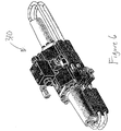
- the subsystem 300 includes a pump component 310.
- the pump 310 is shown in more detail in Figure 6 .
- the return conduit 45 returns the fluids from the sampling circuit 140 and/or the sampling conduit 44 back to the second flowpath 31b of the choke body PCB 30, which delivers the fluids to the production flowline 20 for normal recovery through the existing well connections. Consequently, the testing device 18 provides a subsea testing and/or sampling bypass flowpath or loop for the production fluids to be routed through. The fluids travel through a circulation loop that is completely disposed subsea.
- the embodiments described above include sampling devices 150, 250, 350 using a flow through method to receive and possibly collect a fluid sample.
- the flow through method of receiving and/or taking a sample involves diverting some of the production flow through a tank 151' and returning the fluid back downstream with a sampling device 150'.
- the fluid sampling circuit 140 connects the sampling conduit 44 to a sampling chamber in the form of a tank 151'. Fluid flows into the tank 151' though an inlet line with an inlet valve 149 and out of the tank 151' though one of two outlet lines, 155 and 157, each with corresponding valves 159 and 161. Although initially separate, the outlet line 155 connects with the outlet line 157 at 163 before connection with the conduit 45.
- well testing operations using the embodiments of the well test systems and testing devices herein may be conducted as follows. Fluids from the production bore 1 are routed by the fluid diverter in the PCB 30 into the conduit 40. The fluids are de-sanded by the sand knockout vessel 60 and the flow rates and phase composition of the fluids are measured by the MPFM 70 before being delivered into the sampling circuit 140 via the sampling conduit 44.
- the sampling circuit 140 passes the fluids through the tank 151 and when a representative sample of fluids has been collected in the tank 151, the tank is isolated from the fluid conduit 44 by closing the valves 152 and 153, and the tank 151 is then disconnected from the sampling device 150 and recovered to the surface by ROV for analysis of the fluids collected in the tank 151.
- the choke 100 can be adjusted during the sampling procedure to maintain a pressure differential across the sampling device 150 during the collection of the sample to drive the sample of the fluids into the tank 151. For example, if the pressure differential across the sampling circuit 140 is too low and fluids are not being driven into the tank, the choke 100 can be closed slightly to increase the pressure differential across the sampling circuit 140 and drive more fluids into the tank 151. If the pressure differential is too high across the sampling circuit 140, which may lead to an artificially high proportion of gasses being forced ahead of the liquids into the tank 151, then the choke 100 can be opened to decrease the pressure differential and avoid a misrepresentative sample from being collected in the tank.
- the pressure differential can be kept constant with changing wellbore pressure, thereby facilitating the collection of a more consistent sample in the tank 151.
- the alternative pressure differential components 210, 310 may be used in a similar manner.
- the sampling conduit 44 can have an auxiliary line 46 connected to a riser 47 leading to the surface for treatment of the fluids.
- the sampling circuit 140 is isolated by closing valves 141, and the fluids are diverted from the sampling conduit 44 to the auxiliary line 46 through appropriate one way valves (and optionally pumps) to the surface for collection of the sample if desired.
- the fluids routed to surface can be returned to the wellhead through an auxiliary return line (not shown) that connects into the conduit 40 between the choke 100 and the production choke body 30 in the same way as is described for the sampling circuit 140, so that the choke 100 can be used to control the pressure differential applied across the auxiliary line 46.
- an auxiliary return line (not shown) that connects into the conduit 40 between the choke 100 and the production choke body 30 in the same way as is described for the sampling circuit 140, so that the choke 100 can be used to control the pressure differential applied across the auxiliary line 46.
- the sampling device 150' When sampling with the embodiment shown in Figure 7 , the sampling device 150' is initially closed by closing the valves 149, 159, and 161.
- the tank 151' may initially contain an inhibitor, such as monoethylene glycol (MEG).
- MEG monoethylene glycol
- the tank 151' is then purged by opening valve 161 and displacing the inhibitor out of the outlet line 157.
- the outlet valve 161 Once purge is complete, the outlet valve 161 is closed and the inlet of the tank 151' can be opened by opening the inlet valve 149, allowing fluid to enter the tank 151'.
- the outlet valve 159 on the outlet line 155 is then opened such that fluid circulates through the tank 151' until equilibrium is reached. This allows the pipework to heat up and a thermal equilibrium to be reached.
- the outlet valve 159 is closed and production fluid circulates in the tank 151' for a period of time, producing a representative fluid sample.
- the tank 151' can then be isolated by closing inlet valve 149 and can be recovered to the surface for analysis as discussed above.
- the sample is taken at flowing pressure and can be isobarically decanted and heated in a laboratory.
- the flowing temperature and pressure at the time of the sample can also be recorded from the host equipment instrumentation or from the sampling package.
- the well continues to produce while testing and/or sampling so there are no deferred production costs associated with the test or sample capture.
- a portion of the fluids can be flared off at the surface without being returned to the wellhead.
- the auxiliary line 46 can be used for injection of fluids into the well, for pressure control, or from another well.
- the injection of fluids may be used by the appropriate selection of the fluid being injected, for example, to moderate or kill the well, provide scale treatment, inhibit hydration or corrosion, or for fluid disposal.
- the diverter assembly could be attached to an annulus choke body, instead of to a production choke body.
- All of the apparatus shown and described can be used for both recovery of fluids and injection of fluids by reversing the flow direction.
Landscapes
- Life Sciences & Earth Sciences (AREA)
- Engineering & Computer Science (AREA)
- Geology (AREA)
- Mining & Mineral Resources (AREA)
- Physics & Mathematics (AREA)
- Environmental & Geological Engineering (AREA)
- Fluid Mechanics (AREA)
- General Life Sciences & Earth Sciences (AREA)
- Geochemistry & Mineralogy (AREA)
- Geophysics (AREA)
- Sampling And Sample Adjustment (AREA)
- Testing Of Devices, Machine Parts, Or Other Structures Thereof (AREA)
Claims (20)
- Dispositif d'essai de puits (8) destiné à conduire des opérations d'essai de puits sur un puits de pétrole, de gaz ou à eau comportant une conduite d'écoulement de production (20), le dispositif (8) comprenant :un conduit (44) pouvant être raccordé à la conduite d'écoulement de production (20) pour faire circuler des fluides en provenance de la conduite d'écoulement de production (20) et de nouveau vers la conduite d'écoulement de production (20) ;un dispositif d'essai (18) raccordé au conduit (44) pour recevoir les fluides de circulation, le dispositif d'essai (18) comprenant un dispositif d'échantillonnage (150, 250) et un dispositif déprimogène (100) conçu pour créer une différence de pression afin de réguler l'écoulement de fluides vers le dispositif d'échantillonnage (150, 250);dans lequel le dispositif déprimogène est un venturi (210) ou une pompe (310) ;et caractérisé en ce que le dispositif d'essai comprend en outre un séparateur de particules (60) en amont du dispositif d'échantillonnage et un conduit (40) pour guider les fluides vers le séparateur de particules (60) avant le dispositif d'échantillonnage (150, 250).
- Dispositif d'essai de puits (8) selon la revendication 1, dans lequel le conduit (44) forme une boucle de circulation des fluides, disposée entièrement sous la mer.
- Dispositif d'essai de puits (8) selon l'une des revendications 1 et 2, dans lequel le dispositif d'échantillonnage (150, 250) comprend une chambre d'échantillonnage (151) destinée à recueillir des fluides prélevés à partir de la conduite d'écoulement de production (20).
- Dispositif d'essai de puits (8) selon la revendication 3, dans lequel la chambre d'échantillonnage (151) peut être isolée du dispositif d'essai (18) et peut être détachée du dispositif d'essai (18).
- Dispositif d'essai de puits (8) selon l'une des revendications 3 et 4, comprenant en outre une boucle de dérivation (154) destinée à dériver des fluides en contournant la chambre d'échantillonnage (151).
- Dispositif d'essai de puits (8) selon l'une quelconque des revendications précédentes, comprenant en outre un détecteur de particules (50) situé en amont du séparateur de particules (60), le détecteur de particules (50) étant conçu pour détecter des particules dans les fluides s'écoulant de la conduite d'écoulement de production (20) vers le séparateur de particules (60).
- Dispositif d'essai de puits (8) selon la revendication 6, comprenant en outre :un module de stockage de données (80) ;dans lequel le détecteur de particules (50) est conçu pour fournir des données relatives aux particules dans les fluides au module de stockage de données (80) ; etdans lequel le module de stockage de données (80) est conçu pour commander le séparateur de particules (60) en fonction des données relatives aux particules provenant du détecteur de particules (50).
- Dispositif d'essai de puits (8) selon l'une quelconque des revendications précédentes, dans lequel un dispositif de mesure de débit (70) se trouve en amont du dispositif d'échantillonnage (150, 250) pour mesurer une caractéristique des fluides provenant de la conduite d'écoulement de production (20).
- Dispositif d'essai de puits (8) selon l'une quelconque des revendications précédentes, dans lequel le dispositif déprimogène (100) est disposé entre le conduit (44) et la conduite d'écoulement de production (20) pour réguler l'écoulement des fluides dans le dispositif d'échantillonnage (150, 250).
- Dispositif d'essai de puits (8) selon l'une quelconque des revendications précédentes, dans lequel le dispositif d'échantillonnage (150, 250) comprend en outre :une chambre d'échantillonnage (151) comprenant une citerne ;une conduite d'admission (140) destinée à guider les fluides du conduit (44) à la citerne ;une première conduite de sortie (140) destinée à guider les fluides de la citerne de nouveau vers le conduit (44) ;une seconde conduite de sortie destinée à guider les fluides de la citerne à la première conduite de sortie (140) en aval de la citerne ;des vannes (156) destinées à réguler l'écoulement dans chaque conduite parmi la conduite d'admission (140) et les première et seconde conduites de sortie (140) ; etdans lequel les vannes (156) peuvent être commandées pour recueillir un échantillon des fluides s'écoulant de la conduite d'écoulement de production (20) dans la citerne, ainsi que pour isoler la citerne du dispositif d'essai de puits (8).
- Dispositif d'essai de puits (8) selon l'une quelconque des revendications précédentes, dans lequel le conduit (44) peut être mis en communication fluidique avec un ensemble déflecteur de fluide situé dans le corps d'un étranglement (30) sur un branchement (10) d'arbre sous-marin, l'ensemble déflecteur étant conçu pour détourner les fluides de production du branchement d'arbre (10) vers le dispositif d'essai de puits (8).
- Procédé d'essai de fluides s'écoulant entre un puits et une conduite d'écoulement de production (20), le procédé comprenant les étapes consistant à :faire s'écouler les fluides provenant de la conduite d'écoulement de production (20) dans un conduit (44) ;détecter des particules dans les fluides s'écoulant depuis la conduite d'écoulement de production (20) ;séparer les particules des fluides dans le conduit (44) ;faire s'écouler les fluides à travers le conduit (44) vers un dispositif d'échantillonnage (150, 250) comprenant une chambre d'échantillonnage (151) ;créer une différence de pression à l'aide d'un venturi (210) ou d'une pompe (310) pour réguler l'écoulement de fluides vers le dispositif d'échantillonnage (150, 250) ; etfaire retourner les fluides dans la conduite d'écoulement de production (20).
- Procédé selon la revendication 12, dans lequel l'écoulement des fluides provenant de la conduite d'écoulement de production (20) dans le conduit (44) et le retour des fluides dans la conduite d'écoulement de production (20) ont lieu sous la mer.
- Procédé selon l'une quelconque des revendications 12 et 13, comprenant en outre une ou plusieurs des étapes consistant à :mesurer une caractéristique des fluides dans le conduit (44) ; et/ouéchantillonner les fluides dans le dispositif d'échantillonnage (150, 250) à l'aide de la chambre d'échantillonnage (151).
- Procédé selon l'une quelconque des revendications 12 à 14, dans lequel une ou plusieurs étape(s) quelconque(s) parmi la mesure, la séparation, l'écoulement vers le dispositif d'échantillonnage, la création d'une différence de pression ou l'échantillonnage des fluides fait ou font partie d'une procédure d'essai de puits avant que commence la récupération primaire des fluides de réservoir.
- Procédé selon l'une quelconque des revendications 12 à 15, comprenant en outre les étapes consistant à :détecter des données relatives aux particules dans les fluides ;fournir les données relatives aux particules à un module de stockage de données (80) ; etcommander la séparation de particules en fonction des données relatives aux particules.
- Procédé selon l'une quelconque des revendications 12 à 16, comprenant en outre l'isolement de la chambre d'échantillonnage (151) par rapport à l'écoulement de fluides et le détachement de la chambre d'échantillonnage (151) du conduit (44).
- Procédé selon l'une quelconque des revendications 12 à 17, comprenant en outre la dérivation des fluides par contournement de la chambre d'échantillonnage (151).
- Procédé selon l'une quelconque des revendications 12 à 18, dans lequel l'échantillonnage de fluides dans le dispositif d'échantillonnage (150, 250) comprend en outre les étapes consistant à :purger la chambre d'échantillonnage (151) en ouvrant une première sortie à partir de la chambre d'échantillonnage (151) ;fermer la première sortie ;faire s'écouler les fluides dans la chambre d'échantillonnage (151) en ouvrant une entrée vers la chambre d'échantillonnage (151) ;ouvrir une seconde sortie à partir de la chambre d'échantillonnage (151) et faire circuler les fluides à travers la citerne jusqu'à ce que l'équilibre soit atteint ;fermer la seconde sortie et recueillir les fluides dans la chambre d'échantillonnage (151) ; etisoler la chambre d'échantillonnage (151) en fermant l'entrée et les première et seconde sorties.
- Procédé selon l'une quelconque des revendications 12 à 19, comprenant en outre l'étape consistant à :raccorder le conduit (44) à un arbre sous-marin ; etdans lequel l'écoulement des fluides provenant de la conduite d'écoulement de production (20) comprend en outre le détournement des fluides depuis un corps d'étranglement (30) sur un branchement (10) de l'arbre sous-marin.
Applications Claiming Priority (2)
| Application Number | Priority Date | Filing Date | Title |
|---|---|---|---|
| GBGB1102252.2A GB201102252D0 (en) | 2011-02-09 | 2011-02-09 | Well testing and production apparatus and method |
| PCT/GB2012/000136 WO2012107727A2 (fr) | 2011-02-09 | 2012-02-09 | Appareil et procédé de production et de test de puits |
Publications (2)
| Publication Number | Publication Date |
|---|---|
| EP2673466A2 EP2673466A2 (fr) | 2013-12-18 |
| EP2673466B1 true EP2673466B1 (fr) | 2017-07-12 |
Family
ID=43836456
Family Applications (1)
| Application Number | Title | Priority Date | Filing Date |
|---|---|---|---|
| EP12709955.4A Active EP2673466B1 (fr) | 2011-02-09 | 2012-02-09 | Appareil et procédé de production et de test de puits |
Country Status (6)
| Country | Link |
|---|---|
| US (1) | US9702249B2 (fr) |
| EP (1) | EP2673466B1 (fr) |
| BR (1) | BR112013020276A2 (fr) |
| GB (1) | GB201102252D0 (fr) |
| SG (2) | SG192624A1 (fr) |
| WO (1) | WO2012107727A2 (fr) |
Families Citing this family (20)
| Publication number | Priority date | Publication date | Assignee | Title |
|---|---|---|---|---|
| GB201202581D0 (en) | 2012-02-15 | 2012-03-28 | Dashstream Ltd | Method and apparatus for oil and gas operations |
| WO2013126592A2 (fr) | 2012-02-21 | 2013-08-29 | Cameron International Corporation | Moyeu d'arbre de puits et interface pour modules de traitement récupérables |
| AU2013254436B2 (en) | 2012-04-26 | 2017-10-12 | Enpro Subsea Limited | Oilfield apparatus and methods of use |
| EP2841683A2 (fr) | 2012-04-26 | 2015-03-04 | Ian Donald | Appareil pour champ de pétrole et procédés d'utilisation |
| CN103557193B (zh) * | 2013-11-08 | 2015-11-04 | 武汉三江航天远方科技有限公司 | 用于地层取样仪的液压系统 |
| NO338825B1 (no) | 2013-12-10 | 2016-10-24 | Dwc As | System og fremgangsmåte for styring av strømning av olje og gass i rørledninger på en installasjon i forbindelse med testing av olje og gass fra en brønn |
| CA2970817C (fr) | 2014-12-15 | 2022-10-25 | Enpro Subsea Limited | Appareil, systemes et procedes pour operations de petrole et de gaz |
| US9664548B2 (en) | 2015-03-19 | 2017-05-30 | Invensys Systems, Inc. | Testing system for petroleum wells having a fluidic system including a gas leg, a liquid leg, and bypass conduits in communication with multiple multiphase flow metering systems with valves to control fluid flow through the fluidic system |
| GB201506266D0 (en) | 2015-04-13 | 2015-05-27 | Enpro Subsea Ltd | Apparatus, systems and methods for oil and gas operations |
| US10570724B2 (en) * | 2016-09-23 | 2020-02-25 | General Electric Company | Sensing sub-assembly for use with a drilling assembly |
| US10677038B2 (en) | 2016-10-13 | 2020-06-09 | Honeywell International Inc. | System and method for production well test automation |
| US11365626B2 (en) * | 2017-03-01 | 2022-06-21 | Proptester, Inc. | Fluid flow testing apparatus and methods |
| EP3699395B1 (fr) * | 2019-02-22 | 2022-11-30 | OneSubsea IP UK Limited | Ensemble de surveillance de particules de production de champs pétrolifères |
| US12320686B2 (en) | 2019-02-22 | 2025-06-03 | Onesubsea Ip Uk Limited | Flowmeter with attenuating ribbed transducer housings |
| US12460958B2 (en) | 2019-02-22 | 2025-11-04 | Onesubsea Ip Uk Limited | Flowmeter with attenuating ribbed transducer housings |
| EP4260020A1 (fr) * | 2020-12-10 | 2023-10-18 | Proserv UK Ltd | Appareil et procédé d'injection |
| US11944920B2 (en) * | 2021-06-29 | 2024-04-02 | Saudi Arabian Oil Company | Modified gathering manifold, a production system, and a method of use |
| NO348341B1 (en) * | 2022-04-28 | 2024-11-25 | Fmc Kongsberg Subsea As | System and method for barrier testing |
| CN115615871B (zh) * | 2022-09-30 | 2025-11-18 | 西南石油大学 | 一种高雷诺数滑溜水压裂液减阻机理测试装置及方法 |
| CN117818746A (zh) * | 2024-03-06 | 2024-04-05 | 临工重机股份有限公司 | 转向液压系统及工程车辆 |
Family Cites Families (7)
| Publication number | Priority date | Publication date | Assignee | Title |
|---|---|---|---|---|
| US4776210A (en) * | 1987-06-03 | 1988-10-11 | Atlantic Richfield Company | Multiphase fluid flow measurement systems and methods |
| US5113941A (en) * | 1990-11-07 | 1992-05-19 | Baker Hughes Incorporated | Surface sand detection monitoring device and method |
| GB2319795B (en) * | 1996-11-22 | 2001-01-10 | Vetco Gray Inc Abb | Insert tree |
| US6435279B1 (en) * | 2000-04-10 | 2002-08-20 | Halliburton Energy Services, Inc. | Method and apparatus for sampling fluids from a wellbore |
| WO2005047646A1 (fr) * | 2003-05-31 | 2005-05-26 | Des Enhanced Recovery Limited | Appareil et procede pour la recuperation de fluides a partir d'un puits et/ou l'injection de fluides dans un puits |
| US7458257B2 (en) * | 2005-12-19 | 2008-12-02 | Schlumberger Technology Corporation | Downhole measurement of formation characteristics while drilling |
| GB2460668B (en) * | 2008-06-04 | 2012-08-01 | Schlumberger Holdings | Subsea fluid sampling and analysis |
-
2011
- 2011-02-09 GB GBGB1102252.2A patent/GB201102252D0/en not_active Ceased
-
2012
- 2012-02-09 BR BR112013020276A patent/BR112013020276A2/pt not_active IP Right Cessation
- 2012-02-09 US US13/881,357 patent/US9702249B2/en active Active
- 2012-02-09 SG SG2013059407A patent/SG192624A1/en unknown
- 2012-02-09 SG SG10201600869SA patent/SG10201600869SA/en unknown
- 2012-02-09 EP EP12709955.4A patent/EP2673466B1/fr active Active
- 2012-02-09 WO PCT/GB2012/000136 patent/WO2012107727A2/fr not_active Ceased
Non-Patent Citations (1)
| Title |
|---|
| None * |
Also Published As
| Publication number | Publication date |
|---|---|
| GB201102252D0 (en) | 2011-03-23 |
| EP2673466A2 (fr) | 2013-12-18 |
| SG10201600869SA (en) | 2016-03-30 |
| BR112013020276A2 (pt) | 2016-10-18 |
| US20150184511A1 (en) | 2015-07-02 |
| WO2012107727A2 (fr) | 2012-08-16 |
| SG192624A1 (en) | 2013-09-30 |
| WO2012107727A3 (fr) | 2013-07-18 |
| US9702249B2 (en) | 2017-07-11 |
Similar Documents
| Publication | Publication Date | Title |
|---|---|---|
| EP2673466B1 (fr) | Appareil et procédé de production et de test de puits | |
| US20130025874A1 (en) | System and method for sampling multiphase fluid at a production wellsite | |
| EP3423670B1 (fr) | Arbre sous-marin et ses procédés d'utilisation | |
| CN100449293C (zh) | 带有死容积冲洗的样品室 | |
| EP1383985B1 (fr) | Systeme de test de produit de tete de puits | |
| EP2233688B1 (fr) | Appareil et procédé de récupération de fluides à partir d'un puits et/ou d'injection de fluides dans un puits | |
| US6352110B1 (en) | Method and apparatus for continuously testing a well | |
| US20120267115A1 (en) | Subsea sampling system and method | |
| US6823941B2 (en) | Recovery of production fluids from an oil or gas well | |
| US20100059221A1 (en) | Subsea fluid sampling and analysis | |
| US9068436B2 (en) | Method and system for sampling multi-phase fluid at a production wellsite | |
| CN103470201B (zh) | 流体控制系统 | |
| CA2423232C (fr) | Ameliorations apportees a un systeme de test de puits | |
| CN102828736A (zh) | 可实时调控的悬挂式井下油水分离系统 | |
| BRPI0720354B1 (pt) | Sistema e método de montagem de uma tubulação de árvore | |
| WO2010111726A1 (fr) | Système pour analyser un gaz issu d'une strate en cours de forage | |
| EP3283724B1 (fr) | Appareil, systèmes et procédés pour des opérations de pétrole et de gaz | |
| RU131074U1 (ru) | Оборудование для эксплуатации и исследования многопластовой скважины |
Legal Events
| Date | Code | Title | Description |
|---|---|---|---|
| PUAI | Public reference made under article 153(3) epc to a published international application that has entered the european phase |
Free format text: ORIGINAL CODE: 0009012 |
|
| AK | Designated contracting states |
Kind code of ref document: A2 Designated state(s): AL AT BE BG CH CY CZ DE DK EE ES FI FR GB GR HR HU IE IS IT LI LT LU LV MC MK MT NL NO PL PT RO RS SE SI SK SM TR |
|
| AX | Request for extension of the european patent |
Extension state: BA ME |
|
| 17P | Request for examination filed |
Effective date: 20140120 |
|
| RBV | Designated contracting states (corrected) |
Designated state(s): AL AT BE BG CH CY CZ DE DK EE ES FI FR GB GR HR HU IE IS IT LI LT LU LV MC MK MT NL NO PL PT RO RS SE SI SK SM TR |
|
| DAX | Request for extension of the european patent (deleted) | ||
| 17Q | First examination report despatched |
Effective date: 20160414 |
|
| GRAP | Despatch of communication of intention to grant a patent |
Free format text: ORIGINAL CODE: EPIDOSNIGR1 |
|
| INTG | Intention to grant announced |
Effective date: 20170223 |
|
| GRAS | Grant fee paid |
Free format text: ORIGINAL CODE: EPIDOSNIGR3 |
|
| GRAJ | Information related to disapproval of communication of intention to grant by the applicant or resumption of examination proceedings by the epo deleted |
Free format text: ORIGINAL CODE: EPIDOSDIGR1 |
|
| GRAL | Information related to payment of fee for publishing/printing deleted |
Free format text: ORIGINAL CODE: EPIDOSDIGR3 |
|
| GRAR | Information related to intention to grant a patent recorded |
Free format text: ORIGINAL CODE: EPIDOSNIGR71 |
|
| GRAA | (expected) grant |
Free format text: ORIGINAL CODE: 0009210 |
|
| INTC | Intention to grant announced (deleted) | ||
| INTG | Intention to grant announced |
Effective date: 20170601 |
|
| AK | Designated contracting states |
Kind code of ref document: B1 Designated state(s): AL AT BE BG CH CY CZ DE DK EE ES FI FR GB GR HR HU IE IS IT LI LT LU LV MC MK MT NL NO PL PT RO RS SE SI SK SM TR |
|
| REG | Reference to a national code |
Ref country code: GB Ref legal event code: FG4D |
|
| REG | Reference to a national code |
Ref country code: CH Ref legal event code: EP |
|
| REG | Reference to a national code |
Ref country code: AT Ref legal event code: REF Ref document number: 908534 Country of ref document: AT Kind code of ref document: T Effective date: 20170715 |
|
| REG | Reference to a national code |
Ref country code: IE Ref legal event code: FG4D |
|
| REG | Reference to a national code |
Ref country code: DE Ref legal event code: R096 Ref document number: 602012034392 Country of ref document: DE |
|
| REG | Reference to a national code |
Ref country code: NL Ref legal event code: MP Effective date: 20170712 |
|
| REG | Reference to a national code |
Ref country code: LT Ref legal event code: MG4D |
|
| REG | Reference to a national code |
Ref country code: AT Ref legal event code: MK05 Ref document number: 908534 Country of ref document: AT Kind code of ref document: T Effective date: 20170712 |
|
| REG | Reference to a national code |
Ref country code: NO Ref legal event code: T2 Effective date: 20170712 |
|
| PG25 | Lapsed in a contracting state [announced via postgrant information from national office to epo] |
Ref country code: FI Free format text: LAPSE BECAUSE OF FAILURE TO SUBMIT A TRANSLATION OF THE DESCRIPTION OR TO PAY THE FEE WITHIN THE PRESCRIBED TIME-LIMIT Effective date: 20170712 Ref country code: SE Free format text: LAPSE BECAUSE OF FAILURE TO SUBMIT A TRANSLATION OF THE DESCRIPTION OR TO PAY THE FEE WITHIN THE PRESCRIBED TIME-LIMIT Effective date: 20170712 Ref country code: LT Free format text: LAPSE BECAUSE OF FAILURE TO SUBMIT A TRANSLATION OF THE DESCRIPTION OR TO PAY THE FEE WITHIN THE PRESCRIBED TIME-LIMIT Effective date: 20170712 Ref country code: NL Free format text: LAPSE BECAUSE OF FAILURE TO SUBMIT A TRANSLATION OF THE DESCRIPTION OR TO PAY THE FEE WITHIN THE PRESCRIBED TIME-LIMIT Effective date: 20170712 Ref country code: AT Free format text: LAPSE BECAUSE OF FAILURE TO SUBMIT A TRANSLATION OF THE DESCRIPTION OR TO PAY THE FEE WITHIN THE PRESCRIBED TIME-LIMIT Effective date: 20170712 Ref country code: HR Free format text: LAPSE BECAUSE OF FAILURE TO SUBMIT A TRANSLATION OF THE DESCRIPTION OR TO PAY THE FEE WITHIN THE PRESCRIBED TIME-LIMIT Effective date: 20170712 |
|
| PG25 | Lapsed in a contracting state [announced via postgrant information from national office to epo] |
Ref country code: PL Free format text: LAPSE BECAUSE OF FAILURE TO SUBMIT A TRANSLATION OF THE DESCRIPTION OR TO PAY THE FEE WITHIN THE PRESCRIBED TIME-LIMIT Effective date: 20170712 Ref country code: BG Free format text: LAPSE BECAUSE OF FAILURE TO SUBMIT A TRANSLATION OF THE DESCRIPTION OR TO PAY THE FEE WITHIN THE PRESCRIBED TIME-LIMIT Effective date: 20171012 Ref country code: IS Free format text: LAPSE BECAUSE OF FAILURE TO SUBMIT A TRANSLATION OF THE DESCRIPTION OR TO PAY THE FEE WITHIN THE PRESCRIBED TIME-LIMIT Effective date: 20171112 Ref country code: ES Free format text: LAPSE BECAUSE OF FAILURE TO SUBMIT A TRANSLATION OF THE DESCRIPTION OR TO PAY THE FEE WITHIN THE PRESCRIBED TIME-LIMIT Effective date: 20170712 Ref country code: LV Free format text: LAPSE BECAUSE OF FAILURE TO SUBMIT A TRANSLATION OF THE DESCRIPTION OR TO PAY THE FEE WITHIN THE PRESCRIBED TIME-LIMIT Effective date: 20170712 Ref country code: RS Free format text: LAPSE BECAUSE OF FAILURE TO SUBMIT A TRANSLATION OF THE DESCRIPTION OR TO PAY THE FEE WITHIN THE PRESCRIBED TIME-LIMIT Effective date: 20170712 Ref country code: GR Free format text: LAPSE BECAUSE OF FAILURE TO SUBMIT A TRANSLATION OF THE DESCRIPTION OR TO PAY THE FEE WITHIN THE PRESCRIBED TIME-LIMIT Effective date: 20171013 |
|
| REG | Reference to a national code |
Ref country code: DE Ref legal event code: R097 Ref document number: 602012034392 Country of ref document: DE |
|
| PG25 | Lapsed in a contracting state [announced via postgrant information from national office to epo] |
Ref country code: RO Free format text: LAPSE BECAUSE OF FAILURE TO SUBMIT A TRANSLATION OF THE DESCRIPTION OR TO PAY THE FEE WITHIN THE PRESCRIBED TIME-LIMIT Effective date: 20170712 Ref country code: CZ Free format text: LAPSE BECAUSE OF FAILURE TO SUBMIT A TRANSLATION OF THE DESCRIPTION OR TO PAY THE FEE WITHIN THE PRESCRIBED TIME-LIMIT Effective date: 20170712 Ref country code: DK Free format text: LAPSE BECAUSE OF FAILURE TO SUBMIT A TRANSLATION OF THE DESCRIPTION OR TO PAY THE FEE WITHIN THE PRESCRIBED TIME-LIMIT Effective date: 20170712 |
|
| PLBE | No opposition filed within time limit |
Free format text: ORIGINAL CODE: 0009261 |
|
| STAA | Information on the status of an ep patent application or granted ep patent |
Free format text: STATUS: NO OPPOSITION FILED WITHIN TIME LIMIT |
|
| PG25 | Lapsed in a contracting state [announced via postgrant information from national office to epo] |
Ref country code: IT Free format text: LAPSE BECAUSE OF FAILURE TO SUBMIT A TRANSLATION OF THE DESCRIPTION OR TO PAY THE FEE WITHIN THE PRESCRIBED TIME-LIMIT Effective date: 20170712 Ref country code: SK Free format text: LAPSE BECAUSE OF FAILURE TO SUBMIT A TRANSLATION OF THE DESCRIPTION OR TO PAY THE FEE WITHIN THE PRESCRIBED TIME-LIMIT Effective date: 20170712 Ref country code: EE Free format text: LAPSE BECAUSE OF FAILURE TO SUBMIT A TRANSLATION OF THE DESCRIPTION OR TO PAY THE FEE WITHIN THE PRESCRIBED TIME-LIMIT Effective date: 20170712 Ref country code: SM Free format text: LAPSE BECAUSE OF FAILURE TO SUBMIT A TRANSLATION OF THE DESCRIPTION OR TO PAY THE FEE WITHIN THE PRESCRIBED TIME-LIMIT Effective date: 20170712 |
|
| 26N | No opposition filed |
Effective date: 20180413 |
|
| PG25 | Lapsed in a contracting state [announced via postgrant information from national office to epo] |
Ref country code: SI Free format text: LAPSE BECAUSE OF FAILURE TO SUBMIT A TRANSLATION OF THE DESCRIPTION OR TO PAY THE FEE WITHIN THE PRESCRIBED TIME-LIMIT Effective date: 20170712 |
|
| REG | Reference to a national code |
Ref country code: DE Ref legal event code: R119 Ref document number: 602012034392 Country of ref document: DE |
|
| REG | Reference to a national code |
Ref country code: CH Ref legal event code: PL |
|
| PG25 | Lapsed in a contracting state [announced via postgrant information from national office to epo] |
Ref country code: MC Free format text: LAPSE BECAUSE OF FAILURE TO SUBMIT A TRANSLATION OF THE DESCRIPTION OR TO PAY THE FEE WITHIN THE PRESCRIBED TIME-LIMIT Effective date: 20170712 |
|
| REG | Reference to a national code |
Ref country code: IE Ref legal event code: MM4A |
|
| REG | Reference to a national code |
Ref country code: BE Ref legal event code: MM Effective date: 20180228 |
|
| PG25 | Lapsed in a contracting state [announced via postgrant information from national office to epo] |
Ref country code: LI Free format text: LAPSE BECAUSE OF NON-PAYMENT OF DUE FEES Effective date: 20180228 Ref country code: CH Free format text: LAPSE BECAUSE OF NON-PAYMENT OF DUE FEES Effective date: 20180228 Ref country code: LU Free format text: LAPSE BECAUSE OF NON-PAYMENT OF DUE FEES Effective date: 20180209 |
|
| REG | Reference to a national code |
Ref country code: FR Ref legal event code: ST Effective date: 20181031 |
|
| PG25 | Lapsed in a contracting state [announced via postgrant information from national office to epo] |
Ref country code: IE Free format text: LAPSE BECAUSE OF NON-PAYMENT OF DUE FEES Effective date: 20180209 Ref country code: DE Free format text: LAPSE BECAUSE OF NON-PAYMENT OF DUE FEES Effective date: 20180901 |
|
| PG25 | Lapsed in a contracting state [announced via postgrant information from national office to epo] |
Ref country code: FR Free format text: LAPSE BECAUSE OF NON-PAYMENT OF DUE FEES Effective date: 20180228 Ref country code: BE Free format text: LAPSE BECAUSE OF NON-PAYMENT OF DUE FEES Effective date: 20180228 |
|
| PG25 | Lapsed in a contracting state [announced via postgrant information from national office to epo] |
Ref country code: MT Free format text: LAPSE BECAUSE OF NON-PAYMENT OF DUE FEES Effective date: 20180209 |
|
| PG25 | Lapsed in a contracting state [announced via postgrant information from national office to epo] |
Ref country code: TR Free format text: LAPSE BECAUSE OF FAILURE TO SUBMIT A TRANSLATION OF THE DESCRIPTION OR TO PAY THE FEE WITHIN THE PRESCRIBED TIME-LIMIT Effective date: 20170712 |
|
| PG25 | Lapsed in a contracting state [announced via postgrant information from national office to epo] |
Ref country code: HU Free format text: LAPSE BECAUSE OF FAILURE TO SUBMIT A TRANSLATION OF THE DESCRIPTION OR TO PAY THE FEE WITHIN THE PRESCRIBED TIME-LIMIT; INVALID AB INITIO Effective date: 20120209 Ref country code: PT Free format text: LAPSE BECAUSE OF FAILURE TO SUBMIT A TRANSLATION OF THE DESCRIPTION OR TO PAY THE FEE WITHIN THE PRESCRIBED TIME-LIMIT Effective date: 20170712 |
|
| PG25 | Lapsed in a contracting state [announced via postgrant information from national office to epo] |
Ref country code: CY Free format text: LAPSE BECAUSE OF FAILURE TO SUBMIT A TRANSLATION OF THE DESCRIPTION OR TO PAY THE FEE WITHIN THE PRESCRIBED TIME-LIMIT Effective date: 20170712 Ref country code: MK Free format text: LAPSE BECAUSE OF NON-PAYMENT OF DUE FEES Effective date: 20170712 |
|
| PG25 | Lapsed in a contracting state [announced via postgrant information from national office to epo] |
Ref country code: AL Free format text: LAPSE BECAUSE OF FAILURE TO SUBMIT A TRANSLATION OF THE DESCRIPTION OR TO PAY THE FEE WITHIN THE PRESCRIBED TIME-LIMIT Effective date: 20170712 |
|
| PGFP | Annual fee paid to national office [announced via postgrant information from national office to epo] |
Ref country code: GB Payment date: 20260223 Year of fee payment: 15 |
|
| PGFP | Annual fee paid to national office [announced via postgrant information from national office to epo] |
Ref country code: NO Payment date: 20260218 Year of fee payment: 15 |