EP2673509B1 - Schmiermittelsteuerventil für einen schraubenverdichter - Google Patents
Schmiermittelsteuerventil für einen schraubenverdichter Download PDFInfo
- Publication number
- EP2673509B1 EP2673509B1 EP12744795.1A EP12744795A EP2673509B1 EP 2673509 B1 EP2673509 B1 EP 2673509B1 EP 12744795 A EP12744795 A EP 12744795A EP 2673509 B1 EP2673509 B1 EP 2673509B1
- Authority
- EP
- European Patent Office
- Prior art keywords
- lubricant
- pressure
- valve
- port
- pressure region
- Prior art date
- Legal status (The legal status is an assumption and is not a legal conclusion. Google has not performed a legal analysis and makes no representation as to the accuracy of the status listed.)
- Active
Links
Images






Classifications
-
- F—MECHANICAL ENGINEERING; LIGHTING; HEATING; WEAPONS; BLASTING
- F04—POSITIVE - DISPLACEMENT MACHINES FOR LIQUIDS; PUMPS FOR LIQUIDS OR ELASTIC FLUIDS
- F04C—ROTARY-PISTON, OR OSCILLATING-PISTON, POSITIVE-DISPLACEMENT MACHINES FOR LIQUIDS; ROTARY-PISTON, OR OSCILLATING-PISTON, POSITIVE-DISPLACEMENT PUMPS
- F04C18/00—Rotary-piston pumps specially adapted for elastic fluids
- F04C18/08—Rotary-piston pumps specially adapted for elastic fluids of intermeshing-engagement type, i.e. with engagement of co-operating members similar to that of toothed gearing
- F04C18/12—Rotary-piston pumps specially adapted for elastic fluids of intermeshing-engagement type, i.e. with engagement of co-operating members similar to that of toothed gearing of other than internal-axis type
- F04C18/14—Rotary-piston pumps specially adapted for elastic fluids of intermeshing-engagement type, i.e. with engagement of co-operating members similar to that of toothed gearing of other than internal-axis type with toothed rotary pistons
- F04C18/16—Rotary-piston pumps specially adapted for elastic fluids of intermeshing-engagement type, i.e. with engagement of co-operating members similar to that of toothed gearing of other than internal-axis type with toothed rotary pistons with helical teeth, e.g. chevron-shaped, screw type
-
- F—MECHANICAL ENGINEERING; LIGHTING; HEATING; WEAPONS; BLASTING
- F04—POSITIVE - DISPLACEMENT MACHINES FOR LIQUIDS; PUMPS FOR LIQUIDS OR ELASTIC FLUIDS
- F04C—ROTARY-PISTON, OR OSCILLATING-PISTON, POSITIVE-DISPLACEMENT MACHINES FOR LIQUIDS; ROTARY-PISTON, OR OSCILLATING-PISTON, POSITIVE-DISPLACEMENT PUMPS
- F04C29/00—Component parts, details or accessories of pumps or pumping installations, not provided for in groups F04C18/00 - F04C28/00
- F04C29/0007—Injection of a fluid in the working chamber for sealing, cooling and lubricating
- F04C29/0014—Injection of a fluid in the working chamber for sealing, cooling and lubricating with control systems for the injection of the fluid
-
- F—MECHANICAL ENGINEERING; LIGHTING; HEATING; WEAPONS; BLASTING
- F04—POSITIVE - DISPLACEMENT MACHINES FOR LIQUIDS; PUMPS FOR LIQUIDS OR ELASTIC FLUIDS
- F04C—ROTARY-PISTON, OR OSCILLATING-PISTON, POSITIVE-DISPLACEMENT MACHINES FOR LIQUIDS; ROTARY-PISTON, OR OSCILLATING-PISTON, POSITIVE-DISPLACEMENT PUMPS
- F04C29/00—Component parts, details or accessories of pumps or pumping installations, not provided for in groups F04C18/00 - F04C28/00
- F04C29/02—Lubrication; Lubricant separation
- F04C29/021—Control systems for the circulation of the lubricant
-
- F—MECHANICAL ENGINEERING; LIGHTING; HEATING; WEAPONS; BLASTING
- F04—POSITIVE - DISPLACEMENT MACHINES FOR LIQUIDS; PUMPS FOR LIQUIDS OR ELASTIC FLUIDS
- F04C—ROTARY-PISTON, OR OSCILLATING-PISTON, POSITIVE-DISPLACEMENT MACHINES FOR LIQUIDS; ROTARY-PISTON, OR OSCILLATING-PISTON, POSITIVE-DISPLACEMENT PUMPS
- F04C2240/00—Components
- F04C2240/80—Other components
- F04C2240/809—Lubricant sump
Definitions
- the present invention relates to screw compressors and, more particularly, to valves for screw compressors and a method for operating a compressor system including a screw compressor.
- Screw compressors often include oil injection systems for injecting oil into compression chambers and bearings of the compressors.
- the oil injection systems provide lubrication, cooling, and improved sealing within the compression chambers.
- Oil injection systems often use refrigeration system pressures, including compressed fluid pressures and oil pressures, to inject the oil into the compression chambers and the bearings of the compressors. For example, oil may be injected as a result of the pressure difference between the system discharge pressure and the pressure at the injection port. Oil is typically not injected during operating states where the system pressure is equal to or less than the pressure at the injection port.
- GB1237333 relates to screw compressors have intermeshing screwed rotors in which a slide is driven to different positions by a motor or in a manually manner by means of a hand wheel.
- DE2720214 relates to a rotary compressor of the screw or vane in which one or two atomiser nozzles (30f, 30m) for the male (7) and female (8) rotor are added to the plane injection nozzle (5).
- Each atomiser nozzle has a thin jet through which a stream of oil is squirted against a cross pin so that a fine oil mist is produced.
- the invention provides a compressor system including a lubricant reservoir adapted to contain a lubricant and a screw compressor.
- the screw compressor includes a housing defining a compression chamber having a suction port, a discharge port, a first lubricant feed port located between the suction port and the discharge port, and a second lubricant feed port located between the discharge port and the first lubricant feed port.
- the screw compressor also includes a drive rotor supported by the housing and disposed within the compression chamber and an idler rotor supported by the housing and disposed within the compression chamber. The idler rotor is driven by the drive rotor to compress and move fluid in a direction of increasing pressure from the suction port to the discharge port creating a pressure at a first pressure region.
- the compressor system also includes a valve in fluid communication with the lubricant reservoir, the first lubricant feed port via a first lubricant feed passageway, and the second lubricant feed port via a second lubricant feed passageway.
- the valve is movable between a first position and a second position based on the pressure at the first pressure region. In the first position, the valve fluidly connects the lubricant reservoir to the first lubricant feed passageway to direct lubricant to the first lubricant feed port. In the second position, the valve fluidly connects the lubricant reservoir to the second lubricant feed passageway to direct lubricant to the second lubricant feed port.
- the invention provides a method of operating a compressor system.
- the compressor system includes a lubricant reservoir adapted to contain a lubricant and a screw compressor.
- the screw compressor includes a housing defining a compression chamber having a suction port, a discharge port, a first lubricant feed port located between the suction port and the discharge port, and a second lubricant feed port located between the discharge port and the first lubricant feed port.
- the method includes providing a valve in fluid communication with the lubricant reservoir, the first lubricant feed port via a first lubricant feed passageway, and the second lubricant feed port via a second lubricant feed passageway.
- the method also includes compressing and moving fluid in a direction of increasing pressure from the suction port to the discharge port creating a pressure at a first pressure region, moving the valve between a first position and a second position based on the pressure at the first pressure region, fluidly connecting the lubricant reservoir to the first lubricant feed passageway when the valve is in the first position to direct lubricant to the first lubricant feed port of the screw compressor, and fluidly connecting the lubricant reservoir to the second lubricant feed passageway when the valve is in the second position to direct lubricant to the second lubricant feed port of the screw compressor.
- Figs. 1 and 2 illustrate a compressor system 10 embodying the invention.
- the compressor system 10 is part of a refrigeration system 14 that is operable to circulate refrigerant for cooling an area.
- the illustrated compressor system 10 is described for use with the refrigeration system 14, in other embodiments, the compressor system 10 may be part of other systems or processes that require a compressed fluid, such as, for example, natural gas applications or air-operated construction machinery.
- the refrigeration system 14 includes a condenser 18, an expansion valve 22, and an evaporator 26.
- the compressor system 10 compresses a refrigerant and delivers the compressed refrigerant to the condenser 18.
- the condenser 18 receives the compressed refrigerant and removes heat from the refrigerant.
- the expansion valve 22 receives the refrigerant from the condenser 18 and directs the refrigerant to the evaporator 26. As the refrigerant passes through the expansion valve 22, the refrigerant decreases in pressure and temperature.
- the evaporator 26 receives the cool refrigerant from the expansion valve 22 and facilitates heat exchange between the refrigerant and a secondary fluid (e.g., air) or structure. The refrigerant is then circulated back to the compressor system 10 for compression.
- a secondary fluid e.g., air
- the illustrated screw compressor 34 includes a compressor housing 42, a motor 46, a drive rotor 50, and an idler rotor 54.
- the compressor 34 is illustrated and described as a screw compressor having two rotors 50, 54, in other embodiments, the compressor 34 may be a tri-rotor compressor, a gate rotor compressor, or the like.
- the compressor housing 42 defines a compression chamber 58 having a suction port 62, a discharge port 66, a first lubricant feed port 70 located between the suction port 62 and the discharge port 66, and a second lubricant feed port 74 located between the discharge port 66 and the first lubricant feed port 70.
- the suction port 62 is in fluid communication with the evaporator 26 to receive refrigerant from the evaporator 26 and direct the refrigerant into the compression chamber 58.
- the discharge port 66 is in communication with the lubricant reservoir 30 to deliver compressed refrigerant and lubricant from the compression chamber 58 to the reservoir 30.
- the motor 46 is positioned within the compressor housing 42 and coupled to the drive rotor 50. In other embodiments, the motor 46 may be positioned only partially within the compressor housing 42 or may be supported outside of the housing 42.
- the motor 46 drives (e.g., rotates) the drive rotor 50 to compress refrigerant, or other fluids, within the compression chamber 58 and move the refrigerant from the suction port 62 to the discharge port 66.
- the drive rotor 50 and the idler rotor 54 are supported by the compressor housing 42 and disposed within the compression chamber 58.
- the illustrated drive rotor 50 includes a screw 78 and a shaft 82.
- the shaft 82 is coupled to the motor 46 for rotation by the motor 46.
- the idler rotor 54 includes a screw 86 and a shaft (not shown).
- the screw 86 of the idler rotor 54 intermeshes with the screw 78 of the drive rotor 50 such that the drive rotor 50 drives the idler rotor 54 when the drive rotor 50 is rotated by the motor 46.
- the screws 78, 86 compress refrigerant within the compression chamber 58 and move the refrigerant in a direction of increasing pressure P from the suction port 62 to the discharge port 66.
- the illustrated screw compressor 34 also includes bearings 94, 98 supporting the drive rotor 50 and the idler rotor 54.
- the bearings 94, 98 are supported within the compressor housing 42 and surround portions of the shafts 82 adjacent the suction port 62 and portions of the shafts 82 adjacent the discharge port 66.
- the bearings 94, 98 facilitate rotation of the rotors 50, 54 relative to the compressor housing 42.
- the illustrated compressor housing 42 defines a bearing feed port 100 to supply lubricant to the bearings 94 adjacent the suction port 62 during operation of the compressor system 10.
- the compressor housing 42 may also define a bearing feed port to supply lubricant to the bearings 98 adjacent the discharge port 66.
- the control valve 38 is positioned in fluid communication between the lubricant reservoir 30 and the screw compressor 34 to selectively direct lubricant from the reservoir 30 to the lubricant feed ports 70, 74.
- the illustrated valve 38 is movable between a first position ( Fig. 1 ), in which lubricant is directed to the first lubricant feed port 70 of the compressor 34, and a second position ( Fig. 2 ), in which lubricant is directed to the second lubricant feed port 74 of the compressor 34.
- the first lubricant feed port 70 is located at a relatively low volume ratio (VR) section of the compression chamber 58 (e.g., at a VR of about 1.1).
- VR volume ratio
- the second lubricant feed port 74 is located at a higher VR section of the compression chamber 58 (e.g., at a VR greater than 2).
- the first and second lubricant feed ports 70, 74 are in communication with the lubricant reservoir 30 through the valve 38 to deliver lubricant from the reservoir 30 to the compression chamber 58.
- the valve 38 is a spool valve and includes a valve housing 102, a spool 106, and a biasing member 110. In other embodiments, other suitable types of valves may alternatively be employed.
- the valve housing 102 defines a cavity 114 that receives the spool 106, an inlet 118, and a plurality of outlets 122, 126.
- the inlet 118 is in communication with the lubricant reservoir 30 via an inlet passageway 130 to supply lubricant from the reservoir 30 to the cavity 114.
- the first outlet 122 is in communication with the first lubricant feed port 70 via a first lubricant feed passageway 134 to supply lubricant from the cavity 114 to the first lubricant feed port 70.
- the second outlet 126 is in communication with the second lubricant feed port 74 via a second lubricant feed passageway 138 to supply lubricant from the cavity 114 to the second lubricant feed port 74.
- an orifice or restriction 142 is positioned in each passageway 134, 138 to limit fluid flow through the passageways 134, 138.
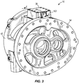
- Figs. 3 and 4 illustrate the compressor housing 42 and the valve 38 in more detail.
- the valve 38 is mounted (e.g., bolted, screwed, welded, etc.) directly to the compressor housing 42.
- the lubricant feed passageways 134, 138 are direct connections formed by aligning the outlets 122, 126 in the valve housing 110 with the ports 70, 74 in the compressor housing 42.
- the valve 38 may be coupled to, but spaced apart from the compressor housing 42.
- the lubricant feed passageways 134, 138 may be separate conduits or lines that extend between the valve housing 110 and the compressor housing 42.
- the spool 106 is movable within the cavity 114 relative to the valve housing 102 to selectively open and close (e.g., unblock and block) the outlets 122, 126.
- the spool 106 shuttles or slides to the first position to open the first outlet 122 and block the second outlet 126.
- the valve 38 fluidly connects the lubricant reservoir 30 to the first lubricant feed passageway 134 to direct lubricant to the first lubricant feed port 70.
- the spool 106 shuttles or slides to the second position to open the second outlet 126 and block the first outlet 122. In this position, the valve 38 fluidly connects the lubricant reservoir 30 to the second lubricant feed passageway 138 to direct lubricant to the second lubricant feed port 74.
- the spool 106 is actuated between the first and second positions based on a difference in pressure between a pressure at a first pressure region and a pressure at a second pressure region.
- the first pressure region includes the lubricant reservoir 30 and the second pressure region includes a portion of the compression chamber 58 adjacent the second lubricant feed port 74.
- the pressure in the lubricant reservoir 30 is substantially the same as the pressure at the discharge port 66 of the compressor 34.
- the spool 106 moves to the first position ( Fig.
- the valve housing 102 also defines a pilot inlet 146 in fluid communication with the compression chamber 58 via a pilot passageway 150.
- An orifice or restriction 152 is positioned in the pilot passageway 150 to limit fluid flow through the passageway 150. In some embodiments, the orifice 152 may be omitted.
- the pilot passageway 150 is schematically shown as being in fluid communication with the compression chamber 58 through the second lubricant feed port 74, the pilot passageway 150 is actually in fluid communication with the compression chamber 58 through a separate port that is generally parallel to, but spaced apart from the second lubricant feed port 74.
- the separate port is at the same relative distance from the suction port 62 in the direction of increasing pressure P as the second lubricant feed port 74, but offset transversely from the second lubricant feed port 74.
- the pilot inlet 146 communicates with the second lubricant feed port 74.
- the pilot inlet 146 directs a signal pressure from the compression chamber 58 into the cavity 114. This signal pressure enters the cavity 114 adjacent a first end 154 of the spool 106 (on the right side of the spool 106 in Figs. 1 and 2 ).
- the illustrated spool 106 includes a recessed annular portion 158 and a bleed hole 162 extending from the recessed portion 158 to a central region of the spool 106.
- the recessed portion 158 allows lubricant to flow into the cavity 114 of the valve housing 102 through the inlet 118.
- the recessed portion 158 also allows lubricant to flow around the spool 106 to the outlets 122, 126 and the bleed hole 162.
- the bleed hole 162 directs the lubricant toward a second end 166 of the spool 106 (on the left side of the spool 106 in Figs. 1 and 2 ).
- the pilot inlet 146 and the bleed hole 162 thereby establish pressures at the first end 154 and the second end 166 of the spool 106, respectively.
- the pilot inlet 146 directs fluid toward the right side of the illustrated spool 106 such that the pressure at the first end 154 of the spool 106 is generally equal to the pressure in the compression chamber 58 adjacent the second lubricant feed port 74 (i.e., the pressure at the second pressure region).
- the bleed hole 162 directs fluid toward the left side of the illustrated spool 106 such that the pressure at the second end 166 of the spool 106 is generally equal to the pressure in the lubricant reservoir 30 (i.e., the pressure at the first pressure region).
- the spool 106 shuttles or slides to the first position ( Fig. 1 ).
- the pressure at the second end 166 of the spool 106 exceeds the pressure at the first end 154 of the spool 106, the spool 106 shuttles or slides to the second position ( Fig. 2 ).
- the biasing member 110 is positioned within the valve housing 102 and coupled to the spool 106 to bias the spool 106 to the first position (to the left in Figs. 1 and 2 ).
- the biasing member 110 is a coil spring. In other embodiments, other suitable biasing members may also or alternatively be employed.
- the biasing member 110 inhibits premature movement of the spool 106 to the second position ( Fig. 2 ) if the pressure in the lubricant reservoir 30 is equal to or only slightly higher than the pressure in the compression chamber 58.
- the biasing member 110 also prepositions the valve 38 in the first position ( Fig. 1 ) at startup of the compression system 10.
- the motor 46 drives the shaft 82 of the drive rotor 50 to rotate the drive rotor 50 and the idler rotor 54.
- Fluid e.g., refrigerant
- the fluid is directed from the evaporator 26 into the compression chamber 58 of the screw compressor 34 through the suction port 62 in the compressor housing 42.
- the fluid is compressed by the rotors 50, 54 and moved in the direction of increasing pressure P from the suction port 62 to the discharge port 66, creating progressively increased pressure in the compression chamber 58.
- the fluid continues through the compression chamber 58 to the discharge port 66.
- the discharge port 66 directs the compressed fluid (e.g., refrigerant and lubricant) from the screw compressor 34 to the lubricant reservoir 30.
- the valve 38 is in the first position ( Fig. 1 ) to direct lubricant (e.g., oil) from the lubricant reservoir 30 to the first lubricant feed port 70.
- lubricant e.g., oil
- relatively low pressure lubricant is delivered to a low pressure section of the compression chamber 58 to lubricate the rotors 50, 54.
- Such an arrangement facilitates supplying lubricant to the rotors 50, 54 when the pressure of the lubricant is less than the pressure in the chamber 58 at the second lubricant feed port 74. Otherwise, the lubricant may be blown back through the second lubricant feed port 74.
- the valve 38 moves to the second position ( Fig. 2 ) to direct lubricant from the lubricant reservoir 30 to the second lubricant feed port 74. In this position, relatively high pressure lubricant is delivered to a higher pressure section of the compression chamber 58 to lubricate the rotors 50, 54.
- Such an arrangement increases efficiency of the compressor system 10 by supplying lubricant to the rotors 50, 54 at a location closer to the discharge port 66.
- the rotors 50, 54 may over-compress fluid in the compression chamber 58 such that the pressure in the chamber 58 is higher than the pressure of fluid being discharged to the reservoir 30.
- the pilot inlet 146 directs high pressure fluid from the compression chamber 58 into the cavity 114 of the valve 38 to move the valve 38 back to the first position ( Fig. 1 ) during these conditions.
- Lubricant is then directed from the lubricant reservoir 30 to the rotors 50, 54 through the first lubricant feed port 70, which is at a relatively lower pressure section of the compression chamber 58.
- FIGs. 5 and 6 illustrate another embodiment of a compressor system 210 for use with the refrigeration system 14.
- the illustrated compressor system 210 is similar to the compressor system 10 discussed above and like parts have been given the same reference numbers. Reference is hereby made to the compressor system 10 of Figs. 1-4 for discussion of features and elements of the compressor system 210, as well as alternatives to the features and elements, not specifically discussed below.
- the compressor housing 42 defines a bearing feed port 214.
- the bearing feed port 214 is in fluid communication with the bearings 94 adjacent the suction port 62.
- the compressor housing 42 may also define a bearing feed port in communication with the bearings 98 adjacent the discharge port 66.
- the bearing feed port 214 is in fluid communication with the valve 38 via a third lubricant feed passageway 222 to deliver lubricant to the bearings 94 when the valve 38 is in the first position.
- the bearing feed port 214 is in fluid communication with the valve 38 via a fourth lubricant feed passageway 226 to deliver lubricant to the bearings 94 when the valve 38 is in the second position.
- the lubricant feed passageways 222, 226 communicate with the cavity 114 of the valve 38 through outlets that are generally parallel to, but spaced apart from the first outlet 122 and the second outlet 126, respectively.
- An orifice or restriction 230, 232 is positioned in each passageway 222, 226 to limit lubricant flow through the passageways 222, 226.
- the second orifice 232 has a smaller diameter than the first orifice 230 such that less lubricant is supplied to the bearings 94 when the valve 38 is in the second position than when the valve 38 is in the first position.
- Such an arrangement increases the efficiency of the compressor system 10.
- the bearings 94 are flooded with lubricant through the orifice 230 to ensure proper lubrication for rotation of the rotors 50, 54.
- a smaller volume of lubricant can be supplied to the bearings 94 to maintain proper lubrication of the bearings 94.
- the smaller diameter of the second orifice 232 directs less lubricant to the bearings 94 than the orifice 230, thereby increasing the efficiency of the system 10.
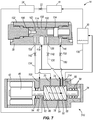
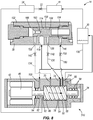
- Figs. 7 and 8 illustrate another embodiment of a compressor system 310 for use with the refrigeration system 14.
- the illustrated compressor system 310 is similar to the compressor system 10 discussed above and like parts have been given the same reference numbers. Reference is hereby made to the compressor system 10 of Figs. 1-4 for discussion of features and elements of the compressor system 310, as well as alternatives to the features and elements, not specifically discussed below.
- the valve 38 in the illustrated compressor system 310 moves between a first position ( Fig. 7 ) and a second position ( Fig. 8 ) based on a difference in pressure between a first pressure region and a second pressure region.
- the first pressure region includes the lubricant reservoir 30 and the second pressure region includes a portion of the compression chamber 58 downstream of the second lubricant feed port 74.
- the pilot inlet 146 of the valve 38 is in fluid communication with the compression chamber 58 of the screw compressor 34 through a port 314 located between the second lubricant feed port 74 and the discharge port 66. That is, the port 314 is located further along the compression chamber 58 than the second lubricant feed port 74 in the direction of increasing pressure P.
- the illustrated valve 38 does not include a biasing member (e.g., the biasing member 110 shown in Figs. 1 and 2 ) to bias the spool 106 to the first position ( Fig. 7 ). Instead, by positioning the port 314 between the second lubricant feed port 74 and the discharge port 66, the shuttle 106 does not move to the second position ( Fig. 8 ) until the pressure in the lubricant reservoir 30 is significantly greater than the pressure in the compression chamber 58 adjacent the second feed port 74. With such an arrangement, it is less likely that lubricant will be blown back through the second feed port 74 when the valve 38 is in the second position.
- the valve 38 may still include a biasing member or other element to preposition the shuttle 106 in the first position.
- the illustrated compressor system 310 may also include a bearing feed port similar to the bearing feed port 214 shown in Figs. 5 and 6 and discussed above.
- Figs. 9 and 10 illustrate another embodiment of a compressor system 410 for use with the refrigeration system 14.
- the illustrated compressor system 410 is similar to the compressor system 10 discussed above and like parts have been given the same reference numbers. Reference is hereby made to the compressor system 10 of Figs. 1-4 for discussion of features and elements of the compressor system 410, as well as alternatives to the features and elements, not specifically discussed below.
- the valve 38 in the illustrated compressor system 410 moves between a first position ( Fig. 9 ) and a second position ( Fig. 10 ) based on a difference in pressure between a first pressure region and a second pressure region.
- the first pressure region includes the lubricant reservoir 30 and the second pressure region includes the suction port 62 of the compression chamber 58.
- the spool 106 moves to the first position ( Fig. 9 ) when the pressure at the suction port 62 is greater than or equal to the pressure in the lubricant reservoir 30.
- the spool 106 moves to the second position ( Fig. 10 ) when the pressure in the lubricant reservoir 30 is greater than the pressure at the suction port 62 and the force of the biasing member 110.
- the illustrated compressor system 410 may also include a bearing feed port similar to the bearing feed port 214 shown in Figs. 5 and 6 and discussed above.
Landscapes
- Engineering & Computer Science (AREA)
- Mechanical Engineering (AREA)
- General Engineering & Computer Science (AREA)
- Applications Or Details Of Rotary Compressors (AREA)
Claims (15)
- Verdichtersystem (10), umfassend:einen Schmiermittelbehälter (30), der zur Aufnahme eines Schmiermittels geeignet ist;einen Schraubenverdichter (34), umfassendein Gehäuse (42), das eine Verdichtungskammer (58) mit einer Saugöffnung (62), einer Auslassöffnung (66), einer ersten Schmiermittelzufuhröffnung (70), die zwischen der Saugöffnung (62) und der Auslassöffnung (66) angeordnet ist, und einer zweiten Schmiermittelzufuhröffnung (74), die zwischen der Auslassöffnung (66) und der ersten Schmiermittelzufuhröffnung (70) angeordnet ist, definiert,einen Antriebsrotor (50), der durch das Gehäuse (42) getragen wird und in der Verdichtungskammer (58) angeordnet ist, undeinen durch das Gehäuse (42) getragenen und in der Verdichtungskammer (58) angeordneten Laufrotor (54), wobei der Laufrotor (54) durch den Antriebsrotor (50) angetrieben wird, um Fluid in einer Richtung zunehmenden Drucks von der Saugöffnung (62) zur Auslassöffnung (66) zu verdichten und zu bewegen und dabei einen Druck in einem ersten Druckbereich zu erzeugen; undgekennzeichnet durch ein Ventil (38) in Fluidverbindung mit dem Schmiermittelbehälter (30), wobei das Ventil (38) zwischen einer ersten Stellung und einer zweiten Stellung basierend auf dem Druck im ersten Druckbereich beweglich ist;wobei das Ventil (38) in der ersten Stellung den Schmiermittelbehälter (30) mit einem ersten Schmiermittelzufuhrdurchgang (134) fluidisch verbindet, um Schmiermittel über den ersten Schmiermittelzufuhrdurchgang (134) zur ersten Schmiermittelzufuhröffnung (70) zu leiten, und wobei das Ventil (38) in der zweiten Stellung den Schmiermittelbehälter (30) mit einem zweiten Schmiermittelzufuhrdurchgang (138) fluidisch verbindet, um Schmiermittel über den zweiten Schmiermittelzufuhrdurchgang (138) zur zweiten Schmiermittelzufuhröffnung (74) zu leiten.
- Verdichtersystem (10) nach Anspruch 1, wobei der Betrieb des Schraubenverdichters (34) den Druck im ersten Druckbereich erhöht, und wobei der erhöhte Druck im ersten Druckbereich das Ventil (38) aus der ersten Stellung in die zweite Stellung bewegt.
- Verdichtersystem (10) nach Anspruch 2, wobei das Ventil (38) ein Vorspannungselement (110) aufweist, um das Ventil (38) in die erste Stellung vorzuspannen, und wobei der erhöhte Druck im ersten Druckbereich das Vorspannungselement (110) überwindet, um das Ventil (38) in die zweite Stellung zu bewegen.
- Verdichtersystem (10) nach Anspruch 1, wobei das Ventil (38) ein Schieberventil (106) aufweist, und wobei der Druck im ersten Druckbereich das Schieberventil (106) zwischen der ersten Stellung und der zweiten Stellung mechanisch betätigt.
- Verdichtersystem (10) nach Anspruch 1, wobei der Laufrotor (54) durch den Antriebsrotor (50) angetrieben wird, um auch einen Druck in einem zweiten Druckbereich zu erzeugen, der von dem ersten Druckbereich beabstandet ist, und wobei das Ventil (38) zwischen der ersten Stellung und der zweiten Stellung basierend auf einer Druckdifferenz zwischen dem Druck im ersten Druckbereich und dem Druck im zweiten Druckbereich bewegt wird.
- Verdichtersystem (10) nach Anspruch 5, wobei der erste Druckbereich den Schmiermittelbehälter (30) und der zweite Druckbereich einen Abschnitt der Verdichtungskammer (58) angrenzend an die zweite Schmiermittelzufuhröffnung (74) aufweist.
- Verdichtersystem (10) nach Anspruch 6, wobei das Ventil (38) in die erste Stellung bewegt wird, wenn der Druck im Abschnitt der Verdichtungskammer (58) größer als der Druck im Schmiermittelbehälter (30) ist, und wobei das Ventil (38) in die zweite Stellung bewegt wird, wenn der Druck im Schmiermittelbehälter (30) größer als der Druck im Abschnitt der Verdichtungskammer (58) ist.
- Verdichtersystem (10) nach Anspruch 5, wobei der erste Druckbereich den Schmiermittelbehälter (30) und der zweite Druckbereich einen Abschnitt der Verdichtungskammer (58) zwischen der zweiten Schmiermittelzufuhröffnung (74) und der Auslassöffnung (66) aufweist, und gegebenenfalls
wobei das Ventil (38) in die erste Stellung bewegt wird, wenn der Druck im Abschnitt der Verdichtungskammer (58) größer als der Druck im Schmiermittelbehälter (30) ist, und wobei das Ventil (38) in die zweite Stellung bewegt wird, wenn der Druck im Schmiermittelbehälter (30) größer als der Druck im Abschnitt der Verdichtungskammer (58) ist. - Verdichtersystem (58) nach Anspruch 5, wobei der erste Druckbereich den Schmiermittelbehälter (30) und der zweite Druckbereich die Saugöffnung (62) der Verdichtungskammer (58) aufweist, und gegebenenfalls
wobei das Ventil (38) in die erste Stellung bewegt wird, wenn der Druck an der Saugöffnung (62) größer als der Druck am Schmiermittelbehälter (30) ist, und wobei das Ventil (38) in die zweite Stellung bewegt wird, wenn der Druck am Schmiermittelbehälter (30) größer als der Druck an der Saugöffnung (62) ist. - Verdichtersystem (10) nach Anspruch 1, wobei der Schraubenverdichter (34) ein Lager (94) aufweist, das einen des Antriebsrotors (50) und des Laufrotors (54) zur Rotation trägt, wobei das Gehäuse (42) das Lager (94) trägt und eine Lagerzufuhröffnung (214) definiert, die über einen dritten Schmiermittelzufuhrdurchgang (222) in Fluidverbindung mit dem Ventil (38) steht, und wobei das Ventil (38) den Schmiermittelbehälter (30) mit dem dritten Schmiermittelzufuhrdurchgang (222) fluidisch verbindet, um Schmiermittel zur Lagerzufuhröffnung (214) zu leiten, und gegebenenfalls, wobei das Ventil (38) in der ersten Stellung den Schmiermittelbehälter (30) mit dem dritten Schmiermittelzufuhrdurchgang (222) fluidisch verbindet, um Schmiermittel zur Lagerzufuhröffnung (214) zu leiten, und das Ventil (38) in der zweiten Stellung den Schmiermittelbehälter (30) mit einem vierten Schmiermittelzufuhrdurchgang (226) fluidisch verbindet, um Schmiermittel zur Lagerzufuhröffnung (214) zu leiten,
wobei der dritte Schmiermittelzufuhrdurchgang (222) eine erste Blende (230) und der vierte Schmiermittelzufuhrdurchgang (226) eine zweite Blende (232) aufweist, und
wobei die zweite Blende (232) einen kleineren Durchmesser als die erste Blende (230) aufweist, sodass dem Lager (94) weniger Schmiermittel zugeführt wird, wenn sich das Ventil (38) in der zweiten Stellung befindet, als wenn sich das Ventil (38) in der ersten Stellung befindet. - Verfahren zum Betreiben eines Verdichtersystems (10), wobei das Verdichtersystem (10) einen Schmiermittelbehälter (30), der zur Aufnahme eines Schmiermittels geeignet ist, und einen Schraubenverdichter (34) umfasst, wobei der Schraubenverdichter (34) ein Gehäuse (42) umfasst, das eine Verdichtungskammer (58) mit einer Saugöffnung (62), einer Auslassöffnung (66), einer ersten Schmiermittelzufuhröffnung (70), die sich zwischen der Ansaugöffnung (62) und der Auslassöffnung (66) befindet, und einer zweiten Schmiermittelzufuhröffnung (74), die sich zwischen der Auslassöffnung (62) und der ersten Schmiermittelzufuhröffnung (70) befindet, definiert, wobei das Verfahren umfasst:Bereitstellen eines Ventils (38) in Fluidverbindung mit dem Schmiermittelbehälter (30);Verdichten und Bewegen von Fluid in einer Richtung zunehmenden Drucks von der Saugöffnung (62) zur Auslassöffnung (66) und dabei Erzeugen eines Drucks in einem ersten Druckbereich; undgekennzeichnet durchBewegen des Ventils (38) zwischen einer ersten Stellung und einer zweiten Stellung basierend auf dem Druck im ersten Druckbereich;fluidisches Verbinden des Schmiermittelbehälters (30) mit einem ersten Schmiermittelzufuhrdurchgang (134), wenn sich das Ventil (38) in der ersten Stellung befindet, um Schmiermittel über den ersten Schmiermittelzufuhrdurchgang (134) an die erste Schmiermittelzufuhröffnung (70) des Schraubenverdichters (34) zu leiten; undfluidisches Verbinden des Schmiermittelbehälters (30) mit einem zweiten Schmiermittelzufuhrdurchgang (138), wenn sich das Ventil (38) in der zweiten Stellung befindet, um Schmiermittel über den zweiten Schmiermittelzufuhrdurchgang (138) an die zweite Schmiermittelzufuhröffnung (74) des Schraubenverdichters (34) zu leiten.
- Verfahren nach Anspruch 11, ferner umfassend Erhöhen des Drucks im ersten Druckbereich, um das Ventil (38) aus der ersten Stellung in die zweite Stellung zu bewegen, und gegebenenfalls ferner umfassend Vorspannen des Ventils (38) in die erste Stellung mit einem Vorspannungselement (110), und wobei das Erhöhen des Drucks im ersten Druckbereich das Erhöhen des Drucks im ersten Druckbereich umfasst, um das Vorspannungselement (110) zu überwinden und das Ventil (38) aus der ersten Stellung in die zweite Stellung zu bewegen.
- Verfahren nach Anspruch 11, wobei das Bereitstellen des Ventils (38) das Bereitstellen eines Schieberventils (106) umfasst, und wobei das Bewegen des Ventils (38) ein mechanisches Betätigen des Schieberventils (106) zwischen der ersten Stellung und der zweiten Stellung basierend auf dem Druck im ersten Druckbereich umfasst.
- Verfahren nach Anspruch 11, wobei das Verdichten und Bewegen von Fluid ein Verdichten und Bewegen von Fluid in Richtung eines Druckanstiegs von der Saugöffnung (62) zur Auslassöffnung (66) umfasst, wobei der Druck im ersten Druckbereich und ein Druck in einem zweiten Druckbereich, der vom ersten Druckbereich beabstandet ist, erzeugt wird, und wobei das Bewegen des Ventils (38) das Bewegen des Ventils (38) zwischen der ersten Stellung und der zweiten Stellung basierend auf einer Druckdifferenz zwischen dem Druck im ersten Druckbereich und dem Druck im zweiten Druckbereich umfasst.
- Verfahren nach Anspruch 11, wobei der Schraubenverdichter (34) ein Lager (94) aufweist, wobei das Gehäuse (42) das Lager (94) trägt und eine Lagerzufuhröffnung (214) definiert, wobei das Bereitstellen des Ventils (38) ein Bereitstellen des Ventils (38) in Fluidverbindung mit der Lagerzufuhröffnung über einen dritten Schmiermittelzufuhrdurchgang (222) umfasst, und ferner umfassend:fluidisches Verbinden des Schmiermittelbehälters (30) mit dem dritten Schmiermittelzufuhrdurchgang (222), um Schmiermittel zur Lagerzufuhröffnung (214) zu leiten, und gegebenenfallswobei das Bereitstellen des Ventils (38) auch das Bereitstellen des Ventils (38) in Fluidverbindung mit der Lagerzufuhröffnung (214) über einen vierten Schmiermittelzufuhrdurchgang (226) umfasst, wobei der dritte Schmiermittelzufuhrdurchgang (222) eine erste Blende (230) umfasst und der zweite Schmiermittelzufuhrdurchgang (138) eine zweite Blende (232) umfasst, und ferner umfassend:fluidisches Verbinden des Schmiermittelbehälters (30) mit dem vierten Schmiermittelzufuhrdurchgang (226), wenn sich das Ventil (38) in der zweiten Stellung befindet, um Schmiermittel zur Lagerzufuhröffnung (214) zu leiten,wobei die zweite Blende (232) einen kleineren Durchmesser als die erste Blende (230) aufweist, sodass dem Lager (94) weniger Schmiermittel zugeführt wird, wenn sich das Ventil (38) in der zweiten Stellung befindet, als wenn sich das Ventil (38) in der ersten Stellung befindet.
Applications Claiming Priority (2)
| Application Number | Priority Date | Filing Date | Title |
|---|---|---|---|
| US13/024,356 US8454334B2 (en) | 2011-02-10 | 2011-02-10 | Lubricant control valve for a screw compressor |
| PCT/US2012/024241 WO2012109302A2 (en) | 2011-02-10 | 2012-02-08 | Lubricant control valve for a screw compressor |
Publications (3)
| Publication Number | Publication Date |
|---|---|
| EP2673509A2 EP2673509A2 (de) | 2013-12-18 |
| EP2673509A4 EP2673509A4 (de) | 2015-09-02 |
| EP2673509B1 true EP2673509B1 (de) | 2020-04-01 |
Family
ID=46637012
Family Applications (1)
| Application Number | Title | Priority Date | Filing Date |
|---|---|---|---|
| EP12744795.1A Active EP2673509B1 (de) | 2011-02-10 | 2012-02-08 | Schmiermittelsteuerventil für einen schraubenverdichter |
Country Status (6)
| Country | Link |
|---|---|
| US (1) | US8454334B2 (de) |
| EP (1) | EP2673509B1 (de) |
| CN (1) | CN103459852B (de) |
| BR (1) | BR112013020408B1 (de) |
| CA (1) | CA2827100C (de) |
| WO (1) | WO2012109302A2 (de) |
Families Citing this family (27)
| Publication number | Priority date | Publication date | Assignee | Title |
|---|---|---|---|---|
| US8800688B2 (en) * | 2011-07-20 | 2014-08-12 | Baker Hughes Incorporated | Downhole motors with a lubricating unit for lubricating the stator and rotor |
| JP6779875B2 (ja) | 2014-11-11 | 2020-11-04 | トレイン インターナショナル インク | 冷媒組成物及び使用方法 |
| US9556372B2 (en) | 2014-11-26 | 2017-01-31 | Trane International Inc. | Refrigerant compositions |
| CN107002679B (zh) | 2014-12-17 | 2019-12-13 | 开利公司 | 具有油关闭阀的螺杆压缩机和方法 |
| JP6403027B2 (ja) * | 2015-02-26 | 2018-10-10 | 日立ジョンソンコントロールズ空調株式会社 | スクリュー圧縮機 |
| DE102015104914B4 (de) † | 2015-03-30 | 2021-09-23 | Gardner Denver Deutschland Gmbh | Kompressoranlage zur Erzeugung von Druckluft sowie Verfahren zum Betrieb einer Druckluft erzeugenden Kompressoranlage |
| JP6467324B2 (ja) * | 2015-09-29 | 2019-02-13 | 株式会社神戸製鋼所 | スクリュ圧縮機 |
| MX2018007039A (es) * | 2015-12-11 | 2018-08-15 | Atlas Copco Airpower Nv | Metodo para regular la inyeccion de liquido en un compresor, un compresor inyectado con liquido y un elemento compresor inyectado con liquido. |
| BE1023714B1 (nl) * | 2015-12-11 | 2017-06-26 | Atlas Copco Airpower Naamloze Vennootschap | Werkwijze voor het regelen van de vloeistofinjectie van een compressor- of expanderinrichting, een vloeistofgeïnjecteerde compressor- of expanderinrichting en een vloeistofgeïnjecteerd compressor- of expanderelement |
| EP3387257A1 (de) * | 2015-12-11 | 2018-10-17 | Atlas Copco Airpower | Verfahren zur regelung der flüssigkeitseinspritzung einer verdichter- oder expandervorrichtung, flüssigkeitseingespritzte verdichter- oder expandervorrichtung und flüssigkeitseingespritztes verdichter- oder expanderelement |
| US10386103B2 (en) * | 2015-12-17 | 2019-08-20 | Trane International Inc. | Suction conduit flow control for lubricant management |
| WO2018003211A1 (ja) * | 2016-06-28 | 2018-01-04 | 株式会社日立製作所 | 空気圧縮機 |
| BE1024462B1 (nl) * | 2016-08-01 | 2018-03-05 | Atlas Copco Airpower Naamloze Vennootschap | Vloeistofgeïnjecteerd compressor- of expanderelement en werkwijze voor het regelen van de vloeistofinjectie van een compressor- of expanderinrichting |
| US10527038B2 (en) * | 2017-01-20 | 2020-01-07 | Hamilton Sundstrand Corporation | Fuel flow control assembly of aircraft engine and method |
| JP7061618B2 (ja) * | 2017-04-07 | 2022-04-28 | スタックポール インターナショナル エンジニアード プロダクツ,リミテッド. | エピトロコイド真空ポンプ |
| US11118585B2 (en) * | 2017-10-04 | 2021-09-14 | Ingersoll-Rand Industrial U.S., Inc. | Screw compressor with oil injection at multiple volume ratios |
| US10876531B2 (en) * | 2018-12-26 | 2020-12-29 | Trane International Inc. | Lubricant injection for a screw compressor |
| EP3973190B1 (de) | 2019-05-20 | 2024-09-25 | Carrier Corporation | Kältemittelschraubenverdichter mit direktantrieb und mit kältemittel geschmierte lager |
| US20200378664A1 (en) * | 2019-05-31 | 2020-12-03 | Trane International Inc. | Lubricant management in an hvacr system |
| US11448220B2 (en) | 2019-09-27 | 2022-09-20 | Ingersoll-Rand Industrial U.S., Inc. | Airend having a lubricant flow valve and controller |
| GB2596608A (en) * | 2020-06-29 | 2022-01-05 | Leybold France S A S | Supplying lubricant to a lubricant sealed pump |
| DE102021201091A1 (de) * | 2021-02-05 | 2022-08-11 | Thyssenkrupp Ag | Verdichter, insbesondere Kältemittelverdichter, Kältemaschine, sowie Verfahren zur Herstellung eines Verdichters |
| CN113294332B (zh) * | 2021-07-22 | 2021-11-30 | 山东高原油气装备有限公司 | 一种油田开发用污油泥高效泵送的螺杆泵 |
| JP2025513081A (ja) * | 2022-04-13 | 2025-04-22 | アトラス コプコ (ウーシー) コンプレッサー カンパニー リミテッド | 圧縮機及び圧縮機を有する追加オイル噴射システム |
| JP7766567B2 (ja) * | 2022-08-15 | 2025-11-10 | 株式会社日立産機システム | 給液式スクリュー圧縮機 |
| CN117450077A (zh) * | 2023-10-24 | 2024-01-26 | 武汉纺织大学 | 一种用于螺杆式制冷压缩机即时供油的装置 |
| CN117536864A (zh) * | 2023-10-24 | 2024-02-09 | 武汉纺织大学 | 一种即时供油的螺杆式制冷压缩机装置 |
Family Cites Families (19)
| Publication number | Priority date | Publication date | Assignee | Title |
|---|---|---|---|---|
| DE1804884A1 (de) | 1968-10-24 | 1970-09-17 | Gutehoffnungshuette Sterkrade | Schraubenverdichter mit zwei ineinandergreifenden Schraubenrotoren und einem axialverstellbaren Steuerschieber zur Foerdermengenregelung und OEleinspritzung |
| GB1517156A (en) * | 1974-06-21 | 1978-07-12 | Svenska Rotor Maskiner Ab | Screw compressor including means for varying the capacity thereof |
| JPS52135407A (en) | 1976-05-06 | 1977-11-12 | Hitachi Ltd | Oil cooled rotary compressor |
| SE424760B (sv) | 1980-12-12 | 1982-08-09 | Sullair Tech Ab | Forfarande vid en oljeinsprutad skruvkompressor for balansering av axialkrafter hos atminstone en av kompressorns rotorer, for tetning av spalterna mellan rotorhus och rotorernas axlar, samt for kylning och smorjning .. |
| SE430709B (sv) * | 1982-04-30 | 1983-12-05 | Sullair Tech Ab | Skruvkompressor med anordning for reglering av inre kompressionen skruvkompressor med anordning for reglering av inre kompressionen |
| GB2159980B (en) * | 1982-09-10 | 1987-10-07 | Frick Co | Micro-processor control of compression ratio at full load in a helical screw rotary compressor responsive to compressor drive motor current |
| US4609329A (en) * | 1985-04-05 | 1986-09-02 | Frick Company | Micro-processor control of a movable slide stop and a movable slide valve in a helical screw rotary compressor with an enconomizer inlet port |
| JPH0631632B2 (ja) | 1987-01-19 | 1994-04-27 | 松下電器産業株式会社 | スクロ−ル気体圧縮機 |
| JPH02275089A (ja) | 1989-04-13 | 1990-11-09 | Kobe Steel Ltd | スクリュ式真空ポンプ |
| RU2073120C1 (ru) * | 1993-05-21 | 1997-02-10 | Акционерное общество "Научно-исследовательский и конструкторский институт центробежных и роторных компрессоров" | Винтовой компрессор |
| SE502631C2 (sv) * | 1994-04-19 | 1995-11-27 | Svenska Rotor Maskiner Ab | Skruvrotorkompressor med axialbalanseringsorgan |
| US5626470A (en) * | 1996-04-10 | 1997-05-06 | Ingersoll-Rand Company | Method for providing lubricant to thrust bearing |
| BE1010376A3 (nl) | 1996-06-19 | 1998-07-07 | Atlas Copco Airpower Nv | Rotatieve kompressor. |
| US6826926B2 (en) | 2002-01-07 | 2004-12-07 | Carrier Corporation | Liquid injection for reduced discharge pressure pulsation in compressors |
| BE1014611A3 (nl) * | 2002-02-08 | 2004-01-13 | Atlas Copco Airpower Nv | Werkwijze voor het besturen van de olieterugvoer in een met olie geinjecteerde schroefcompressor en aldus bestuurde schroefcompressor. |
| JP3916511B2 (ja) | 2002-06-03 | 2007-05-16 | 株式会社神戸製鋼所 | 油冷式圧縮機 |
| JP4110123B2 (ja) * | 2004-07-12 | 2008-07-02 | 株式会社神戸製鋼所 | スクリュ圧縮機 |
| JP5154469B2 (ja) | 2009-02-17 | 2013-02-27 | 日立オートモティブシステムズ株式会社 | 可変容量形ポンプ及びこれを用いたパワーステアリング装置 |
| CN201582109U (zh) * | 2009-09-11 | 2010-09-15 | 黄山工业泵制造有限公司 | 可调流量式螺杆泵 |
-
2011
- 2011-02-10 US US13/024,356 patent/US8454334B2/en active Active
-
2012
- 2012-02-08 WO PCT/US2012/024241 patent/WO2012109302A2/en not_active Ceased
- 2012-02-08 CA CA2827100A patent/CA2827100C/en active Active
- 2012-02-08 BR BR112013020408-7A patent/BR112013020408B1/pt active IP Right Grant
- 2012-02-08 EP EP12744795.1A patent/EP2673509B1/de active Active
- 2012-02-08 CN CN201280017224.2A patent/CN103459852B/zh active Active
Non-Patent Citations (1)
| Title |
|---|
| None * |
Also Published As
| Publication number | Publication date |
|---|---|
| WO2012109302A2 (en) | 2012-08-16 |
| US20120207634A1 (en) | 2012-08-16 |
| CN103459852B (zh) | 2016-03-30 |
| EP2673509A4 (de) | 2015-09-02 |
| CN103459852A (zh) | 2013-12-18 |
| BR112013020408A2 (pt) | 2016-10-25 |
| CA2827100A1 (en) | 2012-08-16 |
| US8454334B2 (en) | 2013-06-04 |
| EP2673509A2 (de) | 2013-12-18 |
| WO2012109302A3 (en) | 2012-11-01 |
| CA2827100C (en) | 2018-09-18 |
| BR112013020408B1 (pt) | 2021-03-30 |
Similar Documents
| Publication | Publication Date | Title |
|---|---|---|
| US8454334B2 (en) | Lubricant control valve for a screw compressor | |
| US10527041B2 (en) | Compressor having oil recovery means | |
| CN102734158B (zh) | 螺旋式压缩机及使用该螺旋式压缩机的冷风装置 | |
| US8641395B2 (en) | Compressor | |
| CN103362806B (zh) | 旋转叶片式压缩机 | |
| EP3084222B1 (de) | Verdichter mit variablem volumenindexventil | |
| US10288070B2 (en) | Screw compressor with oil shutoff and method | |
| EP3382205B1 (de) | Verdichter | |
| JP6606392B2 (ja) | 油冷式スクリュ圧縮機 | |
| US7690482B2 (en) | Screw compressor lubrication | |
| JP7350876B2 (ja) | 圧縮機本体及び圧縮機 | |
| JP2018021494A (ja) | スクリュー流体機械 | |
| CN105358840B (zh) | 涡轮压缩机及涡轮冷冻机 | |
| CN213116704U (zh) | 动涡旋装置和包括其的涡旋压缩机 | |
| US20150252806A1 (en) | Gas compressor | |
| US10876531B2 (en) | Lubricant injection for a screw compressor | |
| JP5844980B2 (ja) | 2段スクリュ圧縮式冷凍装置 | |
| EP3084216B1 (de) | Viskositätsverbesserung des schmiermittels eines kältemittelverdichters | |
| WO2007128308A1 (en) | Screw compressor with rotor endplates | |
| HK1117213B (en) | Screw compressor lubrication | |
| KR20070016126A (ko) | 압축기 윤활 | |
| HK1122859A1 (en) | Compressor lubrication | |
| HK1122859B (en) | Compressor lubrication |
Legal Events
| Date | Code | Title | Description |
|---|---|---|---|
| PUAI | Public reference made under article 153(3) epc to a published international application that has entered the european phase |
Free format text: ORIGINAL CODE: 0009012 |
|
| 17P | Request for examination filed |
Effective date: 20130809 |
|
| AK | Designated contracting states |
Kind code of ref document: A2 Designated state(s): AL AT BE BG CH CY CZ DE DK EE ES FI FR GB GR HR HU IE IS IT LI LT LU LV MC MK MT NL NO PL PT RO RS SE SI SK SM TR |
|
| DAX | Request for extension of the european patent (deleted) | ||
| A4 | Supplementary search report drawn up and despatched |
Effective date: 20150803 |
|
| RIC1 | Information provided on ipc code assigned before grant |
Ipc: F04C 29/12 20060101ALI20150728BHEP Ipc: F04C 18/16 20060101ALI20150728BHEP Ipc: F04C 29/00 20060101ALI20150728BHEP Ipc: F04C 29/02 20060101AFI20150728BHEP Ipc: F04C 2/107 20060101ALI20150728BHEP |
|
| GRAP | Despatch of communication of intention to grant a patent |
Free format text: ORIGINAL CODE: EPIDOSNIGR1 |
|
| STAA | Information on the status of an ep patent application or granted ep patent |
Free format text: STATUS: GRANT OF PATENT IS INTENDED |
|
| RIC1 | Information provided on ipc code assigned before grant |
Ipc: F04C 29/12 20060101ALI20190930BHEP Ipc: F04C 29/00 20060101ALI20190930BHEP Ipc: F04C 29/02 20060101AFI20190930BHEP Ipc: F04C 2/107 20060101ALI20190930BHEP Ipc: F04C 18/16 20060101ALI20190930BHEP |
|
| INTG | Intention to grant announced |
Effective date: 20191023 |
|
| GRAS | Grant fee paid |
Free format text: ORIGINAL CODE: EPIDOSNIGR3 |
|
| GRAA | (expected) grant |
Free format text: ORIGINAL CODE: 0009210 |
|
| STAA | Information on the status of an ep patent application or granted ep patent |
Free format text: STATUS: THE PATENT HAS BEEN GRANTED |
|
| AK | Designated contracting states |
Kind code of ref document: B1 Designated state(s): AL AT BE BG CH CY CZ DE DK EE ES FI FR GB GR HR HU IE IS IT LI LT LU LV MC MK MT NL NO PL PT RO RS SE SI SK SM TR |
|
| REG | Reference to a national code |
Ref country code: GB Ref legal event code: FG4D |
|
| REG | Reference to a national code |
Ref country code: AT Ref legal event code: REF Ref document number: 1251686 Country of ref document: AT Kind code of ref document: T Effective date: 20200415 Ref country code: CH Ref legal event code: EP |
|
| REG | Reference to a national code |
Ref country code: DE Ref legal event code: R096 Ref document number: 602012068908 Country of ref document: DE |
|
| REG | Reference to a national code |
Ref country code: IE Ref legal event code: FG4D |
|
| PG25 | Lapsed in a contracting state [announced via postgrant information from national office to epo] |
Ref country code: BG Free format text: LAPSE BECAUSE OF FAILURE TO SUBMIT A TRANSLATION OF THE DESCRIPTION OR TO PAY THE FEE WITHIN THE PRESCRIBED TIME-LIMIT Effective date: 20200701 |
|
| REG | Reference to a national code |
Ref country code: NL Ref legal event code: MP Effective date: 20200401 |
|
| REG | Reference to a national code |
Ref country code: LT Ref legal event code: MG4D |
|
| PG25 | Lapsed in a contracting state [announced via postgrant information from national office to epo] |
Ref country code: SE Free format text: LAPSE BECAUSE OF FAILURE TO SUBMIT A TRANSLATION OF THE DESCRIPTION OR TO PAY THE FEE WITHIN THE PRESCRIBED TIME-LIMIT Effective date: 20200401 Ref country code: IS Free format text: LAPSE BECAUSE OF FAILURE TO SUBMIT A TRANSLATION OF THE DESCRIPTION OR TO PAY THE FEE WITHIN THE PRESCRIBED TIME-LIMIT Effective date: 20200801 Ref country code: NO Free format text: LAPSE BECAUSE OF FAILURE TO SUBMIT A TRANSLATION OF THE DESCRIPTION OR TO PAY THE FEE WITHIN THE PRESCRIBED TIME-LIMIT Effective date: 20200701 Ref country code: CZ Free format text: LAPSE BECAUSE OF FAILURE TO SUBMIT A TRANSLATION OF THE DESCRIPTION OR TO PAY THE FEE WITHIN THE PRESCRIBED TIME-LIMIT Effective date: 20200401 Ref country code: NL Free format text: LAPSE BECAUSE OF FAILURE TO SUBMIT A TRANSLATION OF THE DESCRIPTION OR TO PAY THE FEE WITHIN THE PRESCRIBED TIME-LIMIT Effective date: 20200401 Ref country code: FI Free format text: LAPSE BECAUSE OF FAILURE TO SUBMIT A TRANSLATION OF THE DESCRIPTION OR TO PAY THE FEE WITHIN THE PRESCRIBED TIME-LIMIT Effective date: 20200401 Ref country code: GR Free format text: LAPSE BECAUSE OF FAILURE TO SUBMIT A TRANSLATION OF THE DESCRIPTION OR TO PAY THE FEE WITHIN THE PRESCRIBED TIME-LIMIT Effective date: 20200702 Ref country code: LT Free format text: LAPSE BECAUSE OF FAILURE TO SUBMIT A TRANSLATION OF THE DESCRIPTION OR TO PAY THE FEE WITHIN THE PRESCRIBED TIME-LIMIT Effective date: 20200401 Ref country code: PT Free format text: LAPSE BECAUSE OF FAILURE TO SUBMIT A TRANSLATION OF THE DESCRIPTION OR TO PAY THE FEE WITHIN THE PRESCRIBED TIME-LIMIT Effective date: 20200817 |
|
| REG | Reference to a national code |
Ref country code: AT Ref legal event code: MK05 Ref document number: 1251686 Country of ref document: AT Kind code of ref document: T Effective date: 20200401 |
|
| PG25 | Lapsed in a contracting state [announced via postgrant information from national office to epo] |
Ref country code: LV Free format text: LAPSE BECAUSE OF FAILURE TO SUBMIT A TRANSLATION OF THE DESCRIPTION OR TO PAY THE FEE WITHIN THE PRESCRIBED TIME-LIMIT Effective date: 20200401 Ref country code: RS Free format text: LAPSE BECAUSE OF FAILURE TO SUBMIT A TRANSLATION OF THE DESCRIPTION OR TO PAY THE FEE WITHIN THE PRESCRIBED TIME-LIMIT Effective date: 20200401 Ref country code: HR Free format text: LAPSE BECAUSE OF FAILURE TO SUBMIT A TRANSLATION OF THE DESCRIPTION OR TO PAY THE FEE WITHIN THE PRESCRIBED TIME-LIMIT Effective date: 20200401 |
|
| PG25 | Lapsed in a contracting state [announced via postgrant information from national office to epo] |
Ref country code: AL Free format text: LAPSE BECAUSE OF FAILURE TO SUBMIT A TRANSLATION OF THE DESCRIPTION OR TO PAY THE FEE WITHIN THE PRESCRIBED TIME-LIMIT Effective date: 20200401 |
|
| REG | Reference to a national code |
Ref country code: DE Ref legal event code: R097 Ref document number: 602012068908 Country of ref document: DE Ref country code: DE Ref legal event code: R082 Ref document number: 602012068908 Country of ref document: DE Representative=s name: HL KEMPNER PATENTANWALT, RECHTSANWALT, SOLICIT, DE Ref country code: DE Ref legal event code: R082 Ref document number: 602012068908 Country of ref document: DE Representative=s name: HL KEMPNER PATENTANWAELTE, SOLICITORS (ENGLAND, DE Ref country code: DE Ref legal event code: R082 Ref document number: 602012068908 Country of ref document: DE Representative=s name: HL KEMPNER PARTG MBB, DE |
|
| PG25 | Lapsed in a contracting state [announced via postgrant information from national office to epo] |
Ref country code: DK Free format text: LAPSE BECAUSE OF FAILURE TO SUBMIT A TRANSLATION OF THE DESCRIPTION OR TO PAY THE FEE WITHIN THE PRESCRIBED TIME-LIMIT Effective date: 20200401 Ref country code: IT Free format text: LAPSE BECAUSE OF FAILURE TO SUBMIT A TRANSLATION OF THE DESCRIPTION OR TO PAY THE FEE WITHIN THE PRESCRIBED TIME-LIMIT Effective date: 20200401 Ref country code: SM Free format text: LAPSE BECAUSE OF FAILURE TO SUBMIT A TRANSLATION OF THE DESCRIPTION OR TO PAY THE FEE WITHIN THE PRESCRIBED TIME-LIMIT Effective date: 20200401 Ref country code: EE Free format text: LAPSE BECAUSE OF FAILURE TO SUBMIT A TRANSLATION OF THE DESCRIPTION OR TO PAY THE FEE WITHIN THE PRESCRIBED TIME-LIMIT Effective date: 20200401 Ref country code: ES Free format text: LAPSE BECAUSE OF FAILURE TO SUBMIT A TRANSLATION OF THE DESCRIPTION OR TO PAY THE FEE WITHIN THE PRESCRIBED TIME-LIMIT Effective date: 20200401 Ref country code: AT Free format text: LAPSE BECAUSE OF FAILURE TO SUBMIT A TRANSLATION OF THE DESCRIPTION OR TO PAY THE FEE WITHIN THE PRESCRIBED TIME-LIMIT Effective date: 20200401 Ref country code: RO Free format text: LAPSE BECAUSE OF FAILURE TO SUBMIT A TRANSLATION OF THE DESCRIPTION OR TO PAY THE FEE WITHIN THE PRESCRIBED TIME-LIMIT Effective date: 20200401 |
|
| PLBE | No opposition filed within time limit |
Free format text: ORIGINAL CODE: 0009261 |
|
| STAA | Information on the status of an ep patent application or granted ep patent |
Free format text: STATUS: NO OPPOSITION FILED WITHIN TIME LIMIT |
|
| PG25 | Lapsed in a contracting state [announced via postgrant information from national office to epo] |
Ref country code: PL Free format text: LAPSE BECAUSE OF FAILURE TO SUBMIT A TRANSLATION OF THE DESCRIPTION OR TO PAY THE FEE WITHIN THE PRESCRIBED TIME-LIMIT Effective date: 20200401 Ref country code: SK Free format text: LAPSE BECAUSE OF FAILURE TO SUBMIT A TRANSLATION OF THE DESCRIPTION OR TO PAY THE FEE WITHIN THE PRESCRIBED TIME-LIMIT Effective date: 20200401 |
|
| 26N | No opposition filed |
Effective date: 20210112 |
|
| PG25 | Lapsed in a contracting state [announced via postgrant information from national office to epo] |
Ref country code: SI Free format text: LAPSE BECAUSE OF FAILURE TO SUBMIT A TRANSLATION OF THE DESCRIPTION OR TO PAY THE FEE WITHIN THE PRESCRIBED TIME-LIMIT Effective date: 20200401 |
|
| PG25 | Lapsed in a contracting state [announced via postgrant information from national office to epo] |
Ref country code: MC Free format text: LAPSE BECAUSE OF FAILURE TO SUBMIT A TRANSLATION OF THE DESCRIPTION OR TO PAY THE FEE WITHIN THE PRESCRIBED TIME-LIMIT Effective date: 20200401 |
|
| REG | Reference to a national code |
Ref country code: BE Ref legal event code: MM Effective date: 20210228 |
|
| PG25 | Lapsed in a contracting state [announced via postgrant information from national office to epo] |
Ref country code: CH Free format text: LAPSE BECAUSE OF NON-PAYMENT OF DUE FEES Effective date: 20210228 Ref country code: LU Free format text: LAPSE BECAUSE OF NON-PAYMENT OF DUE FEES Effective date: 20210208 Ref country code: LI Free format text: LAPSE BECAUSE OF NON-PAYMENT OF DUE FEES Effective date: 20210228 |
|
| PG25 | Lapsed in a contracting state [announced via postgrant information from national office to epo] |
Ref country code: IE Free format text: LAPSE BECAUSE OF NON-PAYMENT OF DUE FEES Effective date: 20210208 |
|
| PG25 | Lapsed in a contracting state [announced via postgrant information from national office to epo] |
Ref country code: BE Free format text: LAPSE BECAUSE OF NON-PAYMENT OF DUE FEES Effective date: 20210228 |
|
| PG25 | Lapsed in a contracting state [announced via postgrant information from national office to epo] |
Ref country code: HU Free format text: LAPSE BECAUSE OF FAILURE TO SUBMIT A TRANSLATION OF THE DESCRIPTION OR TO PAY THE FEE WITHIN THE PRESCRIBED TIME-LIMIT; INVALID AB INITIO Effective date: 20120208 Ref country code: CY Free format text: LAPSE BECAUSE OF FAILURE TO SUBMIT A TRANSLATION OF THE DESCRIPTION OR TO PAY THE FEE WITHIN THE PRESCRIBED TIME-LIMIT Effective date: 20200401 |
|
| P01 | Opt-out of the competence of the unified patent court (upc) registered |
Effective date: 20230505 |
|
| PG25 | Lapsed in a contracting state [announced via postgrant information from national office to epo] |
Ref country code: MK Free format text: LAPSE BECAUSE OF FAILURE TO SUBMIT A TRANSLATION OF THE DESCRIPTION OR TO PAY THE FEE WITHIN THE PRESCRIBED TIME-LIMIT Effective date: 20200401 |
|
| PG25 | Lapsed in a contracting state [announced via postgrant information from national office to epo] |
Ref country code: MT Free format text: LAPSE BECAUSE OF FAILURE TO SUBMIT A TRANSLATION OF THE DESCRIPTION OR TO PAY THE FEE WITHIN THE PRESCRIBED TIME-LIMIT Effective date: 20200401 |
|
| PG25 | Lapsed in a contracting state [announced via postgrant information from national office to epo] |
Ref country code: TR Free format text: LAPSE BECAUSE OF FAILURE TO SUBMIT A TRANSLATION OF THE DESCRIPTION OR TO PAY THE FEE WITHIN THE PRESCRIBED TIME-LIMIT Effective date: 20200401 |
|
| PGFP | Annual fee paid to national office [announced via postgrant information from national office to epo] |
Ref country code: GB Payment date: 20260121 Year of fee payment: 15 |
|
| PGFP | Annual fee paid to national office [announced via postgrant information from national office to epo] |
Ref country code: DE Payment date: 20260121 Year of fee payment: 15 |
|
| PGFP | Annual fee paid to national office [announced via postgrant information from national office to epo] |
Ref country code: FR Payment date: 20260121 Year of fee payment: 15 |