EP2673859B1 - Einrichtung mit zwei parallel geschalteten batterien - Google Patents
Einrichtung mit zwei parallel geschalteten batterien Download PDFInfo
- Publication number
- EP2673859B1 EP2673859B1 EP12703320.7A EP12703320A EP2673859B1 EP 2673859 B1 EP2673859 B1 EP 2673859B1 EP 12703320 A EP12703320 A EP 12703320A EP 2673859 B1 EP2673859 B1 EP 2673859B1
- Authority
- EP
- European Patent Office
- Prior art keywords
- batteries
- voltage
- current
- battery
- control
- Prior art date
- Legal status (The legal status is an assumption and is not a legal conclusion. Google has not performed a legal analysis and makes no representation as to the accuracy of the status listed.)
- Not-in-force
Links
Images




Classifications
-
- H—ELECTRICITY
- H02—GENERATION; CONVERSION OR DISTRIBUTION OF ELECTRIC POWER
- H02H—EMERGENCY PROTECTIVE CIRCUIT ARRANGEMENTS
- H02H3/00—Emergency protective circuit arrangements for automatic disconnection directly responsive to an undesired change from normal electric working condition with or without subsequent reconnection ; integrated protection
- H02H3/20—Emergency protective circuit arrangements for automatic disconnection directly responsive to an undesired change from normal electric working condition with or without subsequent reconnection ; integrated protection responsive to excess voltage
- H02H3/207—Emergency protective circuit arrangements for automatic disconnection directly responsive to an undesired change from normal electric working condition with or without subsequent reconnection ; integrated protection responsive to excess voltage also responsive to under-voltage
-
- H—ELECTRICITY
- H02—GENERATION; CONVERSION OR DISTRIBUTION OF ELECTRIC POWER
- H02H—EMERGENCY PROTECTIVE CIRCUIT ARRANGEMENTS
- H02H9/00—Emergency protective circuit arrangements for limiting excess current or voltage without disconnection
- H02H9/02—Emergency protective circuit arrangements for limiting excess current or voltage without disconnection responsive to excess current
- H02H9/025—Current limitation using field effect transistors
-
- H—ELECTRICITY
- H02—GENERATION; CONVERSION OR DISTRIBUTION OF ELECTRIC POWER
- H02H—EMERGENCY PROTECTIVE CIRCUIT ARRANGEMENTS
- H02H7/00—Emergency protective circuit arrangements specially adapted for specific types of electric machines or apparatus or for sectionalised protection of cable or line systems, and effecting automatic switching in the event of an undesired change from normal working conditions
- H02H7/18—Emergency protective circuit arrangements specially adapted for specific types of electric machines or apparatus or for sectionalised protection of cable or line systems, and effecting automatic switching in the event of an undesired change from normal working conditions for batteries; for accumulators
-
- H—ELECTRICITY
- H02—GENERATION; CONVERSION OR DISTRIBUTION OF ELECTRIC POWER
- H02J—ELECTRIC POWER NETWORKS; CIRCUIT ARRANGEMENTS OR SYSTEMS FOR SUPPLYING OR DISTRIBUTING ELECTRIC POWER; SYSTEMS FOR STORING ELECTRIC ENERGY
- H02J7/00—Circuit arrangements for charging or discharging batteries or for supplying loads from batteries
- H02J7/50—Circuit arrangements for charging or discharging batteries or for supplying loads from batteries acting upon multiple batteries simultaneously or sequentially
- H02J7/52—Circuit arrangements for charging or discharging batteries or for supplying loads from batteries acting upon multiple batteries simultaneously or sequentially for charge balancing, e.g. equalisation of charge between batteries
-
- H—ELECTRICITY
- H02—GENERATION; CONVERSION OR DISTRIBUTION OF ELECTRIC POWER
- H02J—ELECTRIC POWER NETWORKS; CIRCUIT ARRANGEMENTS OR SYSTEMS FOR SUPPLYING OR DISTRIBUTING ELECTRIC POWER; SYSTEMS FOR STORING ELECTRIC ENERGY
- H02J7/00—Circuit arrangements for charging or discharging batteries or for supplying loads from batteries
- H02J7/50—Circuit arrangements for charging or discharging batteries or for supplying loads from batteries acting upon multiple batteries simultaneously or sequentially
- H02J7/52—Circuit arrangements for charging or discharging batteries or for supplying loads from batteries acting upon multiple batteries simultaneously or sequentially for charge balancing, e.g. equalisation of charge between batteries
- H02J7/54—Passive balancing, e.g. using resistors or parallel MOSFETs
Definitions
- the present invention relates to the technical field of devices for protecting voltage sources against overcurrent currents.
- the invention relates to an installation comprising two batteries connected in parallel.
- the invention also relates to a method of operating such an installation.
- a protection fuse is conventionally used to interrupt a abnormally high current but it does not answer the problem since it is irreversible.
- the object of the invention is to provide an installation for overcoming the problems mentioned above and improving the known installations of the prior art.
- the invention proposes a simple protection installation, consuming very little energy, having a very low electrical resistance and making it possible to avoid current peaks while effectively protecting voltage sources against overcurrents.
- This invention applies to any voltage source such as batteries, voltage supplies, DC-DC converters.
- the control means of the controlled switch may use voltage information across the coil to control the state of the controlled switch.
- the controlled switch control means may utilize voltage information across the resistive element to control the state of the controlled switch.
- the controlled switch control means may utilize voltage information across the first set including the coil and the resistive element to control the state of the controlled switch.
- the controlled switch may be a power transistor, in particular a field effect MOS transistor.
- the control means may comprise a driving transistor of the power transistor.
- the control means may comprise a voltage comparator.
- a series assembly in opposition of two Zener diodes may be arranged in parallel with the coil.
- the installation may comprise a second protection device, the controlled switch of each of the first and second devices being a power transistor, in particular a field-effect MOS transistor, the first and second devices being arranged in series and the transistors the first and second protective devices being connected to each other symmetrically.
- a second protection device the controlled switch of each of the first and second devices being a power transistor, in particular a field-effect MOS transistor, the first and second devices being arranged in series and the transistors the first and second protective devices being connected to each other symmetrically.
- the second device may comprise a second parallel assembly comprising a second controlled switch and a second resistive element.
- the control means of the first and second controlled switches may use voltage information across a set of coil and / or first and / or second resistive elements.
- a method of operation of a previously defined installation comprises the use of voltage information across the coil to control the state of the controlled switch.
- the closing of the controlled switch can be controlled when the absolute value of the voltage between the two batteries, in particular the absolute value of the voltage at the terminals of an assembly comprising the coil and the resistive element, becomes lower than a first threshold. .
- the opening of the controlled switch can be controlled when the absolute value of the voltage between the two batteries, in particular the absolute value of the voltage at the terminals of an assembly comprising the coil and the resistive element, becomes greater than a second one. threshold.
- the principle of a protection device 1 according to the invention is represented at figure 1 . It allows the parallel connection of two batteries 10 and 20 while ensuring that during this connection, the intensity of the electric current passing through the batteries will not be too high in case the battery voltages are not equal.
- the protection device 1 according to the invention is associated with a battery 10, that is to say that a battery device 150 according to the invention comprises a battery 10 and a protection device according to the invention .
- the protection device makes it possible to protect the battery against rapid and large amplitude variations in the current (inrush current), ie against overcurrents.
- This protection device is powered by the battery with which it is associated and has a very low consumption (preferably a lower consumption than the self discharge of the battery with which it is associated). Furthermore, the protection device has a very low series resistance (preferably a series resistance lower than the internal resistance of the battery with which it is associated). The intrinsic performances of the battery with which it is associated are thus not altered by the circuit.
- the protection device is intended to be mounted in series with the battery with which it is associated.
- an installation 100 comprises two batteries connected in parallel with the aid of a protection device 1.
- a second circuit 2 may be arranged between the two other terminals of the batteries to be connected.
- a first embodiment of a protection device 1 is described below with reference to FIG. figure 2 , the protection device being arranged between two batteries 10, 20.
- the controlled switches are MOS field effect transistors connected by their drains.
- the gates of these switches are connected to ground through resistors 62 and 63.
- a control circuit 61 included in the control means 6 controls the states of the transistors, in particular as a function of the difference in electrical potential between the two terminals A and B to be connected.
- links connect this control circuit to these terminals.
- the control means comprises the control circuit and the resistors 62 and 63.
- the resistor 43 is then inserted into the circuit between the terminals A and B of the batteries in the first case and the resistor 42 is then inserted into the circuit between terminals A and B of the batteries in the second case.
- Resistors 42 and 43 are sized to limit the current flowing between the two batteries. In doing so, they maintain the DeltaV potential difference beyond the action of the coil and until the voltages of the two batteries are balanced.
- the control circuit then maintains the control of the transistors until that moment.
- the balancing threshold can be set. Then, the control of the transistors is released and the circuit returns to its initial position, the two transistors being conductive and the resistors 42 and 43 being short-circuited.
- the circuit mainly comprises two bipolar transistors 612 and 613: a first transistor 612 whose base is connected to the terminal A to be connected to the first battery 10 through a parallel mounting of a resistor 622 and a capacitor 632, the emitter is connected to a terminal B to be connected to the second battery and the collector is connected to ground through resistor 62, and a second transistor 613 whose base is connected to terminal B to be connected to the second battery 20 through a parallel mounting of a resistor 623 and a capacitor 633, the emitter is connected to the terminal A to be connected to the first battery and the collector is connected to ground through the resistor 63.
- Zener diodes D1 and D2 may be mounted in opposition in parallel with the coil. Thus, the voltage across the coil is limited in a first direction of current flow at the Zener voltage of the diode D1 and is limited in a second direction of current flow at the Zener voltage of the diode D2.
- the limit of this device is related to the minimum control voltage of transistors 612 and 613 which corresponds to the minimum voltage of the base / transmitter junction, that is to say about 0.6V. In the case of battery connections, this limit may be insufficient if it generates a current that is too high.
- Such a protection device has a very low energy consumption since it is reduced to the control of MOS field effect transistors.
- the resulting current is much lower than the self-discharge of the batteries.
- Such an embodiment is reserved in case a potential difference of 0.6V does not generate excessive current for the batteries.
- This is the situation of a battery assembly in series of sufficiently high voltage.
- this circuit may be suitable for a higher or lower final voltage of a set of batteries.
- a voltage difference between the batteries less than a value equal to twice the internal resistance value of a battery multiplied by a current
- the maximum allowed battery power is bearable in most cases when connecting parallel. This value is of the order of a few percent of the nominal voltage of the assembly for standard batteries.
- a second embodiment of device 1 'of protection according to the invention is described below with reference to the figure 4 .
- This embodiment differs from the first embodiment shown in FIG. figure 3 by the structure of the control circuit 61 '.
- the circuit mainly comprises two bipolar transistors 612 'and 613'.
- the collector of transistor 612 ' is connected to ground through resistor 62.
- the emitter of transistor 612' is connected to the terminal of resistor 42 not common to resistor 43.
- the base of transistor 612 ' is connected to the output of a comparator 652 through a Zener diode D4 and a resistor R6 connected in series.
- the comparator compares the potential of the terminal A of the first battery to a voltage obtained by a voltage divider R11, R12 from the potential of the terminal B of the second battery.
- the collector of transistor 613 ' is connected to ground through resistor 63.
- the emitter of transistor 613' is connected to the terminal of resistor 43 not common to resistor 42.
- the base of transistor 613 ' is connected to the output of a comparator 653 through a Zener diode D3 and a resistor R5 connected in series.
- the comparator compares the potential of the terminal B of the first battery to a voltage obtained by a voltage divider R9, R10 from the potential of the terminal A of the first battery.
- the voltage dividers allow a DeltaVmin trip threshold to be defined by a division ratio of the voltages V1 and V2.
- the following three cases are to be distinguished:
- the outputs of the comparators 652 and 653 are in the high state and the transistors 612 'and 613' are off. Transistors 52 and 53 are on and short circuit the current limiting resistors. The impedance path between the two batteries is very low (2 ⁇ Rdson + RI, with RI the resistance of the coil).
- the output of the comparator 653 is low and the transistor 613 'is on.
- the transistor 53 is blocked and the limiting resistor 43 is turned on.
- the impedance path between the two batteries causes a current limitation due to the presence of the resistor 43.
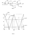
- the output of the comparator 652 is low and the transistor 612 'is activated.
- the transistor 52 is off and the limiting resistor 42 is turned on.
- the impedance path between the two batteries causes a current limitation due to the presence of the resistor 42.
- Zener diodes D1 and D2 make it possible to limit the overvoltage that appears at the terminals of the coil when the limiting resistors (R3 or R4) are switched on or off.
- Zener diodes D3 and D4, and resistors R5 and R6 allow the control of transistors 612 'and 613'.
- the fault detection threshold can be lowered without limitation. For proper operation, however, it must not not be less than the noise level.
- the use of the comparators induces additional consumption, however components of very low consumption make it possible to obtain currents lower than the self-discharge of the battery in many cases.
- This second embodiment is adapted for example to low voltage batteries and high capacity, when the first embodiment is not usable. More precisely, this second embodiment is used if the response of the circuit RL formed by the coil and the internal resistances of the batteries induces a current too great for an excitation at a voltage step of 0.6V, the value of the voltage difference for which the limiting resistor is disconnected using the first embodiment.
- the effects of the device according to the invention are described below using modelizations.
- the batteries are modeled as having a certain capacity (model V, i, t); what is done for the sake of convenience by means of a capacitor charged to the same voltage as the battery.
- the two current trends are represented on the graph of the figure 10 .
- a current measurement could be performed using a shunt or a Hall effect sensor.
- the shunt would remain permanently connected, which would result in additional losses in "normal" battery usage.
- the Hall sensor is a fairly expensive component that requires a particular power supply.
- the voltage V_AB is used to power the control electronics of the MOS transistors 52 and 53.
- This electronics is just to depolarize the gates of the MOS transistors 52 and 53, when the voltages of the batteries are different, which adds resistance. limitation between the two batteries. Thus, when the battery voltages are equalized, the control electronics consumes nothing.
- control circuit 6 The operation of the control circuit 6 is described below with reference to the figure 12 .
- the voltage signal V_AB measured or determined across a set 90 comprising the coil and the limiting resistor is provided to a delay operator 200 (reflecting the time required for a field effect MOS transistor to switch). At the output of this operator, the signal is transformed at an operator of absolute value 210. The positive signal that comes out is then provided to two comparators to compare the two-threshold positive signal.
- the output of the first comparator 220 is connected to a SET input of an RS flip-flop 240.
- the output of the second comparator 230 is connected to a RESET input of the RS flip-flop 240.
- the Q output signal of the RS flip-flop 240 constitutes the signal control of the controlled switch.
- each battery is modeled by a capacitor charged to the battery voltage and can restore the same energy as the battery and which is added a series resistance to model the internal resistance of the battery.
- the evolution of this performance as a function of the voltage V2 of the second battery is illustrated on the graph of the figure 18 for a voltage value V1 of the first battery equal to 20 V.
- the efficiency varies from 0.5 to 1 for a voltage V2 varying in the interval [0, V1].
- the efficiency does not depend on the current limiting resistor. There are always the same losses, the energy being dissipated in the internal resistances of the batteries when there is no limiting resistance.
- the coil is dimensioned so as to involve the protection device during a fast current variation, a first criterion of speed to be defined.
- This first criterion is determined by the response times of the switch and its control means. It defines the low value of the inductance of the coil: the current must not vary too much between the moment of the detection of the overcurrent and the moment of the opening of the switch.
- the high value of the inductance of the coil depends on the dynamics of the application envisaged: the faster the current variations imposed by the application, the lower the value of the inductance of the coil.
- a coil inductance close to the low value is chosen.
- the resistance of the coil must be as low as possible.
- the coil must also at least withstand the current supported by the batteries.
- the current limiting resistors 42, 43 are sized to limit the current to an acceptable value for the batteries in the worst case voltage difference scenario, i.e. when a fully charged battery is connected. to a completely discharged battery. If short-circuit protection is desired, the battery voltage and the maximum acceptable current for the resistance calculation must be taken into account.
- ⁇ Vmax Vbat (battery voltage) and the maximum acceptable current must be considered for the calculation of the resistance.
- Resistors 62 and 63 are polarization resistors of MOS field effect transistors.
- the capacitors 632 and 633 of the first embodiment allow a greater reactivity of the circuit during a fault due to too high current and / or a too sudden change in current.
- the controlled switches 52 and 53 must withstand the maximum current of the batteries in the on state and have the lowest Rdson resistance possible. They must also have a short response time so as to use a coil of low inductance value.
- Polarization transistors 612, 613, 612 ', 613' are small bipolar switching transistors.
- Zener diodes limit the overvoltage across the coil when switching the controlled switch.
- the resistors R9 and R10 on the one hand and the resistors R11 and R12 on the other hand form dividing bridges for setting a trigger threshold of the protection device.
- the comparators 652, 653 must have the shortest possible response time for the reactivity of the circuit and allow a low dimensioning of the inductance of the coil.
- Zener diodes D3 and D4 serve to bias transistors 612, 612 ', 613, 613'.
- a 2Ah (NimH) battery has an internal resistance of about 25 mOhms and a maximum discharge current of 1 A.
- the resistors 42 and 43 may be replaced by resettable fuses of polyswitch type of smaller size and lower cost than a resistance solution. Functionally, this variant is the equivalent of a resettable fuse with very low resistance of rest.
- the protection device according to the invention can be used in all cases where it is necessary to protect a voltage source against a strong current draw, that is to say any application that requires protection against overcurrent or short circuit. -circuit with low online losses. In addition to paralleling batteries, it can be used to prevent a short circuit or limit a current draw for certain loads (heating, lighting, radio ).
- the device In the case of a short circuit of the battery, the device remains active until the disappearance of the short circuit or the complete discharge of the battery (and the current is limited by the resistor 43).
Landscapes
- Engineering & Computer Science (AREA)
- Power Engineering (AREA)
- Charge And Discharge Circuits For Batteries Or The Like (AREA)
- Secondary Cells (AREA)
Claims (14)
- Anlage (100; 100'), die zwei mit Hilfe einer ersten Schutzvorrichtung (1; 1') einer Spannungsquelle (10; 20) parallel geschaltete Batterien enthält, die enthält:- eine parallele Einheit, die einen gesteuerten Schalter (5; 52, 53) und ein Widerstandselement (4; 42, 43) enthält,- eine Spule (3), die zwischen den zwei Batterien mit der Einheit in Reihe geschaltet ist,- eine Steuereinrichtung (6) des Schalters der Einheit, die abhängig von der Spannungsdifferenz (V_AB) zwischen den zwei Batterien so gesteuert wird, dass der gesteuerte Schalter geschlossen ist, wenn die Spannungsdifferenz niedriger als eine erste Schwelle (Schwelle 1) wird, und dass der gesteuerte Schalter offen ist, wenn die Spannungsdifferenz höher als eine zweite Schwelle (Schwelle 2) wird.
- Anlage nach dem vorhergehenden Anspruch, dadurch gekennzeichnet, dass die Steuereinrichtung des gesteuerten Schalters eine Spannungsinformation an den Klemmen der Spule verwendet, um den Zustand des gesteuerten Schalters zu steuern.
- Anlage nach Anspruch 1 oder 2, dadurch gekennzeichnet, dass die Steuereinrichtung des gesteuerten Schalters eine Spannungsinformation an den Klemmen des Widerstandselements verwendet, um den Zustand des gesteuerten Schalters zu steuern.
- Anlage nach einem der vorhergehenden Ansprüche, dadurch gekennzeichnet, dass die Steuereinrichtung des gesteuerten Schalters eine Spannungsinformation an den Klemmen der die Spule und das Widerstandselement enthaltenden Einheit verwendet, um den Zustand des gesteuerten Schalters zu steuern.
- Anlage nach einem der vorhergehenden Ansprüche, dadurch gekennzeichnet, dass der gesteuerte Schalter ein Leistungstransistor, insbesondere ein MOS-Feldeffekttransistor ist.
- Anlage nach dem vorhergehenden Anspruch, dadurch gekennzeichnet, dass die Steuereinrichtung einen Transistor (612, 613; 612', 613') zur Steuerung des Leistungstransistors enthält.
- Anlage nach einem der vorhergehenden Ansprüche, dadurch gekennzeichnet, dass die Steuereinrichtung einen Spannungskomparator (652, 653) enthält.
- Anlage nach einem der vorhergehenden Ansprüche, dadurch gekennzeichnet, dass sie eine Gegenreihenschaltungseinheit von zwei Zener-Dioden parallel zur Spule enthält.
- Anlage nach einem der vorhergehenden Ansprüche, dadurch gekennzeichnet, dass sie eine zweite Schutzvorrichtung enthält, wobei der gesteuerte Schalter jeder der ersten und zweiten Vorrichtungen ein Leistungstransistor ist, insbesondere ein MOS-Feldeffekttransistor, wobei die ersten und zweiten Vorrichtungen in Reihe geschaltet und die Leistungstransistoren der ersten und zweiten Schutzvorrichtungen symmetrisch miteinander verbunden sind.
- Anlage nach dem vorhergehenden Anspruch, dadurch gekennzeichnet, dass die zweite Vorrichtung eine zweite parallele Einheit enthält, die einen zweiten gesteuerten Schalter und eine zweites Widerstandselement enthält.
- Anlage nach dem vorhergehenden Anspruch, dadurch gekennzeichnet, dass die Steuereinrichtung der ersten und zweiten gesteuerten Schalter eine Spannungsinformation an den Klemmen einer aus der Spule und/oder den ersten und/oder zweiten Widerstandselementen bestehenden Einheit verwendet.
- Betriebsverfahren einer Anlage nach einem der Ansprüche 1 bis 11, dadurch gekennzeichnet, dass eine Spannungsinformation zwischen den zwei Batterien verwendet wird, um den Zustand des gesteuerten Schalters zu steuern.
- Betriebsverfahren nach dem vorhergehenden Anspruch, dadurch gekennzeichnet, dass das Schließen des gesteuerten Schalters gesteuert wird, wenn der Absolutwert der Spannung zwischen den zwei Batterien niedriger wird als eine erste Schwelle (Schwelle 1).
- Betriebsverfahren nach Anspruch 12 oder 13, dadurch gekennzeichnet, dass das Öffnen des gesteuerten Schalter gesteuert wird, wenn der Absolutwert der Spannung zwischen den zwei Batterien höher wird als eine zweite Schwelle (Schwelle 2).
Applications Claiming Priority (2)
| Application Number | Priority Date | Filing Date | Title |
|---|---|---|---|
| FR1151068A FR2971645B1 (fr) | 2011-02-10 | 2011-02-10 | Dispositif de protection d'une source de tension contre les surintensites de courant |
| PCT/EP2012/052365 WO2012107586A1 (fr) | 2011-02-10 | 2012-02-10 | Installation comprenant deux batteries raccordées en parallèle |
Publications (2)
| Publication Number | Publication Date |
|---|---|
| EP2673859A1 EP2673859A1 (de) | 2013-12-18 |
| EP2673859B1 true EP2673859B1 (de) | 2015-03-18 |
Family
ID=44515200
Family Applications (1)
| Application Number | Title | Priority Date | Filing Date |
|---|---|---|---|
| EP12703320.7A Not-in-force EP2673859B1 (de) | 2011-02-10 | 2012-02-10 | Einrichtung mit zwei parallel geschalteten batterien |
Country Status (4)
| Country | Link |
|---|---|
| US (1) | US9350160B2 (de) |
| EP (1) | EP2673859B1 (de) |
| FR (1) | FR2971645B1 (de) |
| WO (1) | WO2012107586A1 (de) |
Families Citing this family (8)
| Publication number | Priority date | Publication date | Assignee | Title |
|---|---|---|---|---|
| JP6119143B2 (ja) * | 2011-11-01 | 2017-04-26 | 日産自動車株式会社 | 電源の制御装置 |
| CN106451623B (zh) * | 2016-10-14 | 2020-07-03 | 宁德时代新能源科技股份有限公司 | 热插拔方法及热插拔控制装置、电压平衡方法及装置 |
| GB201705518D0 (en) | 2017-04-05 | 2017-05-17 | Siemens Ag | Energy storage module |
| US10797482B2 (en) * | 2017-07-31 | 2020-10-06 | National Oilwell Varco, L.P. | Active limiting circuit for intrinsically safe equipment |
| CN113809812B (zh) * | 2020-06-12 | 2025-02-25 | 北京小米移动软件有限公司 | 双电池电路及其控制方法、电子设备 |
| US12136837B1 (en) * | 2020-12-08 | 2024-11-05 | Bobbie Wilson | Charge balancing of parallel strings with zener diode and light emitting diode between cell terminal of the battery strings |
| US11641117B2 (en) * | 2021-02-08 | 2023-05-02 | Motorola Mobility Llc | Electronic devices with multiple energy storage device charging circuits and corresponding methods |
| DE102021210296A1 (de) * | 2021-09-16 | 2023-03-16 | Vitesco Technologies Germany Gmbh | Verfahren zum Überwachen der Integrität eines Steuergeräts |
Family Cites Families (12)
| Publication number | Priority date | Publication date | Assignee | Title |
|---|---|---|---|---|
| FR2663168B1 (fr) * | 1990-06-06 | 1992-11-13 | Matthelec Mediterranee Sa | Procede et dispositif de limitation des surintensites dans un circuit electrique. |
| US5696659A (en) | 1993-02-10 | 1997-12-09 | Maruo; Masaya | Overcurrent protective circuit and semiconductor device |
| TW265482B (de) | 1994-06-01 | 1995-12-11 | Siemens Akitengesellschaft | |
| US7145313B2 (en) * | 2004-06-29 | 2006-12-05 | Motorola Inc. | Battery protection circuit for simulating an overcurrent condition based on battery current flow |
| TWI317184B (en) * | 2006-07-17 | 2009-11-11 | Compal Electronics Inc | A hybrid battery module with a voltage balance unit and its charging and discharging method |
| KR100824888B1 (ko) * | 2006-08-22 | 2008-04-23 | 삼성에스디아이 주식회사 | 하이브리드 배터리 팩 및 그것의 충전 방법과 방전 방법 |
| JP5155701B2 (ja) * | 2008-03-12 | 2013-03-06 | 富士重工業株式会社 | 車両用電源装置 |
| US8174242B2 (en) * | 2008-04-10 | 2012-05-08 | Iks Co., Ltd. | Apparatus and method for pre-charging in charging/discharging equipment for an energy-storage device |
| US7915859B2 (en) | 2008-05-07 | 2011-03-29 | Lg Electronics Inc. | Apparatus and method for controlling power |
| DE102008060936A1 (de) * | 2008-12-06 | 2010-06-10 | Daimler Ag | Vorrichtung und Verfahren zum Betreiben einer Batterieeinheit eines Kraftfahrzeugs |
| US8823323B2 (en) * | 2009-04-16 | 2014-09-02 | Valence Technology, Inc. | Batteries, battery systems, battery submodules, battery operational methods, battery system operational methods, battery charging methods, and battery system charging methods |
| JP5143185B2 (ja) * | 2010-02-08 | 2013-02-13 | 三洋電機株式会社 | 電源装置 |
-
2011
- 2011-02-10 FR FR1151068A patent/FR2971645B1/fr not_active Expired - Fee Related
-
2012
- 2012-02-10 WO PCT/EP2012/052365 patent/WO2012107586A1/fr not_active Ceased
- 2012-02-10 EP EP12703320.7A patent/EP2673859B1/de not_active Not-in-force
- 2012-02-10 US US13/984,671 patent/US9350160B2/en not_active Expired - Fee Related
Also Published As
| Publication number | Publication date |
|---|---|
| FR2971645B1 (fr) | 2014-02-28 |
| US9350160B2 (en) | 2016-05-24 |
| WO2012107586A1 (fr) | 2012-08-16 |
| EP2673859A1 (de) | 2013-12-18 |
| FR2971645A1 (fr) | 2012-08-17 |
| US20130329327A1 (en) | 2013-12-12 |
Similar Documents
| Publication | Publication Date | Title |
|---|---|---|
| EP2673859B1 (de) | Einrichtung mit zwei parallel geschalteten batterien | |
| EP1685622B1 (de) | Gleichgewichts-ladeverfahren für eine lithiumionen- oder lithiumpolymerbatterie | |
| EP1854165B3 (de) | Verfahren zum ausgewogenen aufladen einer lithiumionen- oder lithium-polymer-batterie | |
| EP4189411B1 (de) | System zur verwaltung einer halbmodularen akkumulatorbatterie | |
| EP3105845B1 (de) | Gleichspannungsversorgungssystem zur vorladung eines glättungskondensators vor der speisung einer last | |
| EP4189406B1 (de) | Batterieverwaltungssystem | |
| EP3060422B1 (de) | Schutz einer stromversorgung mit mehreren parallel geschalteten batterien gegen äusseren kurzschluss | |
| WO2011003924A1 (fr) | Batterie d'accumulateurs a pertes reduites | |
| WO2013072358A1 (fr) | Batterie d'accumulateurs protegee contre les courts-circuits internes | |
| EP1381131B1 (de) | Verbesserte Schutzeinrichtung mit 1S Schaltungen für elektrochemische Batterienanordnungen | |
| FR3055495A1 (fr) | Procede et dispositif de circuit pour couper une source de tension d'au moins un consommateur | |
| EP2088674B1 (de) | Regel und Schutzsystem für einen Low-Side Schalter einer Automatisierungseinrichtung | |
| EP1083645B1 (de) | Elektronischer Auslöser mit Initialisierungseinrichtung | |
| FR2908939A1 (fr) | Dispositif de commande pour assurer la regulation en tension d'un bus d'alimentation. | |
| EP0678962B1 (de) | Elektronischer Auslöser mit Speichervorrichtung | |
| EP3883077B1 (de) | Geräte zum elektrischen schutz und entsprechende verfahren | |
| EP3894278B1 (de) | Vorrichtung zum vorladen eines stromnetzes | |
| FR2474776A1 (fr) | Appareil pour la charge d'une batterie rechargeable | |
| WO2025021873A1 (fr) | Circuit de commande de disjonction pour système de gestion des accumulateurs de batterie et système de gestion des accumulateurs de batterie équipé d'un tel circuit | |
| FR3131383A1 (fr) | Système de contrôle d’une pluralité de cellules de batterie et batterie associée | |
| EP0141698B1 (de) | Stromdetektorschaltung mit niedrigem Leistungsverbrauch und Steuerschaltung einer mit ihr bestückten elektronischen Anordnung | |
| FR2843245A1 (fr) | Dispositif et procede de protection d'un composant electronique contre des surcharges dommageables | |
| FR3065589A1 (fr) | Systeme de protection contre la foudre et les court-circuits d'un equipement electrique embarque dans un aeronef | |
| FR3077689A1 (fr) | Methode et dispositif pour detection de depassement d'un seuil de temperature predefini. | |
| FR2877153A1 (fr) | Montage d'alimentation electrique d'une serrure electromagnetique et ensemble correspondant |
Legal Events
| Date | Code | Title | Description |
|---|---|---|---|
| PUAI | Public reference made under article 153(3) epc to a published international application that has entered the european phase |
Free format text: ORIGINAL CODE: 0009012 |
|
| 17P | Request for examination filed |
Effective date: 20130910 |
|
| AK | Designated contracting states |
Kind code of ref document: A1 Designated state(s): AL AT BE BG CH CY CZ DE DK EE ES FI FR GB GR HR HU IE IS IT LI LT LU LV MC MK MT NL NO PL PT RO RS SE SI SK SM TR |
|
| DAX | Request for extension of the european patent (deleted) | ||
| GRAP | Despatch of communication of intention to grant a patent |
Free format text: ORIGINAL CODE: EPIDOSNIGR1 |
|
| RIC1 | Information provided on ipc code assigned before grant |
Ipc: H02J 7/00 20060101ALI20140926BHEP Ipc: H02H 7/18 20060101ALN20140926BHEP Ipc: H02H 9/02 20060101AFI20140926BHEP |
|
| INTG | Intention to grant announced |
Effective date: 20141014 |
|
| GRAS | Grant fee paid |
Free format text: ORIGINAL CODE: EPIDOSNIGR3 |
|
| GRAA | (expected) grant |
Free format text: ORIGINAL CODE: 0009210 |
|
| AK | Designated contracting states |
Kind code of ref document: B1 Designated state(s): AL AT BE BG CH CY CZ DE DK EE ES FI FR GB GR HR HU IE IS IT LI LT LU LV MC MK MT NL NO PL PT RO RS SE SI SK SM TR |
|
| REG | Reference to a national code |
Ref country code: GB Ref legal event code: FG4D Free format text: NOT ENGLISH |
|
| REG | Reference to a national code |
Ref country code: CH Ref legal event code: EP |
|
| REG | Reference to a national code |
Ref country code: IE Ref legal event code: FG4D Free format text: LANGUAGE OF EP DOCUMENT: FRENCH |
|
| REG | Reference to a national code |
Ref country code: AT Ref legal event code: REF Ref document number: 717112 Country of ref document: AT Kind code of ref document: T Effective date: 20150415 |
|
| REG | Reference to a national code |
Ref country code: DE Ref legal event code: R096 Ref document number: 602012005983 Country of ref document: DE Effective date: 20150430 |
|
| REG | Reference to a national code |
Ref country code: NL Ref legal event code: VDEP Effective date: 20150318 |
|
| REG | Reference to a national code |
Ref country code: NL Ref legal event code: VDEP Effective date: 20150318 |
|
| PG25 | Lapsed in a contracting state [announced via postgrant information from national office to epo] |
Ref country code: HR Free format text: LAPSE BECAUSE OF FAILURE TO SUBMIT A TRANSLATION OF THE DESCRIPTION OR TO PAY THE FEE WITHIN THE PRESCRIBED TIME-LIMIT Effective date: 20150318 Ref country code: LT Free format text: LAPSE BECAUSE OF FAILURE TO SUBMIT A TRANSLATION OF THE DESCRIPTION OR TO PAY THE FEE WITHIN THE PRESCRIBED TIME-LIMIT Effective date: 20150318 Ref country code: SE Free format text: LAPSE BECAUSE OF FAILURE TO SUBMIT A TRANSLATION OF THE DESCRIPTION OR TO PAY THE FEE WITHIN THE PRESCRIBED TIME-LIMIT Effective date: 20150318 Ref country code: FI Free format text: LAPSE BECAUSE OF FAILURE TO SUBMIT A TRANSLATION OF THE DESCRIPTION OR TO PAY THE FEE WITHIN THE PRESCRIBED TIME-LIMIT Effective date: 20150318 Ref country code: NO Free format text: LAPSE BECAUSE OF FAILURE TO SUBMIT A TRANSLATION OF THE DESCRIPTION OR TO PAY THE FEE WITHIN THE PRESCRIBED TIME-LIMIT Effective date: 20150618 |
|
| REG | Reference to a national code |
Ref country code: AT Ref legal event code: MK05 Ref document number: 717112 Country of ref document: AT Kind code of ref document: T Effective date: 20150318 |
|
| REG | Reference to a national code |
Ref country code: LT Ref legal event code: MG4D |
|
| PG25 | Lapsed in a contracting state [announced via postgrant information from national office to epo] |
Ref country code: RS Free format text: LAPSE BECAUSE OF FAILURE TO SUBMIT A TRANSLATION OF THE DESCRIPTION OR TO PAY THE FEE WITHIN THE PRESCRIBED TIME-LIMIT Effective date: 20150318 Ref country code: GR Free format text: LAPSE BECAUSE OF FAILURE TO SUBMIT A TRANSLATION OF THE DESCRIPTION OR TO PAY THE FEE WITHIN THE PRESCRIBED TIME-LIMIT Effective date: 20150619 Ref country code: LV Free format text: LAPSE BECAUSE OF FAILURE TO SUBMIT A TRANSLATION OF THE DESCRIPTION OR TO PAY THE FEE WITHIN THE PRESCRIBED TIME-LIMIT Effective date: 20150318 |
|
| PG25 | Lapsed in a contracting state [announced via postgrant information from national office to epo] |
Ref country code: NL Free format text: LAPSE BECAUSE OF FAILURE TO SUBMIT A TRANSLATION OF THE DESCRIPTION OR TO PAY THE FEE WITHIN THE PRESCRIBED TIME-LIMIT Effective date: 20150318 |
|
| PG25 | Lapsed in a contracting state [announced via postgrant information from national office to epo] |
Ref country code: RO Free format text: LAPSE BECAUSE OF FAILURE TO SUBMIT A TRANSLATION OF THE DESCRIPTION OR TO PAY THE FEE WITHIN THE PRESCRIBED TIME-LIMIT Effective date: 20150318 Ref country code: EE Free format text: LAPSE BECAUSE OF FAILURE TO SUBMIT A TRANSLATION OF THE DESCRIPTION OR TO PAY THE FEE WITHIN THE PRESCRIBED TIME-LIMIT Effective date: 20150318 Ref country code: CZ Free format text: LAPSE BECAUSE OF FAILURE TO SUBMIT A TRANSLATION OF THE DESCRIPTION OR TO PAY THE FEE WITHIN THE PRESCRIBED TIME-LIMIT Effective date: 20150318 Ref country code: SK Free format text: LAPSE BECAUSE OF FAILURE TO SUBMIT A TRANSLATION OF THE DESCRIPTION OR TO PAY THE FEE WITHIN THE PRESCRIBED TIME-LIMIT Effective date: 20150318 Ref country code: PT Free format text: LAPSE BECAUSE OF FAILURE TO SUBMIT A TRANSLATION OF THE DESCRIPTION OR TO PAY THE FEE WITHIN THE PRESCRIBED TIME-LIMIT Effective date: 20150720 Ref country code: ES Free format text: LAPSE BECAUSE OF FAILURE TO SUBMIT A TRANSLATION OF THE DESCRIPTION OR TO PAY THE FEE WITHIN THE PRESCRIBED TIME-LIMIT Effective date: 20150318 |
|
| PG25 | Lapsed in a contracting state [announced via postgrant information from national office to epo] |
Ref country code: PL Free format text: LAPSE BECAUSE OF FAILURE TO SUBMIT A TRANSLATION OF THE DESCRIPTION OR TO PAY THE FEE WITHIN THE PRESCRIBED TIME-LIMIT Effective date: 20150318 Ref country code: AT Free format text: LAPSE BECAUSE OF FAILURE TO SUBMIT A TRANSLATION OF THE DESCRIPTION OR TO PAY THE FEE WITHIN THE PRESCRIBED TIME-LIMIT Effective date: 20150318 Ref country code: IS Free format text: LAPSE BECAUSE OF FAILURE TO SUBMIT A TRANSLATION OF THE DESCRIPTION OR TO PAY THE FEE WITHIN THE PRESCRIBED TIME-LIMIT Effective date: 20150718 |
|
| REG | Reference to a national code |
Ref country code: DE Ref legal event code: R097 Ref document number: 602012005983 Country of ref document: DE |
|
| PG25 | Lapsed in a contracting state [announced via postgrant information from national office to epo] |
Ref country code: IT Free format text: LAPSE BECAUSE OF FAILURE TO SUBMIT A TRANSLATION OF THE DESCRIPTION OR TO PAY THE FEE WITHIN THE PRESCRIBED TIME-LIMIT Effective date: 20150318 |
|
| PLBE | No opposition filed within time limit |
Free format text: ORIGINAL CODE: 0009261 |
|
| STAA | Information on the status of an ep patent application or granted ep patent |
Free format text: STATUS: NO OPPOSITION FILED WITHIN TIME LIMIT |
|
| PG25 | Lapsed in a contracting state [announced via postgrant information from national office to epo] |
Ref country code: DK Free format text: LAPSE BECAUSE OF FAILURE TO SUBMIT A TRANSLATION OF THE DESCRIPTION OR TO PAY THE FEE WITHIN THE PRESCRIBED TIME-LIMIT Effective date: 20150318 |
|
| 26N | No opposition filed |
Effective date: 20151221 |
|
| PG25 | Lapsed in a contracting state [announced via postgrant information from national office to epo] |
Ref country code: SI Free format text: LAPSE BECAUSE OF FAILURE TO SUBMIT A TRANSLATION OF THE DESCRIPTION OR TO PAY THE FEE WITHIN THE PRESCRIBED TIME-LIMIT Effective date: 20150318 |
|
| REG | Reference to a national code |
Ref country code: FR Ref legal event code: PLFP Year of fee payment: 5 |
|
| PG25 | Lapsed in a contracting state [announced via postgrant information from national office to epo] |
Ref country code: BE Free format text: LAPSE BECAUSE OF NON-PAYMENT OF DUE FEES Effective date: 20160229 |
|
| PG25 | Lapsed in a contracting state [announced via postgrant information from national office to epo] |
Ref country code: LU Free format text: LAPSE BECAUSE OF FAILURE TO SUBMIT A TRANSLATION OF THE DESCRIPTION OR TO PAY THE FEE WITHIN THE PRESCRIBED TIME-LIMIT Effective date: 20160210 Ref country code: MC Free format text: LAPSE BECAUSE OF FAILURE TO SUBMIT A TRANSLATION OF THE DESCRIPTION OR TO PAY THE FEE WITHIN THE PRESCRIBED TIME-LIMIT Effective date: 20150318 |
|
| REG | Reference to a national code |
Ref country code: CH Ref legal event code: PL |
|
| PG25 | Lapsed in a contracting state [announced via postgrant information from national office to epo] |
Ref country code: CH Free format text: LAPSE BECAUSE OF NON-PAYMENT OF DUE FEES Effective date: 20160229 Ref country code: LI Free format text: LAPSE BECAUSE OF NON-PAYMENT OF DUE FEES Effective date: 20160229 |
|
| REG | Reference to a national code |
Ref country code: IE Ref legal event code: MM4A |
|
| PG25 | Lapsed in a contracting state [announced via postgrant information from national office to epo] |
Ref country code: IE Free format text: LAPSE BECAUSE OF NON-PAYMENT OF DUE FEES Effective date: 20160210 |
|
| REG | Reference to a national code |
Ref country code: FR Ref legal event code: PLFP Year of fee payment: 6 |
|
| PGFP | Annual fee paid to national office [announced via postgrant information from national office to epo] |
Ref country code: DE Payment date: 20170210 Year of fee payment: 6 Ref country code: FR Payment date: 20170228 Year of fee payment: 6 |
|
| PGFP | Annual fee paid to national office [announced via postgrant information from national office to epo] |
Ref country code: GB Payment date: 20170214 Year of fee payment: 6 |
|
| PG25 | Lapsed in a contracting state [announced via postgrant information from national office to epo] |
Ref country code: MT Free format text: LAPSE BECAUSE OF FAILURE TO SUBMIT A TRANSLATION OF THE DESCRIPTION OR TO PAY THE FEE WITHIN THE PRESCRIBED TIME-LIMIT Effective date: 20150318 |
|
| PG25 | Lapsed in a contracting state [announced via postgrant information from national office to epo] |
Ref country code: SM Free format text: LAPSE BECAUSE OF FAILURE TO SUBMIT A TRANSLATION OF THE DESCRIPTION OR TO PAY THE FEE WITHIN THE PRESCRIBED TIME-LIMIT Effective date: 20150318 Ref country code: CY Free format text: LAPSE BECAUSE OF FAILURE TO SUBMIT A TRANSLATION OF THE DESCRIPTION OR TO PAY THE FEE WITHIN THE PRESCRIBED TIME-LIMIT Effective date: 20150318 Ref country code: HU Free format text: LAPSE BECAUSE OF FAILURE TO SUBMIT A TRANSLATION OF THE DESCRIPTION OR TO PAY THE FEE WITHIN THE PRESCRIBED TIME-LIMIT; INVALID AB INITIO Effective date: 20120210 |
|
| PG25 | Lapsed in a contracting state [announced via postgrant information from national office to epo] |
Ref country code: TR Free format text: LAPSE BECAUSE OF FAILURE TO SUBMIT A TRANSLATION OF THE DESCRIPTION OR TO PAY THE FEE WITHIN THE PRESCRIBED TIME-LIMIT Effective date: 20150318 Ref country code: MK Free format text: LAPSE BECAUSE OF FAILURE TO SUBMIT A TRANSLATION OF THE DESCRIPTION OR TO PAY THE FEE WITHIN THE PRESCRIBED TIME-LIMIT Effective date: 20150318 |
|
| PG25 | Lapsed in a contracting state [announced via postgrant information from national office to epo] |
Ref country code: BG Free format text: LAPSE BECAUSE OF FAILURE TO SUBMIT A TRANSLATION OF THE DESCRIPTION OR TO PAY THE FEE WITHIN THE PRESCRIBED TIME-LIMIT Effective date: 20150318 |
|
| REG | Reference to a national code |
Ref country code: DE Ref legal event code: R119 Ref document number: 602012005983 Country of ref document: DE |
|
| GBPC | Gb: european patent ceased through non-payment of renewal fee |
Effective date: 20180210 |
|
| PG25 | Lapsed in a contracting state [announced via postgrant information from national office to epo] |
Ref country code: AL Free format text: LAPSE BECAUSE OF FAILURE TO SUBMIT A TRANSLATION OF THE DESCRIPTION OR TO PAY THE FEE WITHIN THE PRESCRIBED TIME-LIMIT Effective date: 20150318 |
|
| REG | Reference to a national code |
Ref country code: FR Ref legal event code: ST Effective date: 20181031 |
|
| PG25 | Lapsed in a contracting state [announced via postgrant information from national office to epo] |
Ref country code: DE Free format text: LAPSE BECAUSE OF NON-PAYMENT OF DUE FEES Effective date: 20180901 |
|
| PG25 | Lapsed in a contracting state [announced via postgrant information from national office to epo] |
Ref country code: GB Free format text: LAPSE BECAUSE OF NON-PAYMENT OF DUE FEES Effective date: 20180210 Ref country code: FR Free format text: LAPSE BECAUSE OF NON-PAYMENT OF DUE FEES Effective date: 20180228 |