EP2674030A2 - Eierband - Google Patents
Eierband Download PDFInfo
- Publication number
- EP2674030A2 EP2674030A2 EP13164091.4A EP13164091A EP2674030A2 EP 2674030 A2 EP2674030 A2 EP 2674030A2 EP 13164091 A EP13164091 A EP 13164091A EP 2674030 A2 EP2674030 A2 EP 2674030A2
- Authority
- EP
- European Patent Office
- Prior art keywords
- recesses
- egg
- conveying direction
- holes
- triangular
- Prior art date
- Legal status (The legal status is an assumption and is not a legal conclusion. Google has not performed a legal analysis and makes no representation as to the accuracy of the status listed.)
- Granted
Links
Images




Classifications
-
- B—PERFORMING OPERATIONS; TRANSPORTING
- B65—CONVEYING; PACKING; STORING; HANDLING THIN OR FILAMENTARY MATERIAL
- B65G—TRANSPORT OR STORAGE DEVICES, e.g. CONVEYORS FOR LOADING OR TIPPING, SHOP CONVEYOR SYSTEMS OR PNEUMATIC TUBE CONVEYORS
- B65G15/00—Conveyors having endless load-conveying surfaces, i.e. belts and like continuous members, to which tractive effort is transmitted by means other than endless driving elements of similar configuration
- B65G15/30—Belts or like endless load-carriers
- B65G15/58—Belts or like endless load-carriers with means for holding or retaining the loads in fixed position, e.g. magnetic
-
- A—HUMAN NECESSITIES
- A01—AGRICULTURE; FORESTRY; ANIMAL HUSBANDRY; HUNTING; TRAPPING; FISHING
- A01K—ANIMAL HUSBANDRY; AVICULTURE; APICULTURE; PISCICULTURE; FISHING; REARING OR BREEDING ANIMALS, NOT OTHERWISE PROVIDED FOR; NEW BREEDS OF ANIMALS
- A01K31/00—Housing birds
- A01K31/14—Nest-boxes, e.g. for singing birds or the like
- A01K31/16—Laying nests for poultry; Egg collecting
- A01K31/165—Egg collecting or counting
-
- B—PERFORMING OPERATIONS; TRANSPORTING
- B65—CONVEYING; PACKING; STORING; HANDLING THIN OR FILAMENTARY MATERIAL
- B65G—TRANSPORT OR STORAGE DEVICES, e.g. CONVEYORS FOR LOADING OR TIPPING, SHOP CONVEYOR SYSTEMS OR PNEUMATIC TUBE CONVEYORS
- B65G2201/00—Indexing codes relating to handling devices, e.g. conveyors, characterised by the type of product or load being conveyed or handled
- B65G2201/02—Articles
- B65G2201/0202—Agricultural and processed food products
- B65G2201/0208—Eggs
Definitions
- the invention relates to an egg belt comprising a conveyor belt extending in a direction for conveying eggs in a conveying direction and a plurality of recesses.
- Egg bands are used in egg production for transporting eggs in a conveying direction, for example when transporting laying hen cages to packaging stations.
- Egg bands are often endless belts that have a main direction of extension that matches the direction of conveyance. Parallel to the main extension direction or conveying direction, an egg belt is bounded by two edges or edges, as well as transversely to the main extension direction or conveying direction by two edges or ends.
- Egg bands can be used in various conveyor systems and driven by various means to transport eggs in the conveying direction.
- an egg belt referred to above which is characterized in that the recesses are triangular in shape.
- the inventive design of the recesses as triangles has several advantages over the known in the prior art recesses of the egg bands.
- a first advantage is that in the inventive design of the egg belt with triangular recesses or holes, an egg with a portion of its surface is immersed in such a triangular recess and thereby at three points, ie one point per triangle side, is supported by the band.
- This three-point bearing of the eggs on the egg belt is much more stable than when stored in circular, square or rectangular recesses. In this way, with the egg belt according to the invention a relative movement between the eggs and the band can be further reduced.
- the triangular recesses of the invention have the further advantage that annular contamination on the eggs can be avoided.
- annular contaminants are particularly conspicuous and therefore disadvantageous.
- an egg Due to the triangular design of the recesses, an egg is preferably independent of its orientation always only with three places on the egg belt, ie per side surface of a triangular recess there is a point of contact with the egg. In this way, only punctiform pollution spots instead of circular pollution rings arise.
- the design with triangular recesses also has the advantage that a higher stability of the egg is given, especially in tensile stresses of the egg belt in the conveying direction and shear stresses in the conveyor belt level, not parallel to the conveying direction at tensile loads but at an angle thereto occur.
- the effect can occur that the squares or rectangles warp into parallelograms and this deformation is opposed by little resistance by the egg tape structure.
- the inventive design of the recesses in the form of triangles is compared to such tensile and shear stresses a much higher stability.
- the contamination of the eggs can thus be significantly reduced because compared to an annular or at least 4-point-shaped storage of the egg in the inventive 3-point storage, there is only a minimum number of required contact points between the egg and the egg belt and thus, the transfer of dirt from the egg belt to the egg over existing webs via the contact points is reduced. Furthermore, the egg belt according to the invention has a higher stability against tensile and shear stresses.
- a higher hole proportion per band section, d. H. a minimized surface can be realized, so that dirt or dust can only be deposited on the remaining or minimized surface and therefore there is less dirt overall on an egg belt according to the invention. This also contributes to less pollution of the eggs.
- the recesses or holes in the band are preferably arranged in a regular pattern. In this way, the stability of the tape can be further increased.
- the recesses are formed as isosceles triangles. This further development form has the advantage of a particularly high stability of the egg-belt and an improved storage of eggs over known egg-bands.
- the triangular recesses may have rounded corners. This has the advantage that less dirt can settle in the corners of the triangles and therefore the contamination of the eggs can be further reduced.
- the triangular recesses each circumscribe a circle with a diameter of 15 to 25 mm, in particular 20 mm.
- triangles can be achieved that the eggs sink in the recesses as deep as in known egg bands with circular recesses, d. H. the egg dives through the band just as deep as in conventional egg bands.
- a triangular-shaped recess which circumscribes a circle with a certain diameter, is larger than the corresponding circular recess with the same diameter.
- these larger triangular recesses more dirt can thus fall through than through the smaller circular recesses.
- the surface can be further reduced compared to known egg bands, so that less dirt and dust can accumulate on the egg belt and the pollution of the eggs is reduced, while at the same time ensuring that the eggs do not sag too deeply through the tape.
- the size of the triangles is selected so that an egg, regardless of its orientation, only comes into contact with the eggbond at three points, in particular each with a location of a side wall of a triangle.
- the independence of the orientation of the egg results from the fact that the egg with its upper or lower end, the "poles", as well as with the area of the largest circumference between, its “equator”, so in or on a recess lie comes that three contact points between egg and egg tape arise.
- one side of a recess is aligned parallel to the conveying direction, wherein vorzugswese the other two sides of a recess are aligned at an angle of 60 ° or 120 ° to the conveying direction.
- the triangular-shaped recesses are arranged in two or more rows extending in the conveying direction.
- the result is a particularly advantageous, uniform arrangement of the triangles, with the particular egg bands of different widths are easy to produce.
- an egg belt has a width which corresponds to a multiple of the width of such a row, possibly plus one or two edge widths at the extending in the conveying direction edges of the egg belt.
- the triangular recesses of a row are arranged alternately rotated by 60 °.
- right and left sides of the triangles of a row are aligned alternately parallel to the conveying direction. This orientation also has a positive effect on the stability of the egg ribbon.
- the rows are spaced apart from one another by webs extending in the conveying direction, wherein the webs preferably have a width of less than 10 millimeters, in particular a width of 5 millimeters.
- Such webs between the rows of recesses allow, for example, an egg belt to be separated easily by a cut in the conveying direction approximately in the middle of such a web to obtain egg bands of different widths or to reduce the width of an egg tape. If an egg belt is not to be split or cut, a particularly narrow formation of the webs, for example, of 5 millimeters is preferred to keep the egg belt surface on which dirt and dust can be deposited, low.
- the triangular-shaped recesses in particular the triangular-shaped recesses of a row, are separated by webs which are aligned at an angle of 60 ° or 120 ° to the conveying direction, wherein the webs preferably have a width of less than 10 millimeters , in particular a width of 5 millimeters.
- webs are preferably provided between the triangular recesses, in particular within a row. These webs are preferably also narrow, for example, with a width of 5 millimeters, to minimize the egg tape surface to minimize and thus reduce pollution possibilities. In particular, in combination with one of the above-mentioned orientations of the recesses, it is preferred that the webs form an angle of 60 ° or 120 ° to the conveying direction.
- the egg belt has one or more areas without recesses. This is to be understood that in addition to the webs, the individual recesses separate from each other, larger areas of the band are formed without recesses.
- a central, strip-shaped region which extends in the conveying direction is formed without recesses, wherein preferably the central region has a width which corresponds to the width of one, two or more rows of recesses.
- Such an area without recesses is preferred in order to further increase the stability of the egg ribbon.
- Such a strip without recesses can also be used to divide the egg belt in the conveying direction. From a production point of view, the formation of the strip with a width of one, two or more rows of recesses is advantageous, since in production these rows can be easily produced without recesses, but the widths of the egg bands are substantially the same, regardless of whether middle rows be produced with or without recesses.
- one or both of the extending in the conveying direction edges of the band is or are formed without recesses.
- the formation of a continuous edge on an extending in the conveying direction edge of the egg belt is preferred, for example, for attachment or for driving the tape. Particularly preferred is the formation of such an edge at both extending in the conveying direction edges of the egg belt.
- the edge or the edges without recesses has or have a width which is smaller than a side length of a triangular-shaped recess.
- the edge or edges without recesses has a width which is smaller than the width of a strip of recesses, in particular smaller than half the width of such a strip. Furthermore, it is preferred that the edge or the edges without recesses has a width which is smaller than half of a length of a side of a triangular-shaped recess. It is particularly preferred that the width of the edge or the edges is smaller than 15 millimeters, more preferably a width of 10 millimeters.
- an egg belt can be made by the rows are arranged with triangular recesses of a extending in the conveying direction center line from left and right, that right and left each edge without recesses having a certain width, in particular a width of 10 millimeters, results.
- a middle, strip-shaped, extending in the conveying direction area without recesses result, the width of which results from the total width of the egg belt minus the width of the two edges and minus the width of the total right and left rows provided with recesses.
- Such a narrow design of the edge region or the edge regions has the advantage that a transverse to the conveying direction on the egg belt, for example from a cage, rolling egg quickly reaches one of the triangular recesses and thereby only over the narrowest possible width of the edge region with the egg belt in Touch comes. Less contact with the egg belt advantageously results in less soiling of the eggs.
- a narrow edge region has the advantage that, for example, getting out of the cages on the egg belt soiling, such as feces or feathers, the triangle-shaped recesses are quickly fed and can fall through these recesses, so that overall less dirt on the egg belt remains.
- At least one end of the band has an edge which is oriented at an angle of 60 ° or 120 ° to the conveying direction.
- egg bands are separated by a section across or orthogonal to the conveying direction.
- one or both ends of the band do not have an angle of 90 ° to the conveying direction, but an angle of 60 ° or 120 ° to the conveying direction. It can thereby be achieved that these edges run at least in sections in the region of the webs, which are preferably aligned at an angle of 60 ° or 120 ° to the conveying direction, between the recesses. This facilitates the handling of the ends of the egg belt, as they are made more compact.
- the egg belt plastic preferably a thermoplastic, in particular polypropylene, comprises or consists thereof, and / or is produced by extrusion.
- the egg belt is preferably made of a flexible material. Particularly preferred is a thickness of the egg belt of less than two millimeters, in particular of 1.3 millimeters or less.
- a thickness of the egg belt of less than two millimeters, in particular of 1.3 millimeters or less.
- Fig. 1 shows an egg belt 1 with circular recesses 2 from the prior art.
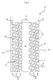
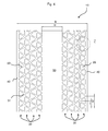
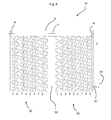
- FIGS. 2 to 5 show exemplary embodiments of inventive egg bands 10 in different widths B with different middle strips M without recesses.
- the egg bands 10 have recesses 20 which are arranged in rows 30, which extend in the conveying direction F.
- the recesses 20 of a row 30 are arranged so that in a series alternately rotated by 60 ° triangles are present, so that alternately in the conveying direction F right and left sides of the triangles 20 are aligned parallel to the conveying direction.
- the recesses 20 are formed as isosceles triangles and have a radius RA (FIG. Fig. 7 ) rounded corners.
- the triangle-shaped recesses 20 each circumscribe a circle with a diameter D in the in FIGS. 2 to 6 shown embodiments is 18.5 mm.
- the recesses 20 are arranged such that one side 20a is aligned parallel to the conveying direction F, another side 20b are aligned at an angle of 60 ° to the conveying direction F and the third side 20c at an angle of 120 ° to the conveying direction.
- the rows 30 are spaced apart from one another by webs 31 extending in the conveying direction F, the triangular-shaped recesses 20 are likewise separated from one another by webs 60.
- the webs 60 between the recesses 20 of a row 30 run alternately webs 60a with an orientation of 60 ° to the conveying direction F and webs 60b with an orientation of 120 ° to the conveying direction F.
- the webs 31, 60 preferably have a width S of 5 mm on.
- the two extending in the conveying direction edges 40 of the band are formed without recesses.
- the edges 40 have a width R of 10 mm.
- the width BR of a row 30 is preferably 24.75 millimeters.
- the conveyor belts 10 of FIGS. 2 to 6 each have a central, strip-shaped region 50, which extends in the conveying direction F, and is formed without recesses.
- the distance A1 is preferably 23.53 millimeters and the distance A2 is preferably 47.05 millimeters.
- Fig. 6 represents a construction scheme with which the concrete designs of the in the FIGS. 2 to 5 shown egg bands and other egg band widths can be determined.
- the following table shows the nominal width of the egg bands, which corresponds to the value X.
- the dimension Y denotes the width of the respective middle strip M.
- the figures refer to recesses 20, which circumscribe a circle with a diameter of 18.5 mm.
- For the various nominal widths of the egg bands it is indicated which of the left and right rows 30, designated from 1 to 9, are each made non-perforated in order to produce the corresponding egg bands.
- rows 30 of triangular holes have the respective egg band of the corresponding nominal width.
Landscapes
- Life Sciences & Earth Sciences (AREA)
- Birds (AREA)
- Environmental Sciences (AREA)
- Engineering & Computer Science (AREA)
- Mechanical Engineering (AREA)
- Biodiversity & Conservation Biology (AREA)
- Animal Husbandry (AREA)
- Zoology (AREA)
- Belt Conveyors (AREA)
- Packaging Frangible Articles (AREA)
- Housing For Livestock And Birds (AREA)
- Structure Of Belt Conveyors (AREA)
- Meat, Egg Or Seafood Products (AREA)
Abstract
Description
- Die Erfindung betrifft ein Eierband umfassend ein sich in einer Förderrichtung erstreckendes Band zum Fördern von Eiern in einer Förderrichtung und einer Vielzahl von Ausnehmungen.
- Eierbänder werden in der Eierproduktion zum Transport von Eiern in einer Förderrichtung eingesetzt, beispielsweise beim Transport von Legehennenkäfigen zu Verpackungsstationen. Eierbänder sind oft Endlosbänder, die eine Haupterstreckungsrichtung haben, die mit der Förderrichtung übereinstimmt. Parallel zur Haupterstreckungsrichtung oder Förderrichtung ist ein Eierband von zwei Kanten oder Rändern begrenzt, ebenso wie quer zur Haupterstreckungsrichtung oder Förderrichtung durch zwei Kanten oder Enden. Eierbänder können in verschiedenen Fördersystemen eingesetzt und durch verschiedene Mittel angetrieben werden, um Eier in der Förderrichtung zu transportieren.
- Neben Eiern gelangen oft auch Kotreste, Federn oder andere Verschmutzungen, wie beispielsweise Staub, auf das Band, lagern sich dort an und werden auf die Eier übertragen, so dass auch die Eier verschmutzt werden.
- Neben einer gewollten Bewegung der Eier zusammen mit dem Eierband in eine Förderrichtung findet oft auch eine Bewegung der Eier relativ zu dem Band statt, insbesondere Rollbewegungen vor oder zurück, d.h. in Förderrichtung oder entgegengesetzt, seitlich oder kombinierte Bewegungen hieraus. Solche Bewegungen der Eier relativ zum Band können zu Beschädigungen der Eier und zu verstärkter Schmutzübertragung vom Band auf die Eier führen und sind daher nicht gewünscht.
- Bei existierenden Eierbändern ist eine Vielzahl von Ausnehmungen im Band vorgesehen, wodurch zum einen Schutz durchfallen soll und zum anderen Rollbewegungen der Eier reduziert werden sollen. Ein Abschnitt eines bekannten Eierbands mit einer Vielzahl von kreisförmigen Ausnehmungen ist in
Figur 1 dargestellt. Ferner sind auch Eierbänder mit quadratischen Ausnehmungen bekannt. - Es ist eine Aufgabe der vorliegenden Erfindung, ein verbessertes Eierband bereitzustellen, insbesondere ein Eierband, bei dem die Eier weniger stark verschmutzt werden.
- Diese Aufgabe wird gelöst durch ein eingangs genanntes Eierband, das dadurch gekennzeichnet ist, dass die Ausnehmungen dreiecksförmig ausgebildet sind.
- Die erfindungsgemäße Ausgestaltung der Ausnehmungen als Dreiecke hat gegenüber dem im Stand der Technik bekannten Ausnehmungen der Eierbänder mehrere Vorteile.
- Ein erster Vorteil ist, dass bei der erfindungsgemäßen Ausbildung des Eierbands mit dreieckigen Ausnehmungen bzw. Löchern ein Ei mit einem Abschnitt seiner Oberfläche in eine solche dreiecksförmige Ausnehmung eintaucht und dabei an drei Punkten, also jeweils einem Punkt pro Dreiecksseite, durch das Band gelagert wird. Diese Dreipunktlagerung der Eier auf dem Eierband ist deutlich stabiler als bei einer Lagerung in kreisförmigen, quadratischen oder rechteckigen Ausnehmungen. Auf diese Weise kann mit dem erfindungsgemäßen Eierband eine Relativbewegung zwischen den Eiern und dem Band weiter reduziert werden.
- Insbesondere gegenüber runden Ausnehmungen haben die dreiecksförmigen Ausnehmungen der Erfindung den weiteren Vorteil, dass ringförmige Verschmutzungen an den Eiern vermieden werden können. Solche ringförmigen Verschmutzungen sind besonders auffällig und daher nachteilig. Durch die dreieckige Ausbildung der Ausnehmungen liegt ein Ei vorzugsweise unabhängig von seiner Ausrichtung immer nur mit drei Stellen auf dem Eierband auf, d. h. pro Seitenfläche einer dreiecksförmigen Ausnehmung gibt es eine Kontaktstelle mit dem Ei. Auf diese Weise entstehen nur punktförmige Verschmutzungsstellen anstelle von kreisrunden Verschmutzungsringen.
- Gegenüber bekannten Eierbändern mit quadratischen Ausnehmungen hat die Ausgestaltung mit dreieckigen Ausnehmungen ferner den Vorteil, dass eine höhere Stabilität des Eierbands gegeben ist, insbesondere bei Zugbelastungen des Eierbands in Förderrichtung und Scherbeanspruchungen in der Förderbandebene, die bei Zugbelastungen nicht parallel zur Förderrichtung sondern in einem Winkel hierzu auftreten. Bei Bändern mit quadratischen oder rechteckigen Ausnehmungen bzw. Löchern kann der Effekt auftreten, dass sich die Quadrate bzw. Rechtecke zu Parallelogrammen verziehen und dieser Verformung wenig Widerstand durch die Eierbandstruktur entgegengesetzt wird. Bei der erfindungsgemäßen Ausbildung der Ausnehmungen in Form von Dreiecken besteht gegenüber solchen Zug- und Scherbeanspruchungen eine deutlich höhere Stabilität.
- Mit dem erfindungsgemäßen Eierband kann die Verschmutzung der Eier somit deutlich reduziert werden, da gegenüber einer ringförmigen oder mindestens 4-Punkt-förmigen Lagerung des Eies bei der erfindungsgemäßen 3-Punkt-Lagerung nur eine minimale Anzahl an erforderlichen Kontaktpunkten zwischen dem Ei und dem Eierband besteht und somit die über die Kontaktstellen erfolgende Schmutzübertragung vom Eierband auf das Ei gegenüber existierenden Bändern reduziert ist. Ferner weist das erfindungsgemäße Eierband eine höhere Stabilität gegenüber Zug- und Scherbeanspruchungen auf.
- Insbesondere kann auch gegenüber einer Ausgestaltung mit runden Ausnehmungen bei erfindungsgemäßen Eierband ein höherer Lochanteil pro Bandabschnitt, d. h. eine minimierte Oberfläche, realisiert werden, so dass sich Schmutz oder Staub nur noch auf der restlichen bzw. minimierten Oberfläche ablagern kann und sich daher insgesamt auf einem erfindungsgemäßen Eierband weniger Schmutz befindet. Auch dies trägt zu einer geringeren Verschmutzung der Eier bei.
- Die Ausnehmungen bzw. Löcher in dem Band sind vorzugsweise in einem regelmäßigen Muster angeordnet. Auf diese Weise kann die Stabilität des Bandes weiter erhöht werden.
- Ferner ist es bevorzugt, dass die Ausnehmungen als gleichschenklige Dreiecke ausgebildet sind. Auch diese Fortbildungsform hat den Vorteil einer besonders hohen Stabilität des Eierbands und einer verbesserten Lagerung der Eier gegenüber bekannten Eierbändern.
- Insbesondere können die dreiecksförmigen Ausnehmungen abgerundete Ecken aufweisen. Dies hat den Vorteil, dass sich in den Ecken der Dreiecke weniger Schmutz absetzen kann und daher die Verschmutzung der Eier weiter reduziert werden kann.
- In einer besonders bevorzugten Ausführungsform umschreiben die dreiecksförmigen Ausnehmungen jeweils einen Kreis mit einem Durchmesser von 15 bis 25 mm insbesondere 20 mm.
- Bei einer solchen Ausgestaltung der Dreiecke kann erreicht werden, dass die Eier in den Ausnehmungen ähnlich tief einsinken wie in bekannten Eierbändern mit kreisförmigen Ausnehmungen, d. h. das Ei taucht ähnlich tief durch das Band durch wie bei herkömmlichen Eierbändern. Gleichzeitig ist jedoch eine dreiecksförmige Ausnehmung, die einen Kreis mit einem bestimmten Durchmesser umschreibt, größer als die entsprechende kreisförmige Ausnehmung mit dem gleichen Durchmesser. Durch diese größeren dreiecksförmigen Ausnehmungen kann somit auch mehr Schmutz hindurchfallen als durch die kleineren kreisförmigen Ausnehmungen. Auf diese Weise kann die Oberfläche gegenüber bekannten Eierbändern weiter reduziert werden, so dass sich weniger Schmutz und Staub auf dem Eierband anlagern kann und die Verschmutzung der Eier reduziert wird, während gleichzeitig sichergestellt ist, dass die Eier nicht zu tief durch das Band durchhängen.
- In der bevorzugten Ausführungsform ist die Größe der Dreiecke so gewählt, dass ein Ei unabhängig von seiner Orientierung jeweils nur an drei Stellen mit dem Eierband in Berührung kommt, insbesondere jeweils mit einer Stelle einer Seitenwand eines Dreiecks. Die Unabhängigkeit von der Ausrichtung des Eies ergibt sich dadurch, dass das Ei sowohl mit seinem oberen oder unteren Ende, den "Polen", als auch mit dem Bereich des größten Umfangs dazwischen, seinem "Äquator", so in bzw. auf einer Ausnehmung zu liegen kommt, dass drei Kontaktstellen zwischen Ei und Eierband entstehen.
- In einer weiteren Ausführungsform ist bevorzugt, dass jeweils eine Seite einer Ausnehmung parallel zur Förderrichtung ausgerichtet ist, wobei vorzugswese die jeweils anderen beiden Seiten einer Ausnehmung in einem Winkel von 60° bzw. 120° zur Förderrichtung ausgerichtet sind.
- Besonders bevorzugt ist ferner, dass die dreiecksförmigen Ausnehmungen in zwei oder mehreren, sich in Förderrichtung erstreckenden Reihen angeordnet sind. Auf diese Weise ergibt sich eine besonders vorteilhafte, gleichmäßige Anordnung der Dreiecke, mit der insbesondere Eierbänder unterschiedlicher Breite leicht zu herzustellen sind. Insbesondere ist dabei bevorzugt, dass ein Eierband eine Breite aufweist, die einem Vielfachen der Breite einer solchen Reihe entspricht, ggf. zuzüglich von einer oder zwei Randbreiten an den sich in Förderrichtung erstreckenden Kanten des Eierbands.
- Vorzugsweise sind die dreiecksförmigen Ausnehmungen einer Reihe abwechselnd um 60° gedreht angeordnet. Auf diese Weise sind vorzugsweise abwechselnd die in Förderrichtung rechten und linken Seiten der Dreiecke einer Reihe parallel zur Förderrichtung ausgerichtet. Auch diese Ausrichtung wirkt sich positiv auf die Stabilität des Eierbands aus.
- Ferner ist bevorzugt, dass die Reihen durch sich in Förderrichtung erstreckende Stege voneinander beabstandet sind, wobei die Stege vorzugsweise eine Breite von weniger als 10 Millimeter haben, insbesondere eine Breite von 5 Millimetern.
- Solche Stege zwischen den Reihen der Ausnehmungen ermöglichen, dass beispielsweise ein Eierband leicht durch einen Schnitt in Förderrichtung etwa in der Mitte eines solchen Steges zu trennen ist, um Eierbänder unterschiedlicher Breite zu erhalten oder die Breite eines Eierbands zu verringern. Wenn ein Eierband nicht geteilt oder abgeschnitten werden soll, ist eine besonders schmale Ausbildung der Stege, beispielsweise von 5 Millimetern bevorzugt, um die Eierbandoberfläche, auf der sich Schmutz und Staub ablagern kann, gering zu halten.
- Zudem ist es bevorzugt, dass die dreiecksförmigen Ausnehmungen, insbesondere die dreiecksförmigen Ausnehmungen einer Reihe, durch Stege voneinander getrennt sind, die zur Förderrichtung in einem Winkel von 60° oder 120° ausgerichtet sind, wobei die Stege vorzugsweise eine Breite von weniger als 10 Millimeter haben, insbesondere eine Breite von 5 Millimetern.
- Auch zwischen den dreiecksförmigen Ausnehmungen, insbesondere innerhalb einer Reihe, sind vorzugsweise Stege vorgesehen. Diese Stege sind vorzugsweise ebenfalls schmal, beispielsweise mit einer Breite von 5 Millimetern, um die Eierbandoberfläche minimiert zu halten und damit Verschmutzungsmöglichkeiten zu reduzieren. Insbesondere in Kombination mit einer der oben genannten Ausrichtungen der Ausnehmungen ist es bevorzugt, dass die Stege zur Förderrichtung einen Winkel von 60° oder 120° bilden. Durch die unterschiedliche Ausrichtung der Dreiecke ergibt sich somit ein Netz von Stegen, das vorzugsweise aus in Förderrichtung verlaufenden Stegen zwischen den Reihen der Ausnehmungen sowie in den Reihen durch abwechselnd mit einem Winkel von 60° oder einem Winkel von 120° zur Förderrichtung angeordneten Stegen gebildet ist. Durch ein solches bevorzugtes Netz von Stegen ergibt sich eine besonders hohe Stabilität des Eierbands gegenüber Zug- oder Scherbelastungen.
- Vorzugsweise weist das Eierband einen oder mehrere Bereiche ohne Ausnehmungen auf. Hierunter ist zu verstehen, dass neben den Stegen, die einzelne Ausnehmungen voneinander trennen, größere Bereiche des Bandes ohne Ausnehmungen ausgebildet sind.
- Bevorzugt ist beispielsweise, dass eine mittlerer, streifenförmiger Bereich, der sich in Förderrichtung erstreckt, ohne Ausnehmungen ausgebildet ist, wobei vorzugsweise der mittlere Bereich eine Breite aufweist, die der Breite von einer, zwei oder mehreren Reihen von Ausnehmungen entspricht.
- Insbesondere bei Eierbändern mit einer großen Breite, insbesondere mit einer Anzahl von drei oder mehr Reihen von Ausnehmungen, ist ein solcher Bereich ohne Ausnehmungen bevorzugt, um die Stabilität des Eierbands weiter zu erhöhen. Ein solcher Streifen ohne Ausnehmungen kann auch dazu verwendet werden, das Eierband in Förderrichtung zu zerteilen. Produktionstechnisch gesehen ist die Ausbildung des Streifens mit einer Breite von einer, zwei oder mehreren Reihen von Ausnehmungen vorteilhaft, da in der Produktion diese Reihen einfach ohne Ausnehmungen produziert werden können, die Breiten der Eierbänder jedoch im Wesentlichen gleich sind, unabhängig davon, ob mittlere Reihen mit oder ohne Ausnehmungen produziert werden.
- Ferner ist bevorzugt, dass einer oder beide der sich in Förderrichtung erstreckenden Ränder des Bandes ohne Ausnehmungen ausgebildet ist bzw. sind.
- Die Ausbildung eines durchgehenden Randes an einer sich in Förderrichtung erstreckenden Kante des Eierbands ist bevorzugt, beispielsweise zur Befestigung oder zum Antrieb des Bandes. Besonders bevorzugt ist die Ausbildung eines solchen Randes an beiden sich in Förderrichtung erstreckenden Kanten des Eierbands.
- Insbesondere ist dabei jedoch bevorzugt, dass der Rand bzw. die Ränder ohne Ausnehmungen eine Breite aufweist bzw. aufweisen, die kleiner ist als eine Seitenlänge einer dreiecksförmigen Ausnehmung.
- Insbesondere ist bevorzugt, dass der Rand bzw. die Ränder ohne Ausnehmungen eine Breite aufweist bzw. aufweisen, die kleiner ist als die Breite eines Streifens von Ausnehmungen, insbesondere kleiner als die Hälfte der Breite eines solchen Streifens. Ferner ist bevorzugt, dass der Rand bzw. die Ränder ohne Ausnehmungen eine Breite aufweist bzw. aufweisen, die kleiner ist als die Hälfte einer Länge einer Seite einer dreiecksfömigen Ausnehmung. Besonders ist bevorzugt, dass die Breite des Randes bzw. der Ränder kleiner ist als 15 Millimeter, besonders bevorzugt ist eine Breite von 10 Millimetern.
- In einer besonders bevorzugten Ausführungsform kann ein Eierband gefertigt werden, indem die Reihen mit dreiecksförmigen Ausnehmungen von einer sich in Förderrichtung erstreckenden Mittellinie aus so weit nach links und rechts angeordnet werden, dass sich rechts und links jeweils ein Rand ohne Ausnehmungen mit einer bestimmten Breite, insbesondere einer Breite von 10 Millimetern, ergibt. Dabei kann ein mittlerer, streifenförmiger, sich in Förderrichtung erstreckender Bereich ohne Ausnehmungen ergeben, dessen Breite sich ergibt ausgehend von der Gesamtbreite des Eierbands abzüglich der Breite der beiden Ränder und abzüglich der Breite der insgesamt rechts und links vorgesehenen Reihen mit Ausnehmungen.
- Eine solche schmale Ausbildung des Randbereichs bzw. der Randbereiche hat den Vorteil, dass ein quer zur Förderrichtung auf das Eierband, beispielsweise aus einem Käfig, rollendes Ei schnell eine der dreiecksförmigen Ausnehmungen erreicht und dadurch nur über die möglichst schmale Breite des Randbereichs mit dem Eierband in Berührung kommt. Weniger Kontakt mit dem Eierband resultiert vorteilhafter Weise in geringeren Verschmutzungen der Eier.
- Ferner hat ein schmaler Randbereich den Vorteil, dass beispielsweise aus den Käfigen auf das Eierband gelangende Verschmutzungen, wie beispielsweise Kot oder Federn, schnell den dreiecksförmigen Ausnehmungen zugeführt werden und durch diese Ausnehmungen durchfallen können, so dass insgesamt weniger Schmutz auf dem Eierband verbleibt.
- Vorzugsweise weist ferner mindestens ein Ende des Bandes eine Kante auf, die zur Förderrichtung einen Winkel von 60° oder 120° ausgerichtet ist.
- Üblicherweise werden Eierbänder getrennt durch einen Schnitt quer bzw. orthogonal zur Förderrichtung. Insbesondere in Kombination mit einer der oben genannten Ausrichtungen der dreieckigen Ausnehmungen ist jedoch bevorzugt, dass ein oder beide Enden des Bandes nicht einen Winkel von 90° zur Förderrichtung, sondern einen Winkel von 60° oder 120° zur Förderrichtung aufweisen. Dadurch kann erreicht werden, dass diese Kanten zumindest abschnittsweise im Bereich der vorzugsweise mit einem Winkel von 60° oder 120° zur Förderrichtung ausgerichteten Stege zwischen den Ausnehmungen verlaufen. Dies erleichtert die Handhabung der Enden des Eierbands, da diese dadurch kompakter ausgestaltet sind.
- Besonders bevorzugt ist, dass das Eierband Kunststoff, vorzugsweise ein Thermoplast, insbesondere Polypropylen, aufweist oder daraus besteht, und/oder im Extrusionsverfahren hergestellt ist.
- Das Eierband ist vorzugsweise aus einem flexiblen Material hergestellt. Besonders bevorzugt ist eine Dicke des Eierbandes von unter zwei Millimetern, insbesondere von 1,3 Millimetern oder weniger. Durch die erfindungsgemäße Ausgestaltung der Ausnehmungen als Dreiecke und ggf. weiterer Fortbildungen des Eierbandes wird die Stabilität des Eierbandes erhöht, so dass eine geringere Dicke erforderlich ist, wodurch Material und Gewicht eingespart werden können.
- Bevorzugte Ausführungsformen der Erfindung werden beispielhaft anhand der beiliegenden Figuren beschrieben. Es zeigen:
- Fig. 1:
- ein Eierband mit kreisrunden Ausnehmungen aus dem Stand der Technik;
- Fig. 2:
- eine erste Ausführungsform eines erfindungsgemäßen Eierbands;
- Fig. 3:
- eine zweite Ausführungsform eines erfindungsgemäßen Eierbands;
- Fig. 4:
- eine dritte Ausführungsform eines erfindungsgemäßen Eierbands;
- Fig. 5:
- eine vierte Ausführungsform eines erfindungsgemäßen Eierbands;
- Fig. 6:
- Aufbauschema für konkrete Ausgestaltungen erfindungsgemäßer Eierbänder; und
- Fig. 7:
- das Detail Z aus den
Figuren 2 bis 6 . -
Fig. 1 zeigt ein Eierband 1 mit kreisrunden Ausnehmungen 2 aus dem Stand der Technik. - Die
Figuren 2 bis 5 zeigen beispielhafte Ausführungsformen erfindungsgemäßer Eierbänder 10 in unterschiedlichen Breiten B mit unterschiedlichen mittleren Streifen M ohne Ausnehmungen. Die Eierbänder 10 weisen Ausnehmungen 20 auf, die in Reihen 30 angeordnet sind, die sich in Förderrichtung F erstrecken. Die Ausnehmungen 20 einer Reihe 30 sind dabei so angeordnet, dass in einer Reihe abwechselnd um 60° gedrehte Dreiecke vorhanden sind, sodass abwechselnd die in Förderrichtung F rechten und linken Seiten der Dreiecke 20 parallel zur Förderrichtung ausgerichtet sind. Die Ausnehmungen 20 sind als gleichschenklige Dreiecke ausgebildet und weisen mit einem Radius RA (Fig. 7 ) abgerundete Ecken auf. - Wie insbesondere in
Fig. 7 zu erkennen ist, umschreiben die dreiecksförmigen Ausnehmungen 20 jeweils einen Kreis mit einem Durchmesser D, der in den inFiguren 2 bis 6 gezeigten Ausführungsbeispielen 18,5 mm beträgt. Die Ausnehmungen 20 sind derart angeordnet, dass jeweils eine Seite 20a parallel zur Förderrichtung F ausgerichtet ist, eine weitere Seite 20b in einem Winkel von 60° zur Förderrichtung F und die dritte Seite 20c in einem Winkel von 120° zur Förderrichtung ausgerichtet sind. - Die Reihen 30 sind durch sich in Förderrichtung F erstreckende Stege 31 voneinander beabstandet, die dreiecksförmigen Ausnehmungen 20 sind ebenfalls durch Stege 60 voneinander getrennt. Von den Stegen 60 zwischen den Ausnehmungen 20 einer Reihe 30 verlaufen abwechselnd Stege 60a mit einer Ausrichtung von 60° zur Förderrichtung F und Stege 60b mit einer Ausrichtung von 120° zur Förderrichtung F. Die Stege 31, 60 weisen vorzugsweise eine Breite S von 5 mm auf.
- Die beiden sich in Förderrichtung erstreckenden Ränder 40 des Bandes sind ohne Ausnehmungen ausgebildet. Die Ränder 40 weisen eine Breite R von 10 mm auf. Die Breite BR einer Reihe 30 beträgt vorzugsweise 24,75 Millimeter.
- Die Förderbänder 10 der
Figuren 2 bis 6 weisen jeweils einen mittleren, streifenförmigen Bereich 50 auf, der sich in Förderrichtung F erstreckt, und ohne Ausnehmungen ausgebildet ist. - Die Gesamtbreiten B des Bandes 10, die Anzahl der Reihen 30 der Ausnehmungen 20 sowie die Breite des mittleren Streifens M der Eierbänder 10 variieren in den in den
Figuren 2 bis 5 dargestellten Beispielen wie folgt: - Fig. 2:
- Zweimal zwei Reihen 30, B = 196 mm, M = 67 mm,
- Fig. 3:
- Zweimal drei Reihen 30, B = 245 mm, M = 56,50 mm
- Fig. 4:
- Zweimal vier Reihen 30, B = 350 mm, M = 102 mm
- Fig. 5:
- Zweimal fünf Reihen 30, B = 400 mm, M = 92,50 mm
- In allen gezeigten Ausführungsformen beträgt der Abstand A1 vorzugsweise 23,53 Millimeter und der Abstand A2 vorzugsweise 47,05 Millimeter.
-
Fig. 6 stellt ein Aufbauschema dar, mit dem die konkreten Ausgestaltungen der in denFiguren 2 bis 5 dargestellten Eierbänder sowie weitere Eierbandbreiten bestimmt werden können. - In der folgenden Tabelle ist die Nennbreite der Eierbänder angegeben, die dem Wert X entspricht. Mit dem Maß Y ist die Breite des jeweils mittleren Streifens M bezeichnet. Die Angaben beziehen sich auf Ausnehmungen 20, die einen Kreis mit einem Durchmesser von 18,5 mm umschreiben. Für die verschiedenen Nennbreiten der Eierbänder ist angegeben, welche der mit von 1 bis 9 bezeichneten linken und rechten Reihen 30 jeweils als nicht gelocht ausgeführt werden, um die entsprechenden Eierbänder herzustellen. Ferner ist bei der Benennung angegeben, wie viele Reihen 30 von Dreieckslöchern das jeweilige Eierband der entsprechenden Nennbreite aufweist.
Benennung Maß X Maß Y nicht gelocht links nicht gelocht rechts Eierband 600 mm; 14 x Dreiecklock Dia 18,5mm 600 mm 54,5mm 4,5 4,5 Eierband 500 mm; 12 x Dreiecklock Dia 1,8mm 500 mm 73,5mm 3, 8, 9 3, 8, 9 Eierband 400 mm; 10 x Dreiecklock Dia 18,5mm 400 mm 92,5mm 6, 7, 8, 9 6, 7, 8, 9 Eierband 350 mm; 8 x Dreiecklock Dia 18,5mm 350 mm 102mm 5, 6, 7, 8, 9 5, 6, 7, 8, 9 Eierband 245 mm; 6 x Dreiecklock Dia 18,5mm 245 mm 56,5mm 4, 5, 6, 7, 8, 9 4, 5, 6, 7, 8, 9 Eierband 196 mm; 4 x Dreiecklock Dia 18,5mm 196 mm 67mm 3, 4, 5, 6, 7, 8, 9 3, 4, 5, 6, 7, 8, 9
Claims (15)
- Eierband umfassend ein sich in einer Förderrichtung erstreckendes Band zum Fördern von Eiern in einer Förderrichtung und einer Vielzahl von Ausnehmungen bzw. Löchern,
dadurch gekennzeichnet, dass die Ausnehmungen bzw. Löcher dreiecksförmig ausgebildet sind. - Eierband nach dem vorhergehenden Anspruch,
dadurch gekennzeichnet, dass die Ausnehmungen bzw. Löcher als gleichschenklige Dreiecke ausgebildet sind. - Eierband nach einem der beiden vorhergehenden Ansprüche,
dadurch gekennzeichnet, dass die dreiecksförmigen Ausnehmungen bzw. Löcher abgerundete Ecken aufweisen. - Eierband nach einem der vorhergehenden Ansprüche,
dadurch gekennzeichnet, dass die dreiecksförmigen Ausnehmungen bzw. Löcher jeweils einen Kreis mit einem Durchmesser von 15 bis 25 Millimeter, insbesondere 20 Millimeter, umschreiben. - Eierband nach einem der vorhergehenden Ansprüche,
dadurch gekennzeichnet, dass die dreiecksförmigen Ausnehmungen bzw. Löcher derart angeordnet sind, dass jeweils eine Seite einer Ausnehmung bzw. eines Lochs parallel zur Förderrichtung ausgerichtet ist, wobei vorzugswese die jeweils anderen beiden Seiten einer Ausnehmung bzw. eines Lochs in einem Winkel von 60° bzw. 120° zur Förderrichtung ausgerichtet sind. - Eierband nach einem der vorhergehenden Ansprüche,
dadurch gekennzeichnet, dass die dreiecksförmigen Ausnehmungen bzw. Löcher in zwei oder mehreren, sich in Förderrichtung erstreckenden Reihen angeordnet sind. - Eierband nach dem vorhergehenden Anspruch,
dadurch gekennzeichnet, dass die dreiecksförmigen Ausnehmungen bzw. Löcher einer Reihe abwechselnd um 60° gedreht angeordnet sind. - Eierband nach einem der beiden vorhergehenden Ansprüche,
dadurch gekennzeichnet, dass die Reihen durch sich in Förderrichtung erstreckende Stege voneinander beabstandet sind, wobei die Stege vorzugsweise eine Breite von weniger als 10 Millimeter haben, insbesondere eine Breite von 5 Millimetern. - Eierband nach einem der vorhergehenden Ansprüche,
dadurch gekennzeichnet, dass die dreiecksförmigen Ausnehmungen bzw. Löcher, insbesondere die dreiecksförmigen Ausnehmungen bzw. Löcher einer Reihe, durch Stege voneinander getrennt sind, die zur Förderrichtung in einem Winkel von 60° oder 120° ausgerichtet sind, wobei die Stege vorzugsweise eine Breite von weniger als 10 Millimeter haben, insbesondere eine Breite von 5 Millimetern. - Eierband nach einem der vorhergehenden Ansprüche,
dadurch gekennzeichnet, dass das Band einen oder mehrere Bereiche ohne Ausnehmungen bzw. Löcher aufweist. - Eierband nach dem vorhergehenden Anspruch,
dadurch gekennzeichnet, dass eine mittlerer, streifenförmiger Bereich, der sich in Förderrichtung erstreckt, ohne Ausnehmungen bzw. Löcher ausgebildet ist, wobei vorzugsweise
der mittlere Bereich eine Breite aufweist, die der Breite von einer, zwei oder mehreren Reihen von Ausnehmungen bzw. Löchern entspricht. - Eierband nach einem der beiden vorhergehenden Ansprüche,
dadurch gekennzeichnet, dass einer oder beide der sich in Förderrichtung erstreckenden Ränder des Bandes ohne Ausnehmungen bzw. Löcher ausgebildet ist bzw. sind. - Eierband nach dem vorhergehenden Anspruch,
dadurch gekennzeichnet, dass der Rand bzw. die Ränder ohne Ausnehmungen bzw. Löcher eine Breite aufweist bzw. aufweisen, die kleiner ist als eine Seitenlänge einer dreiecksförmigen Ausnehmung bzw. eines dreiecksförmigen Lochs, vorzugsweise beträgt die Breite 10 Millimeter. - Eierband nach einem der vorhergehenden Ansprüche,
dadurch gekennzeichnet, dass mindestens ein Ende des Bandes eine Kante aufweist, die zur Förderrichtung in einem Winkel von 60° oder 120° ausgerichtet ist. - Eierband nach einem der vorhergehenden Ansprüche,
dadurch gekennzeichnet, dass das Eierband Kunststoff, vorzugsweise ein Thermoplast, insbesondere Polypropylen, aufweist oder daraus besteht, und/oder im Extrusionsverfahren hergestellt ist.
Applications Claiming Priority (1)
| Application Number | Priority Date | Filing Date | Title |
|---|---|---|---|
| DE202012004330U DE202012004330U1 (de) | 2012-05-03 | 2012-05-03 | Eierband |
Publications (4)
| Publication Number | Publication Date |
|---|---|
| EP2674030A2 true EP2674030A2 (de) | 2013-12-18 |
| EP2674030A3 EP2674030A3 (de) | 2014-06-04 |
| EP2674030B1 EP2674030B1 (de) | 2024-03-06 |
| EP2674030C0 EP2674030C0 (de) | 2024-03-06 |
Family
ID=46510010
Family Applications (1)
| Application Number | Title | Priority Date | Filing Date |
|---|---|---|---|
| EP13164091.4A Active EP2674030B1 (de) | 2012-05-03 | 2013-04-17 | Eierband |
Country Status (8)
| Country | Link |
|---|---|
| US (1) | US8820519B2 (de) |
| EP (1) | EP2674030B1 (de) |
| CN (1) | CN103381950B (de) |
| BR (1) | BR102013011009B1 (de) |
| DE (1) | DE202012004330U1 (de) |
| EA (1) | EA024273B1 (de) |
| ES (1) | ES2987197T3 (de) |
| PL (1) | PL2674030T3 (de) |
Families Citing this family (7)
| Publication number | Priority date | Publication date | Assignee | Title |
|---|---|---|---|---|
| US10945874B2 (en) | 2012-05-15 | 2021-03-16 | Akervall Technologies, Inc. | Custom-formable night grinding appliance and method of use |
| EA028198B1 (ru) | 2012-10-24 | 2017-10-31 | Биг Дачман Интернэшнл Гмбх | Конвейер и способ транспортировки продуктов жизнедеятельности животных в сельскохозяйственном предприятии |
| DE202014007282U1 (de) | 2014-09-12 | 2015-12-16 | Big Dutchman International Gmbh | Dosiervorrichtung |
| CN104585071A (zh) * | 2015-01-05 | 2015-05-06 | 青岛平度市金巢机械有限责任公司 | 一种产蛋箱的种蛋输送装置 |
| DE202016105370U1 (de) | 2016-09-27 | 2018-01-02 | Big Dutchman International Gmbh | Fütterungsvorrichtung für Geflügeltiere |
| NL2021127B1 (en) * | 2018-06-15 | 2019-12-20 | Hatchtech Group Bv | Egg tray for supporting eggs in an incubation chamber |
| AU2024236302A1 (en) * | 2023-03-16 | 2025-08-21 | St Equipment & Technology Llc | Continuous belt for belt-type separator devices |
Family Cites Families (22)
| Publication number | Priority date | Publication date | Assignee | Title |
|---|---|---|---|---|
| DE7102326U (de) | 1971-09-30 | Farbwerke Hoechst Ag | Eiertransportband | |
| DE525996C (de) | 1931-06-01 | Otto Klaushenke | Eierfoerdervorrichtung | |
| DE603231C (de) * | 1933-08-03 | 1935-06-08 | Johannes Rudolph Surmann | Kisteneinsatz zur Aufnahme von Eiern |
| US2074383A (en) * | 1934-06-22 | 1937-03-23 | Globe Egg Stabilizing Company | Egg handling machine |
| US2096105A (en) * | 1936-01-31 | 1937-10-19 | Earl G Griffith | Conveyer |
| US2149686A (en) * | 1936-06-03 | 1939-03-07 | Frederick L Rivenburgh | Egg testing method and machine |
| GB647498A (en) * | 1947-09-12 | 1950-12-13 | Richard Douglas Scoble Hodgins | Improvements in or relating to apparatus for sorting apples, eggs or other suitable articles |
| DE1820785U (de) * | 1960-08-04 | 1960-10-27 | Vis Kunststoffwerk Alfred Hube | Transportband bzw. treibriemen mit reibbelag. |
| NL6502207A (de) * | 1964-03-10 | 1965-09-13 | ||
| SU506551A1 (ru) * | 1974-02-07 | 1976-03-15 | Всесоюзный Ордена Трудового Красного Знамени Научно-Исследовательский Институт Сельскохозяйственного Машиностроения Имени В.П.Горячкина | Устройство дл транспортировани иц |
| US3898435A (en) * | 1974-03-11 | 1975-08-05 | Fmc Corp | Memory device for an egg grading machine |
| JPS5818292B2 (ja) * | 1980-03-29 | 1983-04-12 | 友末 弘 | 鶏卵をその姿勢を揃えて立て並べる装置 |
| NL8202431A (nl) * | 1982-06-16 | 1984-01-16 | Meyn Pieter | Machine voor het verpakken van eieren. |
| US4860569A (en) * | 1988-05-02 | 1989-08-29 | Service Tool Die & Mfg. Company | Conveyor for conversion systems |
| US5232080A (en) * | 1989-03-10 | 1993-08-03 | Fps Food Processing Systems B.V. | Article handling method and apparatus |
| GB9025639D0 (en) * | 1990-11-26 | 1991-01-09 | Mckinlay Bruce A | Egg transporting and packing apparatus |
| FR2738638B1 (fr) * | 1995-09-13 | 1998-02-27 | Rangeard Patrick | Dispositif de mirage et calibrage |
| JP2001039410A (ja) * | 1999-05-24 | 2001-02-13 | Nambu Electric Co Ltd | 物品の選別包装装置 |
| KR100425930B1 (ko) * | 2002-01-16 | 2004-04-14 | 김진술 | 종란 자동 난상장치 |
| US6776278B1 (en) * | 2003-04-08 | 2004-08-17 | Embrex, Inc. | Egg transfer apparatus with converging guides that facilitate even distribution of eggs on a moving conveyor |
| NL1028582C2 (nl) * | 2005-03-21 | 2006-09-25 | A H Jansen Holding B V | Legnest voor pluimvee, en werkwijze voor het houden van pluimvee middels een dergelijk legnest. |
| CN201369990Y (zh) * | 2009-01-21 | 2009-12-30 | 李和富 | 一种自动集蛋设备及其系统 |
-
2012
- 2012-05-03 DE DE202012004330U patent/DE202012004330U1/de not_active Expired - Lifetime
-
2013
- 2013-04-17 EP EP13164091.4A patent/EP2674030B1/de active Active
- 2013-04-17 ES ES13164091T patent/ES2987197T3/es active Active
- 2013-04-17 PL PL13164091.4T patent/PL2674030T3/pl unknown
- 2013-04-30 EA EA201300433A patent/EA024273B1/ru unknown
- 2013-05-02 US US13/875,631 patent/US8820519B2/en active Active
- 2013-05-03 BR BR102013011009-4A patent/BR102013011009B1/pt not_active IP Right Cessation
- 2013-05-03 CN CN201310160690.2A patent/CN103381950B/zh not_active Expired - Fee Related
Non-Patent Citations (1)
| Title |
|---|
| None |
Also Published As
| Publication number | Publication date |
|---|---|
| DE202012004330U1 (de) | 2012-05-18 |
| BR102013011009B1 (pt) | 2019-11-12 |
| CN103381950B (zh) | 2016-08-17 |
| EP2674030A3 (de) | 2014-06-04 |
| EA201300433A1 (ru) | 2013-11-29 |
| BR102013011009A2 (pt) | 2015-06-30 |
| ES2987197T3 (es) | 2024-11-14 |
| EA024273B1 (ru) | 2016-09-30 |
| US8820519B2 (en) | 2014-09-02 |
| EP2674030B1 (de) | 2024-03-06 |
| US20130299317A1 (en) | 2013-11-14 |
| CN103381950A (zh) | 2013-11-06 |
| PL2674030T3 (pl) | 2024-08-05 |
| EP2674030C0 (de) | 2024-03-06 |
Similar Documents
| Publication | Publication Date | Title |
|---|---|---|
| EP2674030A2 (de) | Eierband | |
| DE69127289T2 (de) | Kunststoff-förderband mit integrierten seitenplatten | |
| DE2020108C3 (de) | Plattenband | |
| CH646902A5 (de) | Verfahren zur herstellung eines kunststoff-netzes mit rautenfoermigen maschen sowie nach dem verfahren hergestelltes netz. | |
| EP0074665B1 (de) | Bandförmiger Riemen für Maschinen zum Aufnehmen von Erntegut und Bilden von zylindrischen Ballen | |
| DE1934347A1 (de) | Foerderband | |
| DE3701772A1 (de) | Foerderbandkettenglied | |
| DE1810835B2 (de) | Endloses Förderband mit Zugliedern aus Flachdraht | |
| DE102008022282A1 (de) | Einrichtung und Verfahren zur Behandlung von Silizium-Wafern oder flachen Gegenständen | |
| DE69822715T2 (de) | Seitenführung für eine Speicherstation, mit einer Doppelreihe von Rollen | |
| DE2634934C3 (de) | Plattenartiges Siebelement | |
| EP0418640B1 (de) | Käfig für ein Wälzlager für Längsbewegungen | |
| DE7723785U1 (de) | Vorrichtung zum ausrichten von mit einem bindemittel versehenen, lignozellulosehaltigen teilchen | |
| DE69722749T2 (de) | Förderbandmodul sowie Förderband | |
| DE102015000983A1 (de) | Messerkopf für eine Produktschneidemaschine | |
| EP3095736B1 (de) | Förderstrecke mit einer anzahl von mit traversen gekoppelten bandunterstützungmodulen | |
| DE20116382U1 (de) | Transportband | |
| DE112006003327B4 (de) | Modulare Transportmatte und Transportmattenmodul | |
| DE102021127421A1 (de) | Transporteinrichtung | |
| AT402204B (de) | Teilungskamm | |
| DE3014294C2 (de) | Stacheldraht | |
| EP2167407B1 (de) | Kontinuierliches transportband | |
| DE2619128C3 (de) | Schuppenblech zur Herstellung einer rutschsicheren Fläche | |
| DE3011836C2 (de) | Gitterplatte zur Bildung von Plus- und Minus-Plattensätzen für Sammlerbatterien | |
| DE3340355A1 (de) | Radlastwaage |
Legal Events
| Date | Code | Title | Description |
|---|---|---|---|
| PUAI | Public reference made under article 153(3) epc to a published international application that has entered the european phase |
Free format text: ORIGINAL CODE: 0009012 |
|
| AK | Designated contracting states |
Kind code of ref document: A2 Designated state(s): AL AT BE BG CH CY CZ DE DK EE ES FI FR GB GR HR HU IE IS IT LI LT LU LV MC MK MT NL NO PL PT RO RS SE SI SK SM TR |
|
| AX | Request for extension of the european patent |
Extension state: BA ME |
|
| PUAL | Search report despatched |
Free format text: ORIGINAL CODE: 0009013 |
|
| AK | Designated contracting states |
Kind code of ref document: A3 Designated state(s): AL AT BE BG CH CY CZ DE DK EE ES FI FR GB GR HR HU IE IS IT LI LT LU LV MC MK MT NL NO PL PT RO RS SE SI SK SM TR |
|
| AX | Request for extension of the european patent |
Extension state: BA ME |
|
| RIC1 | Information provided on ipc code assigned before grant |
Ipc: A01K 31/16 20060101AFI20140429BHEP Ipc: B65G 15/58 20060101ALI20140429BHEP |
|
| 17P | Request for examination filed |
Effective date: 20140819 |
|
| RBV | Designated contracting states (corrected) |
Designated state(s): AL AT BE BG CH CY CZ DE DK EE ES FI FR GB GR HR HU IE IS IT LI LT LU LV MC MK MT NL NO PL PT RO RS SE SI SK SM TR |
|
| STAA | Information on the status of an ep patent application or granted ep patent |
Free format text: STATUS: EXAMINATION IS IN PROGRESS |
|
| 17Q | First examination report despatched |
Effective date: 20170829 |
|
| GRAP | Despatch of communication of intention to grant a patent |
Free format text: ORIGINAL CODE: EPIDOSNIGR1 |
|
| STAA | Information on the status of an ep patent application or granted ep patent |
Free format text: STATUS: GRANT OF PATENT IS INTENDED |
|
| INTG | Intention to grant announced |
Effective date: 20231109 |
|
| RIN1 | Information on inventor provided before grant (corrected) |
Inventor name: MOELLER, GUENTER |
|
| GRAS | Grant fee paid |
Free format text: ORIGINAL CODE: EPIDOSNIGR3 |
|
| GRAA | (expected) grant |
Free format text: ORIGINAL CODE: 0009210 |
|
| STAA | Information on the status of an ep patent application or granted ep patent |
Free format text: STATUS: THE PATENT HAS BEEN GRANTED |
|
| AK | Designated contracting states |
Kind code of ref document: B1 Designated state(s): AL AT BE BG CH CY CZ DE DK EE ES FI FR GB GR HR HU IE IS IT LI LT LU LV MC MK MT NL NO PL PT RO RS SE SI SK SM TR |
|
| REG | Reference to a national code |
Ref country code: GB Ref legal event code: FG4D Free format text: NOT ENGLISH |
|
| REG | Reference to a national code |
Ref country code: CH Ref legal event code: EP |
|
| REG | Reference to a national code |
Ref country code: IE Ref legal event code: FG4D Free format text: LANGUAGE OF EP DOCUMENT: GERMAN |
|
| REG | Reference to a national code |
Ref country code: DE Ref legal event code: R096 Ref document number: 502013016500 Country of ref document: DE |
|
| U01 | Request for unitary effect filed |
Effective date: 20240306 |
|
| U07 | Unitary effect registered |
Designated state(s): AT BE BG DE DK EE FI FR IT LT LU LV MT NL PT SE SI Effective date: 20240312 |
|
| U20 | Renewal fee for the european patent with unitary effect paid |
Year of fee payment: 12 Effective date: 20240320 |
|
| PGFP | Annual fee paid to national office [announced via postgrant information from national office to epo] |
Ref country code: GB Payment date: 20240429 Year of fee payment: 12 |
|
| PG25 | Lapsed in a contracting state [announced via postgrant information from national office to epo] |
Ref country code: GR Free format text: LAPSE BECAUSE OF FAILURE TO SUBMIT A TRANSLATION OF THE DESCRIPTION OR TO PAY THE FEE WITHIN THE PRESCRIBED TIME-LIMIT Effective date: 20240607 |
|
| PG25 | Lapsed in a contracting state [announced via postgrant information from national office to epo] |
Ref country code: HR Free format text: LAPSE BECAUSE OF FAILURE TO SUBMIT A TRANSLATION OF THE DESCRIPTION OR TO PAY THE FEE WITHIN THE PRESCRIBED TIME-LIMIT Effective date: 20240306 Ref country code: RS Free format text: LAPSE BECAUSE OF FAILURE TO SUBMIT A TRANSLATION OF THE DESCRIPTION OR TO PAY THE FEE WITHIN THE PRESCRIBED TIME-LIMIT Effective date: 20240606 |
|
| PGFP | Annual fee paid to national office [announced via postgrant information from national office to epo] |
Ref country code: ES Payment date: 20240529 Year of fee payment: 12 |
|
| PG25 | Lapsed in a contracting state [announced via postgrant information from national office to epo] |
Ref country code: RS Free format text: LAPSE BECAUSE OF FAILURE TO SUBMIT A TRANSLATION OF THE DESCRIPTION OR TO PAY THE FEE WITHIN THE PRESCRIBED TIME-LIMIT Effective date: 20240606 Ref country code: NO Free format text: LAPSE BECAUSE OF FAILURE TO SUBMIT A TRANSLATION OF THE DESCRIPTION OR TO PAY THE FEE WITHIN THE PRESCRIBED TIME-LIMIT Effective date: 20240606 Ref country code: HR Free format text: LAPSE BECAUSE OF FAILURE TO SUBMIT A TRANSLATION OF THE DESCRIPTION OR TO PAY THE FEE WITHIN THE PRESCRIBED TIME-LIMIT Effective date: 20240306 Ref country code: GR Free format text: LAPSE BECAUSE OF FAILURE TO SUBMIT A TRANSLATION OF THE DESCRIPTION OR TO PAY THE FEE WITHIN THE PRESCRIBED TIME-LIMIT Effective date: 20240607 |
|
| PGFP | Annual fee paid to national office [announced via postgrant information from national office to epo] |
Ref country code: TR Payment date: 20240528 Year of fee payment: 12 |
|
| PG25 | Lapsed in a contracting state [announced via postgrant information from national office to epo] |
Ref country code: IS Free format text: LAPSE BECAUSE OF FAILURE TO SUBMIT A TRANSLATION OF THE DESCRIPTION OR TO PAY THE FEE WITHIN THE PRESCRIBED TIME-LIMIT Effective date: 20240706 |
|
| PG25 | Lapsed in a contracting state [announced via postgrant information from national office to epo] |
Ref country code: SM Free format text: LAPSE BECAUSE OF FAILURE TO SUBMIT A TRANSLATION OF THE DESCRIPTION OR TO PAY THE FEE WITHIN THE PRESCRIBED TIME-LIMIT Effective date: 20240306 |
|
| PG25 | Lapsed in a contracting state [announced via postgrant information from national office to epo] |
Ref country code: CZ Free format text: LAPSE BECAUSE OF FAILURE TO SUBMIT A TRANSLATION OF THE DESCRIPTION OR TO PAY THE FEE WITHIN THE PRESCRIBED TIME-LIMIT Effective date: 20240306 |
|
| PGFP | Annual fee paid to national office [announced via postgrant information from national office to epo] |
Ref country code: PL Payment date: 20240322 Year of fee payment: 12 |
|
| PG25 | Lapsed in a contracting state [announced via postgrant information from national office to epo] |
Ref country code: SK Free format text: LAPSE BECAUSE OF FAILURE TO SUBMIT A TRANSLATION OF THE DESCRIPTION OR TO PAY THE FEE WITHIN THE PRESCRIBED TIME-LIMIT Effective date: 20240306 |
|
| PG25 | Lapsed in a contracting state [announced via postgrant information from national office to epo] |
Ref country code: SM Free format text: LAPSE BECAUSE OF FAILURE TO SUBMIT A TRANSLATION OF THE DESCRIPTION OR TO PAY THE FEE WITHIN THE PRESCRIBED TIME-LIMIT Effective date: 20240306 Ref country code: SK Free format text: LAPSE BECAUSE OF FAILURE TO SUBMIT A TRANSLATION OF THE DESCRIPTION OR TO PAY THE FEE WITHIN THE PRESCRIBED TIME-LIMIT Effective date: 20240306 Ref country code: RO Free format text: LAPSE BECAUSE OF FAILURE TO SUBMIT A TRANSLATION OF THE DESCRIPTION OR TO PAY THE FEE WITHIN THE PRESCRIBED TIME-LIMIT Effective date: 20240306 Ref country code: IS Free format text: LAPSE BECAUSE OF FAILURE TO SUBMIT A TRANSLATION OF THE DESCRIPTION OR TO PAY THE FEE WITHIN THE PRESCRIBED TIME-LIMIT Effective date: 20240706 Ref country code: CZ Free format text: LAPSE BECAUSE OF FAILURE TO SUBMIT A TRANSLATION OF THE DESCRIPTION OR TO PAY THE FEE WITHIN THE PRESCRIBED TIME-LIMIT Effective date: 20240306 |
|
| REG | Reference to a national code |
Ref country code: ES Ref legal event code: FG2A Ref document number: 2987197 Country of ref document: ES Kind code of ref document: T3 Effective date: 20241114 |
|
| REG | Reference to a national code |
Ref country code: CH Ref legal event code: PL |
|
| REG | Reference to a national code |
Ref country code: DE Ref legal event code: R097 Ref document number: 502013016500 Country of ref document: DE |
|
| PG25 | Lapsed in a contracting state [announced via postgrant information from national office to epo] |
Ref country code: MC Free format text: LAPSE BECAUSE OF FAILURE TO SUBMIT A TRANSLATION OF THE DESCRIPTION OR TO PAY THE FEE WITHIN THE PRESCRIBED TIME-LIMIT Effective date: 20240306 |
|
| PLBE | No opposition filed within time limit |
Free format text: ORIGINAL CODE: 0009261 |
|
| STAA | Information on the status of an ep patent application or granted ep patent |
Free format text: STATUS: NO OPPOSITION FILED WITHIN TIME LIMIT |
|
| PG25 | Lapsed in a contracting state [announced via postgrant information from national office to epo] |
Ref country code: MC Free format text: LAPSE BECAUSE OF FAILURE TO SUBMIT A TRANSLATION OF THE DESCRIPTION OR TO PAY THE FEE WITHIN THE PRESCRIBED TIME-LIMIT Effective date: 20240306 Ref country code: CH Free format text: LAPSE BECAUSE OF NON-PAYMENT OF DUE FEES Effective date: 20240430 |
|
| 26N | No opposition filed |
Effective date: 20241209 |
|
| PG25 | Lapsed in a contracting state [announced via postgrant information from national office to epo] |
Ref country code: IE Free format text: LAPSE BECAUSE OF NON-PAYMENT OF DUE FEES Effective date: 20240417 |
|
| PG25 | Lapsed in a contracting state [announced via postgrant information from national office to epo] |
Ref country code: CY Free format text: LAPSE BECAUSE OF FAILURE TO SUBMIT A TRANSLATION OF THE DESCRIPTION OR TO PAY THE FEE WITHIN THE PRESCRIBED TIME-LIMIT; INVALID AB INITIO Effective date: 20130417 |
|
| PG25 | Lapsed in a contracting state [announced via postgrant information from national office to epo] |
Ref country code: HU Free format text: LAPSE BECAUSE OF FAILURE TO SUBMIT A TRANSLATION OF THE DESCRIPTION OR TO PAY THE FEE WITHIN THE PRESCRIBED TIME-LIMIT; INVALID AB INITIO Effective date: 20130417 |
|
| U90 | Renewal fees not paid: noting of loss of rights |
Free format text: RENEWAL FEE NOT PAID FOR YEAR 13 Effective date: 20251114 |
|
| GBPC | Gb: european patent ceased through non-payment of renewal fee |
Effective date: 20250417 |
|
| PG25 | Lapsed in a contracting state [announced via postgrant information from national office to epo] |
Ref country code: GB Free format text: LAPSE BECAUSE OF NON-PAYMENT OF DUE FEES Effective date: 20250417 |
|
| U93 | Unitary patent lapsed |
Free format text: RENEWAL FEE NOT PAID Effective date: 20250430 |