EP2674247A2 - Appareil et procédé de commande d'entraînements d'une machine outil - Google Patents
Appareil et procédé de commande d'entraînements d'une machine outil Download PDFInfo
- Publication number
- EP2674247A2 EP2674247A2 EP13001731.2A EP13001731A EP2674247A2 EP 2674247 A2 EP2674247 A2 EP 2674247A2 EP 13001731 A EP13001731 A EP 13001731A EP 2674247 A2 EP2674247 A2 EP 2674247A2
- Authority
- EP
- European Patent Office
- Prior art keywords
- machine
- drive
- acceleration
- control device
- drives
- Prior art date
- Legal status (The legal status is an assumption and is not a legal conclusion. Google has not performed a legal analysis and makes no representation as to the accuracy of the status listed.)
- Withdrawn
Links
Images




Classifications
-
- G—PHYSICS
- G05—CONTROLLING; REGULATING
- G05B—CONTROL OR REGULATING SYSTEMS IN GENERAL; FUNCTIONAL ELEMENTS OF SUCH SYSTEMS; MONITORING OR TESTING ARRANGEMENTS FOR SUCH SYSTEMS OR ELEMENTS
- G05B19/00—Program-control systems
- G05B19/02—Program-control systems electric
- G05B19/18—Numerical control [NC], i.e. automatically operating machines, in particular machine tools, e.g. in a manufacturing environment, so as to execute positioning, movement or co-ordinated operations by means of program data in numerical form
- G05B19/416—Numerical control [NC], i.e. automatically operating machines, in particular machine tools, e.g. in a manufacturing environment, so as to execute positioning, movement or co-ordinated operations by means of program data in numerical form characterised by control of velocity, acceleration or deceleration
-
- G—PHYSICS
- G05—CONTROLLING; REGULATING
- G05B—CONTROL OR REGULATING SYSTEMS IN GENERAL; FUNCTIONAL ELEMENTS OF SUCH SYSTEMS; MONITORING OR TESTING ARRANGEMENTS FOR SUCH SYSTEMS OR ELEMENTS
- G05B2219/00—Program-control systems
- G05B2219/30—Nc systems
- G05B2219/34—Director, elements to supervisory
- G05B2219/34314—Slow down, limit speed for energy saving
-
- Y—GENERAL TAGGING OF NEW TECHNOLOGICAL DEVELOPMENTS; GENERAL TAGGING OF CROSS-SECTIONAL TECHNOLOGIES SPANNING OVER SEVERAL SECTIONS OF THE IPC; TECHNICAL SUBJECTS COVERED BY FORMER USPC CROSS-REFERENCE ART COLLECTIONS [XRACs] AND DIGESTS
- Y02—TECHNOLOGIES OR APPLICATIONS FOR MITIGATION OR ADAPTATION AGAINST CLIMATE CHANGE
- Y02P—CLIMATE CHANGE MITIGATION TECHNOLOGIES IN THE PRODUCTION OR PROCESSING OF GOODS
- Y02P90/00—Enabling technologies with a potential contribution to greenhouse gas [GHG] emissions mitigation
- Y02P90/02—Total factory control, e.g. smart factories, flexible manufacturing systems [FMS] or integrated manufacturing systems [IMS]
Definitions
- the present invention relates to a method for controlling a machine and a machine, which has at least one first drive for a first element of the machine and at least one second drive for a second element of the machine, which is different from the first drive.
- the energy costs increase if individual high power peaks accumulate within a range, for example, if a plurality of machines simultaneously have power peaks, e.g. by switching on the machines, since these power peaks must be covered by energy from control power plants, the energy price for this peak energy compared to the commonly used band energy is relatively expensive.
- the conventional machines require very high power peaks for a short time or generate again high regenerative powers for a short time, whereby the machine operators are required to maintain higher connection performance, especially if larger machinery is available, as is the case, for example, in the automotive industry.
- This staggered switching on and off of the drives is controlled by an S PS, which causes the startup, as well as the braking of one of the drives within the machine and possibly also the ancillaries delayed in time to another drive of the machine, so that, for example, a Spindle is accelerated to its predetermined rotational movement or speed only when the feed axes of the machine have already reached their target position or shortly after the feed axes have begun their movement towards their final position.
- S PS causes the startup, as well as the braking of one of the drives within the machine and possibly also the ancillaries delayed in time to another drive of the machine, so that, for example, a Spindle is accelerated to its predetermined rotational movement or speed only when the feed axes of the machine have already reached their target position or shortly after the feed axes have begun their movement towards their final position.
- this difference in coordination applies not only when starting or turning on the drives, but also when braking or switching off the drives, for example, a machining step when the feed axis must go back to the tool changer to receive a new tool and the spindle accordingly the rotational movement or Can reduce speed.
- the object of the present invention is to avoid power peaks when operating machines in order to reduce energy costs.
- This object is achieved by the present invention by means of a method for controlling machines and by means of a machine which has at least one first drive for a first element of the machine and at least one second drive for a second element of the machine different from the first drive, wherein the first element is accelerated to a predetermined target value and preferably a predetermined speed, while the second element is accelerated (or moved) to a predetermined target value, wherein the acceleration of the first element and the acceleration (or movement) of the second element (or this Elements associated with drives) are coordinated.
- the first target value and the second target value preferably differ from one another. In particular, these may be different mechanical variables and, in particular, different mechanical motion variables.
- the said target value is a value selected from a group including at least the position, the speed, the torque, the acceleration and the current. Consequently, the target value is, for example, the specification for achieving a specific speed, a specific rotational speed, a specific acceleration, a specific torque, a specific position or, in particular, motion sequences or combinations thereof or the like.
- the two drives are preferably independently controllable, but preferably the movements of the drives at least temporarily correlate with each other.
- the machine according to the invention listed is preferably a machine tool or a packaging or printing machine which, in addition to a drive for, for example, a spindle which carries out a rotational movement, also has at least one further drive for preferably a feed axis, which performs a translatory movement. having.
- said machine can also have only two or more drives, which only perform a rotary or only a translatory movement, these drives and the movements performed by the drives must be coordinated with each other at least temporarily.
- a spindle in this case is a machine element, such as a tool spindle to understand, which performs a rotational rotational movement about a centrally located spindle axis and thus also arranged on the spindle workpiece or tool in rotation.
- spindles are used for example in lathes during machining.
- feed axes are to be understood as meaning, in particular, programmable axes which determine a path in a defined space.
- a feed axis is found, for example, in lathes, wherein a tool is usually arranged on this element, which at least temporarily process the workpiece rotating about its own axis.
- the method according to the invention or the machine according to the invention can be used in all areas in which controlled drives for elements and corresponding ancillary units necessary for operating the machine should be operated in an energy-efficient manner so as not to exceed a maximum permissible power limit.
- the invention could also be used in printing presses or other automation devices.
- the machine further advantageously has at least one control device for controlling the drives arranged in the machine, wherein either a rotational speed or a rotational movement of the first drive of the first element is at least temporarily accelerated or a movement of the second drive of the second element is at least temporarily accelerated, so that the first element reaches its predetermined speed substantially at the same time as the second element reaches its predetermined target value.
- the control of the drives is preferably carried out via an NC controller, a motion controller, a PLC controller and / or an RC controller.
- the first element in this case is preferably a spindle, which must reach a predetermined (possibly also maximum) speed before the workpiece machining, while the second element is preferably a feed axis, which at the time the spindle reaches its predetermined speed has a predetermined processing position must have taken. At this predetermined speed, it is thus advantageous to set a target speed, which is specified for a specific operation or operating state of the machine.
- a feed axis is, for example, a linear or rotary axis operated in position control.
- the control device which is also referred to below as a power / energy consumption control device, performs at least a time requirement calculation or measurement of these drives before the accelerations of the drives, i. it is calculated or measured how long the individual drives need to accelerate the corresponding elements to a predetermined target value.
- a time requirement calculation or measurement of these drives before the accelerations of the drives, i. it is calculated or measured how long the individual drives need to accelerate the corresponding elements to a predetermined target value.
- the time required to reach the predetermined speed of the first element i. the time required for spindle run-up and the time required to reach the predetermined target value of the second element, i. the time required for the feed axis positioning movement is calculated.
- These at least two calculated time requirements are then compared with one another, for example by the power / energy consumption control device, in order to determine the higher or the greatest time requirement, which determines the predetermined or necessary time.
- the acceleration of the second drive so for example the drive of the feed axis is adapted to the acceleration of the first drive that the feed axis or the feed axes are moved at a lower or slower speed to the predetermined processing position. Accordingly, the feed axes are accelerated either slower positive or accelerated negatively, which Braking or delaying the movement of the feed axes in the direction of the predetermined position corresponds.
- An acceleration can thus have a positive or a negative value (delay). In all cases, it must be taken into account that the maximum permissible acceleration as well as the maximum permissible speed or speed or the maximum torque or the maximum current etc. is not exceeded.
- the time requirement determination of the power / energy consumption control device calculates that the feed axis for its movement to its defined target value, ie for their path covered, which may also be a plurality of consecutive translational or rotational movements in the different planes or directions according to the Cartesian coordinate system, requires a longer time.
- the acceleration of the spindle rotation of the acceleration of the feed motion of the feed axis is adjusted so that the drive of the spindle or the spindle is accelerated either with a lower positive acceleration to the predetermined speed or is braked with a lower negative acceleration, not to before the achievement of the feed axes at their target value to obtain their predetermined and possibly also maximum speed.
- the power / energy control device can also limit power peaks across one or more machines (with drives and accessories) as needed, as well as ensuring minimized machine performance at any one time across one or more machines.
- the changes in spindle and / or feed override i. changing the amount of energy available to the drives by adjusting, for example, an external power supply switch during the accelerations of the drives on the individual movements of the drives and should therefore be avoided, since an energy-efficient control of the drives already by the power / energy consumption control device itself is controlled and regulated.
- the power / energy consumption control device advantageously at least temporarily calls power used by the drives of the elements either via the power meter, which is arranged in or on the machine, or indirectly, in particular via models, using a plurality of control and / or status signals (at a Hydraulic unit, for example: hydraulic unit on, clamping to, clamping on, hydraulic unit running, ...), which indicate the currently present status of the individual elements or the individual drives of the elements of the machine, from individual arranged in or on the machine ancillaries to check whether the drives have an energy requirement which is still below the maximum permissible power limit or to determine whether the energy demand of the drives of the machine increases or is continuously within a possibly defined range.
- a Hydraulic unit for example: hydraulic unit on, clamping to, clamping on, hydraulic unit running
- the machine can have a multiplicity of sensor devices which measure the rotational speed, the position, the torque, and / or the electrically supplied or mechanically dissipated power / energy of the drives, the drives advantageously having servomotors which, for example, use a so-called servo drive Servo drive form.
- the control of the motors can be done on the basis of measurements of these sensor devices.
- this can be controlled in such a way that the drives are controlled accordingly energy-efficient.
- the power / energy consumption control device recognizes the at least temporarily necessary to control the machine ancillaries and controls them as needed, including the ancillaries or ancillary elements, such as a hydraulic unit or a cooling unit during their startup, their operation and of their shutdown use energy that can be attributed to the total energy consumption of the machine.
- the ancillaries or ancillary elements such as a hydraulic unit or a cooling unit during their startup, their operation and of their shutdown use energy that can be attributed to the total energy consumption of the machine.
- the power / energy consumption control device recognizes, stores and monitors substantially all information regarding a maximum permissible total output of the machine, summing up the energy consumption of all the aggregates and all auxiliary devices of the machine used and with a predetermined maximum permissible total output of the machine is adjusted to avoid exceeding the maximum permissible total power and corresponding power peaks and increased energy costs.
- the power / energy consumption control device for example, the acceleration of the movement of the first element, such as a spindle, and / or the acceleration of the movement of the second element, for example a feed axis, at least temporarily change, in particular reduce, if the permissible Overall performance of the machine is exceeded.
- the power / energy consumption control device in addition to or in addition to the change in the accelerations of the drives or instead of changing the accelerations of the drives, as described above, individual or even all the auxiliary equipment used for the use of the machine and the drives at least temporarily turns off.
- the power / energy consumption control device of the machine according to the invention has, for example, a so-called shutdown priority, which gives the power / energy consumption control device the possibility to individually switch off the individual drives of the elements and ancillaries even during startup of the machine or to switch them on slightly delayed.
- the selection of the ancillary units to be switched off hits the power / energy consumption control device, for example via defined machine parameters, which specify or specify in detail to the control device which ancillary units are absolutely required during certain processing steps or which minimum requirements, such as a minimum hydraulic pressure must be met and which are not necessary and in the meantime (at least for a short time) can be switched off until their use is needed again.
- the power / energy consumption control device can advantageously switch on and off individual ancillary units as required and necessary if the maximum permissible total output of the machine is exceeded due to the extensive parameters available to it and the present control and status signals.
- the power / energy controller could also limit power peaks across multiple machines (with drives and ancillaries) when needed. Accordingly, the energy consumption across several machines could be minimized.
- a machine in particular for machining workpieces, which has at least one first drive for a first element of the machine and at least one second drive for the second element of the machine different from the first drive, the machine having a power / energy consumption control device, which controls the drives of the elements of the machine such that the first drive accelerates the first element to a predetermined speed and the second drive accelerates the second element to a predetermined target value, the acceleration of the first element and the acceleration of the second element are coordinated.
- the first element of the machine according to the invention is a spindle and the second element is a feed axis.
- a control device may be provided which has a software program which has an algorithm for measuring the time required for the drives of the machine, wherein first the time requirement of the spindle run-up is calculated and then the time required for the feed axis positioning movement to derive the greatest amount of time by means of a comparison of the two determined time requirements among themselves. The greatest amount of time thus determines the predetermined time required to reach a predetermined target value and then all drives of the machine according to the invention can be aligned.
- the faster drives ie, the spindles and / or axes are slowed down with the lower time required to E reach the predetermined target value accordingly, for example, accordingly advantageous Feed axes are moved at a slower speed, while the spindles advantageously accelerated slower or even braked.
- the above-mentioned target value may be, for example, a target position, a target acceleration, a target speed, a target speed, a target torque, or a target current.
- the drives of the machine according to the invention are also advantageously adapted to one another again. For this purpose, if necessary, a new time requirement measurement is used.
- Fig. 1 shows a schematic diagram of an embodiment of a machine according to the invention, a control device 4 for controlling the drives 2a, 2b of the elements 3a, 3b, means for providing energy (not shown here, as arranged on the back of the machine) for the drives 2a , 2b of the elements 3a, 3b and a tool changing device 5. Furthermore, the machine 1 at least one auxiliary unit 6 and 7, which is for example a hydraulic unit.
- a spindle is provided as a first element 3a and at least one feed axis as a second element 3b.
- Fig. 2 are in the diagrams 8, 9 and 10, the accelerations, speeds or movements of the first drive 2a of the first element 3a and the second drive 2b of the second element 3b of the inventive machine 1 (see Fig.1 ), from the aspect that the first drive 2a has a higher time requirement than the second drive 2b. This time requirement is determined by means of the timepiece.
- the diagram 8 shows the spindle speed of the spindle and the diagram 9 the path velocity of the feed axis, whereby it becomes clear that the feed axis has already reached its predetermined position halfway through the time of the NC block. This means that the feed axis has already reached its target value while the spindle is still in its acceleration phase to reach a given speed. This situation becomes clear in the diagram 10.
- the feed axes could be moved at a lower acceleration or lower speed without clock time loss, and thus the power / energy consumption control means adapts the acceleration of the feed axes to the acceleration of the spindle.
- Fig. 3 the adaptation of the web speed is shown in diagram 12, whereby this adaptation takes place according to the time requirement of the spindle.
- the spindle requires a time t2 until it has reached its predetermined target value, ie a maximum speed which may have been necessary and predetermined for processing.
- the power / energy control device controls the drive of the feed axis, the drive, as in Fig. 2 described, for example, negatively accelerated, that is braked so as not to reach the target value, ie the predetermined position already at a time t1 as before the tuning of the drives (see curve 12a), but only, as well as the spindle at a time t2 ( see curve 12b).
- both elements reach their predetermined target value at the same time.
- the diagram 13 of Fig. 3 shows therefore the acceleration curve of the feed axis during a first not yet adapted to the spindle acceleration movement (curve 13a) and during an already adapted to the spindle acceleration acceleration (curve 13b), from which it can be clearly seen that at curve 13a, the acceleration of the feed axis already a has reached maximum value, although this is not necessary, since the spindle according to diagram 11 is still in an acceleration phase, then the feed axis must be braked again, and consequently already at a time t1 has reached the predetermined target value, then reaching the To have to wait for the target value of the spindle (or the feed axis).
- diagram 13 reveals increased energy expenditure, with eventual power peaks during the course of FIG. 13a, due to a tremendous positive acceleration and a subsequent negative acceleration, ie, deceleration, although the feed axes have nevertheless reached their target well ahead of the spindle.
- the feed axis is brought to a substantially mean acceleration and extends over a defined period of time with an acceleration which is relatively constant relative to the curve 13a until a defined time from which the acceleration is decelerated, which may correspond to an expiry of the acceleration.
- the feed axis preferably experiences a low positive and accordingly also a small negative acceleration until it reaches its target value, which preferably takes place from the feed axis simultaneously with the achievement of the target value of the spindle.
- a high energy consumption and possible power peaks is avoided without losses of the cycle time, which is specified by the drive or the element which has the greatest time requirement in the time requirement determination.
- first drives or spindle drives it would also be possible for a plurality of first drives or spindle drives to be adapted to the movement of the feed axis.
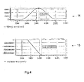
- the Fig. 4 shows in the diagram 14, the path velocity of the feed axis and in the diagram 15, the spindle speed of the spindle, which is clear that the feed axes have completed only half of the movement, while at the same time the spindle has already reached its predetermined speed.
- the power / energy consumption control means reduces the acceleration of the spindle so that both elements reach their predetermined target at the same time.
- FIG. 5 illustrates, in which the diagram 16 illustrates that the spindle at time t1 has already reached its target value, ie its predetermined speed (see 16a), while according to diagram 17 at the same time t1, the feed axis has performed only almost half of their motion to be completed.
- the spindle After an adaptation of the drives or the acceleration of the drives to each other and in this case preferably an adjustment of the acceleration of the drive of the spindle to the acceleration of the drive of the feed axis, the spindle reaches its predetermined speed when the feed axis their target value, ie their predetermined position reached and thus carried out their completely completed movement.
- the spindle reaches its target value, as represented by the straight line 16b, just as the feed axis reaches its target value at time t2.
- the diagram 18 of the Fig. 5 shows here the acceleration curve of the feed axis, which is positively accelerated to a certain value, to be accelerated then negative. That is, after an acceleration of the movement of the feed axis, this movement is delayed again, so that the feed axis reaches a predetermined target value at time t2.
- a time requirement measurement with a corresponding time adjustment can be carried out by the time measuring device before the drives are actuated so that a new time requirement measurement takes place before each NC block in order to match the corresponding drives of the required elements, depending on the required movement.
- energy savings are achieved by the coordinated movements between the feed axes and the spindle or spindles, since a repeated acceleration and / or deceleration of one of the drives until reaching the predetermined target values is no longer needed because the drives or their accelerations are so matched in that the defined target values of the elements can be achieved substantially simultaneously by means of energy-efficient accelerations of each drive.
Landscapes
- Engineering & Computer Science (AREA)
- Human Computer Interaction (AREA)
- Manufacturing & Machinery (AREA)
- Physics & Mathematics (AREA)
- General Physics & Mathematics (AREA)
- Automation & Control Theory (AREA)
- Numerical Control (AREA)
- Automatic Control Of Machine Tools (AREA)
Applications Claiming Priority (1)
| Application Number | Priority Date | Filing Date | Title |
|---|---|---|---|
| DE102012011378A DE102012011378A1 (de) | 2012-06-11 | 2012-06-11 | Verfahren zur Steuerung von Antrieben undMaschine |
Publications (2)
| Publication Number | Publication Date |
|---|---|
| EP2674247A2 true EP2674247A2 (fr) | 2013-12-18 |
| EP2674247A3 EP2674247A3 (fr) | 2014-07-30 |
Family
ID=48049750
Family Applications (1)
| Application Number | Title | Priority Date | Filing Date |
|---|---|---|---|
| EP13001731.2A Withdrawn EP2674247A3 (fr) | 2012-06-11 | 2013-04-04 | Appareil et procédé de commande d'entraînements d'une machine outil |
Country Status (2)
| Country | Link |
|---|---|
| EP (1) | EP2674247A3 (fr) |
| DE (1) | DE102012011378A1 (fr) |
Families Citing this family (1)
| Publication number | Priority date | Publication date | Assignee | Title |
|---|---|---|---|---|
| DE102022130530A1 (de) | 2022-11-18 | 2024-05-23 | Schunk Electronic Solutions Gmbh | Verfahren zum Betreiben eines Achssystems und Achssystem |
Family Cites Families (3)
| Publication number | Priority date | Publication date | Assignee | Title |
|---|---|---|---|---|
| DE69600131T2 (de) * | 1995-04-19 | 1998-07-23 | Gerber Garment Technology Inc | Laserschneidgerät und Verfahren zum Schneiden von Flachmaterial |
| DE10312379B4 (de) * | 2002-04-04 | 2018-06-28 | Heidelberger Druckmaschinen Ag | Verfahren und Vorrichtung zur Synchronisation von Antriebskombinationen |
| DE102007048961A1 (de) * | 2007-10-12 | 2009-04-16 | Daimler Ag | Verfahren zur Bearbeitung eines Werkstücks mit einer Werkzeugmaschine |
-
2012
- 2012-06-11 DE DE102012011378A patent/DE102012011378A1/de not_active Withdrawn
-
2013
- 2013-04-04 EP EP13001731.2A patent/EP2674247A3/fr not_active Withdrawn
Non-Patent Citations (1)
| Title |
|---|
| None |
Also Published As
| Publication number | Publication date |
|---|---|
| EP2674247A3 (fr) | 2014-07-30 |
| DE102012011378A1 (de) | 2013-12-12 |
Similar Documents
| Publication | Publication Date | Title |
|---|---|---|
| EP2174748B1 (fr) | Machine-outil et procédé d'amortissement d'oscillations d'un élément de machine d'une machine-outil | |
| DE102014000138B4 (de) | Motorsteuervorrichtung zum Kompensieren von Spiel | |
| EP0782671A1 (fr) | Dispositif pourvu d'au moins un arbre hydraulique | |
| EP0309824B1 (fr) | Méthode de commande numérique de positionnement d'un axe entraîné par un moteur électrique | |
| DE102018217631B4 (de) | Steuerung | |
| EP3963613B1 (fr) | Système d'entraînement conçu pour un commutateur et procédé pour entraîner un commutateur | |
| EP0993698A1 (fr) | Dispositif et procede d'exploitation decentralisee ou de realisation d'une regulation de synchronisme conforme dans un systeme d'entrainement a plusieurs moteurs | |
| DE4429304C1 (de) | Regelantrieb für mehrere Regelgrößen | |
| EP3915755B1 (fr) | Procédé de gestion et système de gestion destinés à la commande d'une installation entière | |
| DE2902692A1 (de) | Verfahren zur regelung der lage von werkzeugen in einer maschine und anordnung zur durchfuehrung des verfahrens | |
| DE102012011378A1 (de) | Verfahren zur Steuerung von Antrieben undMaschine | |
| EP1447729A2 (fr) | Méthode de commande d'orientation d'une broche | |
| DE19847908C1 (de) | Verfahren zur Regelung einer Antriebseinheit für eine Spritzgießmaschine zur Verarbeitung von Kunststoffen sowie Vorrichtung zur Durchführung des Verfahrens | |
| DE3145894C2 (fr) | ||
| EP4611967A1 (fr) | Dispositif de préhension ou de serrage pour saisir ou serrer des objets dans différents modes de fonctionnement et procédé associé | |
| WO2014094770A2 (fr) | Système de servocommande et son procédé de régulation | |
| EP2952991A1 (fr) | Mouvement à perte minimale dans un système d'axes | |
| DE102004024883B4 (de) | Antriebssystem | |
| EP0332975B1 (fr) | Méthode de filetage sur des automates à commande numérique | |
| EP3614555A1 (fr) | Fonctionnement optimisé d'une machine à plusieurs entraînements | |
| DE19859348A1 (de) | Steuer- und Regelverfahren für eine Maschine und Maschine | |
| DE102004024770B4 (de) | Sicherheitsprüfung von Maschinenbremsen | |
| DE3630441A1 (de) | Werkzeugmaschine | |
| DE102025106312B3 (de) | Intelligente, digital gesteuerte Einrichtung in einer Fertigungslinie im Karosseriebau der Kfz-Industrie, Verwendung einer derartigen Einrichtung und Steuerung solcher Einrichtungen in Fertigungslinien des Karosseriebaus der Kfz-Industrie | |
| DE10132807C5 (de) | Regelungsverfahren zum Betrieb von gekoppelten Antriebsachsen mit überlagerten Bewegungskomponenten |
Legal Events
| Date | Code | Title | Description |
|---|---|---|---|
| PUAI | Public reference made under article 153(3) epc to a published international application that has entered the european phase |
Free format text: ORIGINAL CODE: 0009012 |
|
| AK | Designated contracting states |
Kind code of ref document: A2 Designated state(s): AL AT BE BG CH CY CZ DE DK EE ES FI FR GB GR HR HU IE IS IT LI LT LU LV MC MK MT NL NO PL PT RO RS SE SI SK SM TR |
|
| AX | Request for extension of the european patent |
Extension state: BA ME |
|
| PUAL | Search report despatched |
Free format text: ORIGINAL CODE: 0009013 |
|
| AK | Designated contracting states |
Kind code of ref document: A3 Designated state(s): AL AT BE BG CH CY CZ DE DK EE ES FI FR GB GR HR HU IE IS IT LI LT LU LV MC MK MT NL NO PL PT RO RS SE SI SK SM TR |
|
| AX | Request for extension of the european patent |
Extension state: BA ME |
|
| RIC1 | Information provided on ipc code assigned before grant |
Ipc: G05B 19/416 20060101ALI20140623BHEP Ipc: B23Q 15/00 20060101AFI20140623BHEP |
|
| 17P | Request for examination filed |
Effective date: 20150130 |
|
| RBV | Designated contracting states (corrected) |
Designated state(s): AL AT BE BG CH CY CZ DE DK EE ES FI FR GB GR HR HU IE IS IT LI LT LU LV MC MK MT NL NO PL PT RO RS SE SI SK SM TR |
|
| 17Q | First examination report despatched |
Effective date: 20150424 |
|
| GRAP | Despatch of communication of intention to grant a patent |
Free format text: ORIGINAL CODE: EPIDOSNIGR1 |
|
| INTG | Intention to grant announced |
Effective date: 20161004 |
|
| STAA | Information on the status of an ep patent application or granted ep patent |
Free format text: STATUS: THE APPLICATION IS DEEMED TO BE WITHDRAWN |
|
| 18D | Application deemed to be withdrawn |
Effective date: 20170215 |